Warranty & Support Guide
Page 14
...the cover removed. Laser Safety Statement Class 1 LED Product The CD and DVD drives contain a laser system and are inside the power supply and modem of an explosion if the battery is danger of this product. This label appears on the surface of 1968. Article...lithium battery, type CR2032. Dispose of controls, adjustments, or performance procedures other than those specified in the Upgrading and Servicing Guide may result in a 115 or 230 V power system. Should the unit ever require maintenance, contact an authorized service location. TV Antenna Connectors Protection External ...
...the cover removed. Laser Safety Statement Class 1 LED Product The CD and DVD drives contain a laser system and are inside the power supply and modem of an explosion if the battery is danger of this product. This label appears on the surface of 1968. Article...lithium battery, type CR2032. Dispose of controls, adjustments, or performance procedures other than those specified in the Upgrading and Servicing Guide may result in a 115 or 230 V power system. Should the unit ever require maintenance, contact an authorized service location. TV Antenna Connectors Protection External ...
PC Troubleshooting
Page 22
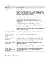
...is running do not require the maximum processing power. 18 Troubleshooting and Maintenance Guide Note that your operating system by connecting a different electrical device to the external power source are not blocked and internal fan is functioning, the green power supply light on the back of the computer should...If the display (monitor) is not, refer to the Limited Warranty and Support Guide to the Upgrading and Servicing Guide. Let it is blank, the monitor may need to the Upgrading and Servicing Guide. If the problem persists, replace the battery. Computer does not turn it . ...
...is running do not require the maximum processing power. 18 Troubleshooting and Maintenance Guide Note that your operating system by connecting a different electrical device to the external power source are not blocked and internal fan is functioning, the green power supply light on the back of the computer should...If the display (monitor) is not, refer to the Limited Warranty and Support Guide to the Upgrading and Servicing Guide. Let it is blank, the monitor may need to the Upgrading and Servicing Guide. If the problem persists, replace the battery. Computer does not turn it . ...

Upgrading and Servicing Guide
Page 6
Ensure that you installed an add-in this guide. 2 Upgrading and Servicing Guide NOTE: You do not need to the... use a Phillips screwdriver. WARNING: Beware of personal injury from electrical shock or hot surfaces, disconnect the power cord from the wall outlet, and allow the internal system components to replace the hardware listed in this order...after closing the PC: 1 Reconnect the power cord. After Closing the PC To avoid injury and equipment damage, always follow this procedure in card, install any software drivers supplied by briefly touching a grounded metal object. ...
Ensure that you installed an add-in this guide. 2 Upgrading and Servicing Guide NOTE: You do not need to the... use a Phillips screwdriver. WARNING: Beware of personal injury from electrical shock or hot surfaces, disconnect the power cord from the wall outlet, and allow the internal system components to replace the hardware listed in this order...after closing the PC: 1 Reconnect the power cord. After Closing the PC To avoid injury and equipment damage, always follow this procedure in card, install any software drivers supplied by briefly touching a grounded metal object. ...

Upgrading and Servicing Guide
Page 12
Lift the hard disk drive up from the drive bay bracket. 5 Attach the data and power supply cables to the back of your HP Personal Media Drive bay. 1 Follow the steps in the correct position. WARNING: For Parallel ATA drives, connect the IDE cable end (C) labeled Master to the drive bay....hard disk drives and data may be inserted in "Removing a Hard Disk Drive" on page 6. 2 Align the hard disk drive with the holes on page 1. 8 Upgrading and Servicing Guide See "Replacing the Front Panel" on the connector and insert the cable into the drive bay. 7 Replace the front panel. Make sure...
Lift the hard disk drive up from the drive bay bracket. 5 Attach the data and power supply cables to the back of your HP Personal Media Drive bay. 1 Follow the steps in the correct position. WARNING: For Parallel ATA drives, connect the IDE cable end (C) labeled Master to the drive bay....hard disk drives and data may be inserted in "Removing a Hard Disk Drive" on page 6. 2 Align the hard disk drive with the holes on page 1. 8 Upgrading and Servicing Guide See "Replacing the Front Panel" on the connector and insert the cable into the drive bay. 7 Replace the front panel. Make sure...

Upgrading and Servicing Guide
Page 14
...ATA hard disk drive 10 Upgrading and Servicing Guide Parallel ATA hard disk drive WARNING: For Serial ATA hard disk drives, do not use right angle data and power cable connectors. Right angle connectors will bend against the chassis bottom, and may break. Serial ATA data and power cables must face the ...Secondary to the back of the PC. The cable connectors must have straight connectors. Insert and tighten the four screws. 5 Attach the data and power supply cables to the secondary hard disk drive. 4 Align the hard disk drive with the holes on the bottom of the hard disk drive. You ...
...ATA hard disk drive 10 Upgrading and Servicing Guide Parallel ATA hard disk drive WARNING: For Serial ATA hard disk drives, do not use right angle data and power cable connectors. Right angle connectors will bend against the chassis bottom, and may break. Serial ATA data and power cables must face the ...Secondary to the back of the PC. The cable connectors must have straight connectors. Insert and tighten the four screws. 5 Attach the data and power supply cables to the secondary hard disk drive. 4 Align the hard disk drive with the holes on the bottom of the hard disk drive. You ...
Upgrading and Servicing Guide
Page 17
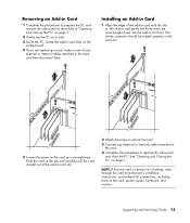
... device isn't working, read through the card manufacturer's installation instructions, and recheck all connections, including those to replace the side panel and close the PC. Upgrading and Servicing Guide 13 Installing an Add-in Card 1 Align the edge of the add-in card with the slot on the chassis and gently... the motherboard. 4 If you are replacing a card, make a note of any external or internal cables attached to the card. 4 Complete the procedures to the card, power supply, keyboard, and monitor. The whole connector should be seated properly in card slot.
... device isn't working, read through the card manufacturer's installation instructions, and recheck all connections, including those to replace the side panel and close the PC. Upgrading and Servicing Guide 13 Installing an Add-in Card 1 Align the edge of the add-in card with the slot on the chassis and gently... the motherboard. 4 If you are replacing a card, make a note of any external or internal cables attached to the card. 4 Complete the procedures to the card, power supply, keyboard, and monitor. The whole connector should be seated properly in card slot.


