HP LaserJet Printer Family - Print Media Specification Guide
Page 29
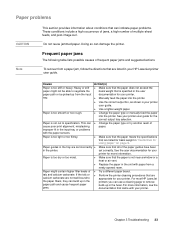
...printer. Paper is too light or too flimsy. For more information. Chapter 3 Troubleshooting 23 q Replace the paper in the paper path and cause frequent paper jams. q Try a different paper ...paper guides have been in the printer. Paper is too smooth or too rough. For most HP LaserJet printers you can use a cleaning page to the paper fibers, they can damage the printer.... Doing so can build up in "Guidelines for basis weight in the fuser. To recover from a paper jam, follow the directions that are set correctly. Heavy or stiff ...
...printer. Paper is too light or too flimsy. For more information. Chapter 3 Troubleshooting 23 q Replace the paper in the paper path and cause frequent paper jams. q Try a different paper ...paper guides have been in the printer. Paper is too smooth or too rough. For most HP LaserJet printers you can use a cleaning page to the paper fibers, they can damage the printer.... Doing so can build up in "Guidelines for basis weight in the fuser. To recover from a paper jam, follow the directions that are set correctly. Heavy or stiff ...
HP PCL/PJL reference - Printer Job Language Technical Reference Addendum
Page 122
... ORDER SUPPLIES PAGES LEFT REPLACE BLACK TONER REPLACE CYAN TONER REPLACE MAGENTA TONER REPLACE YELLOW TONER REPLACE IMAGE DRUM REPLACE BLACK DRUM REPLACE CYAN DRUM REPLACE MAGENTA DRUM REPLACE YELLOW DRUM REPLACE BLACK CARTRIDGE REPLACE CYAN CARTRIDGE REPLACE MAGENTA CARTRIDGE REPLACE YELLOW CARTRIDGE REPLACE TRANSPORT KIT REPLACE CLEANING KIT REPLACE TRANSFER KIT REPLACE FUSER KIT PERFORM PRINTER MAINTENANCE REPLACE SUPPLIES NON-HP SUPPLIES IN USE Genuine HP Supplies Tells the CP...
... ORDER SUPPLIES PAGES LEFT REPLACE BLACK TONER REPLACE CYAN TONER REPLACE MAGENTA TONER REPLACE YELLOW TONER REPLACE IMAGE DRUM REPLACE BLACK DRUM REPLACE CYAN DRUM REPLACE MAGENTA DRUM REPLACE YELLOW DRUM REPLACE BLACK CARTRIDGE REPLACE CYAN CARTRIDGE REPLACE MAGENTA CARTRIDGE REPLACE YELLOW CARTRIDGE REPLACE TRANSPORT KIT REPLACE CLEANING KIT REPLACE TRANSFER KIT REPLACE FUSER KIT PERFORM PRINTER MAINTENANCE REPLACE SUPPLIES NON-HP SUPPLIES IN USE Genuine HP Supplies Tells the CP...
HP PCL/PJL reference - Printer Job Language Technical Reference Addendum
Page 140
... PERFORM PRINTER MAINTENANCE ORDER SUPPLIES PAGES LEFT REPLACE BLACK TONER REPLACE CYAN TONER REPLACE MAGENTA TONER REPLACE YELLOW TONER REPLACE IMAGE DRUM REPLACE BLACK DRUM REPLACE CYAN DRUM REPLACE MAGENTA DRUM REPLACE YELLOW DRUM REPLACE BLACK CARTRIDGE REPLACE CYAN CARTRIDGE REPLACE MAGENTA CARTRIDGE REPLACE YELLOW CARTRIDGE REPLACE TRANSPORT KIT REPLACE CLEANING KIT REPLACE TRANFER KIT REPLACE FUSER KIT PERFORM PRINTER MAINTENANCE REPLACE SUPPLIES INSTALL BLACK TONER INSTALL CYAN TONER...
... PERFORM PRINTER MAINTENANCE ORDER SUPPLIES PAGES LEFT REPLACE BLACK TONER REPLACE CYAN TONER REPLACE MAGENTA TONER REPLACE YELLOW TONER REPLACE IMAGE DRUM REPLACE BLACK DRUM REPLACE CYAN DRUM REPLACE MAGENTA DRUM REPLACE YELLOW DRUM REPLACE BLACK CARTRIDGE REPLACE CYAN CARTRIDGE REPLACE MAGENTA CARTRIDGE REPLACE YELLOW CARTRIDGE REPLACE TRANSPORT KIT REPLACE CLEANING KIT REPLACE TRANFER KIT REPLACE FUSER KIT PERFORM PRINTER MAINTENANCE REPLACE SUPPLIES INSTALL BLACK TONER INSTALL CYAN TONER...
HP PCL/PJL reference - Printer Job Language Technical Reference Addendum
Page 142
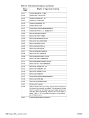
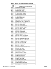
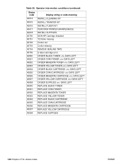
...40905 40906 40907 40908 Display string or code meaning INSTALL CLEANING KIT INSTALL TRANFER KIT INSTALL FUSER KIT PERFORM PRINTER MAINTENANCE INSTALL SUPPLIES NON-HP Cartridge Installed T2 Roller missing Croller out Croller missing REMOVE SEALING TAPE E-label cartridge error...MAGENTA CARTRIDGE DAYS LEFT ORDER YELLOW CARTRIDGE DAYS LEFT ORDER SUPPLIES DAYS LEFT REPLACE BLACK TONER REPLACE CYAN TONER REPLACE MAGENTA TONER REPLACE YELLOW TONER REPLACE BLACK CARTRIDGE REPLACE CYAN CARTRIDGE REPLACE MAGENTA CARTRIDGE REPLACE YELLOW CARTRIDGE REPLACE SUPPLIES 140 Chapter 4 PJL status codes ENWW
...40905 40906 40907 40908 Display string or code meaning INSTALL CLEANING KIT INSTALL TRANFER KIT INSTALL FUSER KIT PERFORM PRINTER MAINTENANCE INSTALL SUPPLIES NON-HP Cartridge Installed T2 Roller missing Croller out Croller missing REMOVE SEALING TAPE E-label cartridge error...MAGENTA CARTRIDGE DAYS LEFT ORDER YELLOW CARTRIDGE DAYS LEFT ORDER SUPPLIES DAYS LEFT REPLACE BLACK TONER REPLACE CYAN TONER REPLACE MAGENTA TONER REPLACE YELLOW TONER REPLACE BLACK CARTRIDGE REPLACE CYAN CARTRIDGE REPLACE MAGENTA CARTRIDGE REPLACE YELLOW CARTRIDGE REPLACE SUPPLIES 140 Chapter 4 PJL status codes ENWW
Service Manual
Page 6
... 6-10 Delivery Assembly Removal (2 of 2 6-14 Figure 6-11 Fuser Pressure Plate Removal 6-15 Figure 6-12 Fuser Pressure Plate Replacement 6-16 Figure 6-13 Heating Element Removal (1 of 3 6-17 ...Replacement 6-23 Figure 6-20 Laser/Scanner Assembly Removal 6-24 Figure 6-21 Solenoid Removal (1 of 2 6-25 Figure 6-22 Solenoid Removal (2 of 2 6-26 Figure 6-23 Pickup Roller Assembly Removal (1 of the Printer 1-9 Figure 2-1 Printer Space Requirements 2-4 Figure 2-2 Toner Cartridge Distribution 2-6 Figure 3-1 Self-test Page for HP LaserJet 5L 3-7 Figure 3-2 Self-test Page for HP LaserJet 6L...
... 6-10 Delivery Assembly Removal (2 of 2 6-14 Figure 6-11 Fuser Pressure Plate Removal 6-15 Figure 6-12 Fuser Pressure Plate Replacement 6-16 Figure 6-13 Heating Element Removal (1 of 3 6-17 ...Replacement 6-23 Figure 6-20 Laser/Scanner Assembly Removal 6-24 Figure 6-21 Solenoid Removal (1 of 2 6-25 Figure 6-22 Solenoid Removal (2 of 2 6-26 Figure 6-23 Pickup Roller Assembly Removal (1 of the Printer 1-9 Figure 2-1 Printer Space Requirements 2-4 Figure 2-2 Toner Cartridge Distribution 2-6 Figure 3-1 Self-test Page for HP LaserJet 5L 3-7 Figure 3-2 Self-test Page for HP LaserJet 6L...
Service Manual
Page 74
... Replacement Contents Removal and Replacement Strategy 6-3 Required Tools 6-4 Installing Memory Cards (DRAM 6-5 Covers and Doors 6-6 Back Cover 6-6 EP Door Assembly 6-8 Memory Door 6-9 Main Cover and Paper Input Assembly 6-10 Internal Assemblies 6-11 Control Panel 6-11 Exit Roller Assembly 6-12 Delivery Assembly 6-13 Fuser... Pressure Plate 6-15 Heating Element 6-17 Pressure Roller 6-20 Face-Up/Face-Down Lever 6-21 Fuser Exit Roller Assembly 6-22 Paper Exit Sensor Flag 6-23 Top Assemblies 6-24...
... Replacement Contents Removal and Replacement Strategy 6-3 Required Tools 6-4 Installing Memory Cards (DRAM 6-5 Covers and Doors 6-6 Back Cover 6-6 EP Door Assembly 6-8 Memory Door 6-9 Main Cover and Paper Input Assembly 6-10 Internal Assemblies 6-11 Control Panel 6-11 Exit Roller Assembly 6-12 Delivery Assembly 6-13 Fuser... Pressure Plate 6-15 Heating Element 6-17 Pressure Roller 6-20 Face-Up/Face-Down Lever 6-21 Fuser Exit Roller Assembly 6-22 Paper Exit Sensor Flag 6-23 Top Assemblies 6-24...
Service Manual
Page 86
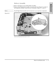
Removal and 6 Replacement Note Figure 6-9 Delivery Assembly 1 Remove the Printer Covers and Exit Roller Assembly. 2 Remove the EP Right-Hand assembly by pressing the tab in (Figure 6-9, callout 1) and sliding the assembly toward the front of 2) Removal and Replacement 6 - 13 The EP Right-Hand assembly must be removed to access any fuser components. Delivery Assembly Removal (1 of the printer (Figure 6-9, callout 2).
Removal and 6 Replacement Note Figure 6-9 Delivery Assembly 1 Remove the Printer Covers and Exit Roller Assembly. 2 Remove the EP Right-Hand assembly by pressing the tab in (Figure 6-9, callout 1) and sliding the assembly toward the front of 2) Removal and Replacement 6 - 13 The EP Right-Hand assembly must be removed to access any fuser components. Delivery Assembly Removal (1 of the printer (Figure 6-9, callout 2).

Service Manual
Page 87
Once the screws have been removed, rotate the rear of the Delivery Assembly up and forward and lift it out of the Delivery Assembly must fit under the sheet metal fuser plate below to remove the (2) screws (Figure 6-10, callout 1). Figure 6-10 3 Use the magnetic screwdriver to correctly reseat the Delivery Assembly. 6 - 14 Removal and Replacement Note Delivery Assembly Removal (2 of 2) Upon reinstallation, the tabs on the front end of the printer.
Once the screws have been removed, rotate the rear of the Delivery Assembly up and forward and lift it out of the Delivery Assembly must fit under the sheet metal fuser plate below to remove the (2) screws (Figure 6-10, callout 1). Figure 6-10 3 Use the magnetic screwdriver to correctly reseat the Delivery Assembly. 6 - 14 Removal and Replacement Note Delivery Assembly Removal (2 of 2) Upon reinstallation, the tabs on the front end of the printer.

Service Manual
Page 88
Fuser Pressure Plate Removal Removal and Replacement 6 - 15 Removal and 6 Replacement Figure 6-11 Fuser Pressure Plate 1 Remove Printer Covers and Delivery Assembly (Figures 6-9 and 6-10). 2 Remove the (2) screws (Figure 6-11, callout 1). 3 Press the Fuser Plate retainer clips out to release the Pressure Plate (Figure 6-11, callout 2). 4 Rotate the plate around and toward the back and lift up to remove it (Figure 6-11, callout 3).
Fuser Pressure Plate Removal Removal and Replacement 6 - 15 Removal and 6 Replacement Figure 6-11 Fuser Pressure Plate 1 Remove Printer Covers and Delivery Assembly (Figures 6-9 and 6-10). 2 Remove the (2) screws (Figure 6-11, callout 1). 3 Press the Fuser Plate retainer clips out to release the Pressure Plate (Figure 6-11, callout 2). 4 Rotate the plate around and toward the back and lift up to remove it (Figure 6-11, callout 3).

Service Manual
Page 89
Place the rear slits in each corner. Lower the plate over the rear brackets that the spring is kept in place by four locking mechanisms in the plate over the retaining clips, pressing on both sides of the Fuser Pressure Plate (Figure 6-12, callout, 2). Fuser Pressure Plate Replacement 6 - 16 Removal and Replacement It is important that hold the Fusing Assembly (Figure 6-12, callout 1). Figure 6-12 To reinstall: The Fuser Pressure Plate is placed over the positioning pin (callout 3) because inadequate pressure will cause fusing problems. Replace the screws.
Place the rear slits in each corner. Lower the plate over the rear brackets that the spring is kept in place by four locking mechanisms in the plate over the retaining clips, pressing on both sides of the Fuser Pressure Plate (Figure 6-12, callout, 2). Fuser Pressure Plate Replacement 6 - 16 Removal and Replacement It is important that hold the Fusing Assembly (Figure 6-12, callout 1). Figure 6-12 To reinstall: The Fuser Pressure Plate is placed over the positioning pin (callout 3) because inadequate pressure will cause fusing problems. Replace the screws.

Service Manual
Page 90
Removal and 6 Replacement Figure 6-13 Heating Element 1 Remove Printer Covers, Delivery Assembly (Figures 6-9 and 6-10), and Fuser Pressure Plate (Figure 6-11). 2 Remove the wire cover (on the tab and pulling outward (Figure 6-13, callout 1). Heating Element Removal (1 of the printer) for the Heating Element wires by pressing in on the right side of 3) Removal and Replacement 6 - 17
Removal and 6 Replacement Figure 6-13 Heating Element 1 Remove Printer Covers, Delivery Assembly (Figures 6-9 and 6-10), and Fuser Pressure Plate (Figure 6-11). 2 Remove the wire cover (on the tab and pulling outward (Figure 6-13, callout 1). Heating Element Removal (1 of the printer) for the Heating Element wires by pressing in on the right side of 3) Removal and Replacement 6 - 17
Service Manual
Page 93
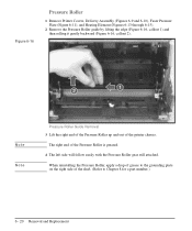
...right end of the Pressure Roller up and out of the shaft. (Refer to Chapter 8 for a part number.) 6 - 20 Removal and Replacement When reinstalling the Pressure Roller, apply a drop of grease to the grounding plate on the right side of the printer chassis. The right end... side will follow easily with the Pressure Roller gear still attached. Figure 6-16 Pressure Roller 1 Remove Printer Covers, Delivery Assembly (Figures 6-9 and 6-10), Fuser Pressure Plate (Figure 6-11), and Heating Element (Figures 6-13 through 6-15). 2 Remove the Pressure Roller guide by lifting the edge (Figure 6-16, ...
...right end of the Pressure Roller up and out of the shaft. (Refer to Chapter 8 for a part number.) 6 - 20 Removal and Replacement When reinstalling the Pressure Roller, apply a drop of grease to the grounding plate on the right side of the printer chassis. The right end... side will follow easily with the Pressure Roller gear still attached. Figure 6-16 Pressure Roller 1 Remove Printer Covers, Delivery Assembly (Figures 6-9 and 6-10), Fuser Pressure Plate (Figure 6-11), and Heating Element (Figures 6-13 through 6-15). 2 Remove the Pressure Roller guide by lifting the edge (Figure 6-16, ...

Service Manual
Page 94
...the spring's release mechanism. Figure 6-17 shows the lever from an HP LaserJet 5L. The machined ridges on the Separation Guide Assembly. Removal and 6 Replacement Note Figure 6-17 Face-Up/Face-Down Lever 1 Remove Printer Covers, Delivery Assembly (Figures 6-9 and 6-10), Fuser Pressure Plate (Figure 6-11), and Heating Element (Figures 6-13 through ... of the Exit Rollers, and you . 4 Release the spring so it straight out the front of the lever was changed for the HP LaserJet 6L (a stiffening rod was also added), these procedures for Face-Up/Face-Down Lever removal remain unchanged.
...the spring's release mechanism. Figure 6-17 shows the lever from an HP LaserJet 5L. The machined ridges on the Separation Guide Assembly. Removal and 6 Replacement Note Figure 6-17 Face-Up/Face-Down Lever 1 Remove Printer Covers, Delivery Assembly (Figures 6-9 and 6-10), Fuser Pressure Plate (Figure 6-11), and Heating Element (Figures 6-13 through ... of the Exit Rollers, and you . 4 Release the spring so it straight out the front of the lever was changed for the HP LaserJet 6L (a stiffening rod was also added), these procedures for Face-Up/Face-Down Lever removal remain unchanged.

Service Manual
Page 95
...Replacement While the shape of the roller shaft by pressing down on the catching mechanism with the small flathead screwdriver and pulling the gear away. 3 Remove the Exit Roller Assembly by pressing the small, white tab upward (Figure 6-18, callout 1) and rotating it around (Figure 6-18, callout 2). Note Figure 6-18 Fuser... gear from an HP LaserJet 5L. 4 Slide the Exit Roller Assembly forward and out to the right of the printer. Figure 6-18 shows the white tab from the left end of the white tab was changed for the HP LaserJet 6L, these procedures for Fuser Exit Roller Assembly removal...
...Replacement While the shape of the roller shaft by pressing down on the catching mechanism with the small flathead screwdriver and pulling the gear away. 3 Remove the Exit Roller Assembly by pressing the small, white tab upward (Figure 6-18, callout 1) and rotating it around (Figure 6-18, callout 2). Note Figure 6-18 Fuser... gear from an HP LaserJet 5L. 4 Slide the Exit Roller Assembly forward and out to the right of the printer. Figure 6-18 shows the white tab from the left end of the white tab was changed for the HP LaserJet 6L, these procedures for Fuser Exit Roller Assembly removal...

Service Manual
Page 96
...the flag (Figure 6-19). The spring must be reinstalled to Step 2, examine the Paper Exit Sensor flag. Paper Exit Sensor Flag Replacement Removal and Replacement 6 - 23 To reinstall It is important that you reinstall the flag correctly, because installing it may require "respringing" by pressing ...down on top of the flag in place. Removal and 6 Replacement Caution Note Figure 6-19 Paper Exit Sensor Flag 1 Remove the Printer Covers, Delivery Assembly (Figures 6-9 and 6-10), and Fuser Pressure Plate (Figure 6-11).
...the flag (Figure 6-19). The spring must be reinstalled to Step 2, examine the Paper Exit Sensor flag. Paper Exit Sensor Flag Replacement Removal and Replacement 6 - 23 To reinstall It is important that you reinstall the flag correctly, because installing it may require "respringing" by pressing ...down on top of the flag in place. Removal and 6 Replacement Caution Note Figure 6-19 Paper Exit Sensor Flag 1 Remove the Printer Covers, Delivery Assembly (Figures 6-9 and 6-10), and Fuser Pressure Plate (Figure 6-11).

Service Manual
Page 131
... to identify what type of the cable. (This procedure will turn on . If the message clears, replace the memory card. 3. Note: Chronic fuser failures or fuser overheating or both the printer chassis and J206 of an uninterruptible power supply or battery backup being used with... the printer. Normal resistance is not measured replace the heating element. 5. Measure the resistance between pins one and two...
... to identify what type of the cable. (This procedure will turn on . If the message clears, replace the memory card. 3. Note: Chronic fuser failures or fuser overheating or both the printer chassis and J206 of an uninterruptible power supply or battery backup being used with... the printer. Normal resistance is not measured replace the heating element. 5. Measure the resistance between pins one and two...

Service Manual
Page 202
... 6-25 strategy 6-3 subpads 6-38 top assemblies 6-24 transfer roller 6-34 repair philosophy 1-10 repetitive defects 7-15 repetitive image defect ruler 7-28 replaceable cables 8-6 required tools 6-4 requirements environmental 2-5 site 2-1 to 2-6 space 2-4 resetting the printer 3-11 Resolution Enhancement technology 1-3, 5-9 described 5-9 resolution... service approach 1-10 service errors 7-7 service or error messages beam error 7-11 engine 7-11 firmware 7-12 formatter 7-12 fuser 7-10 ROM or RAM 7-10 scanner 7-12 site requirements 2-1 to 2-6 SME, Support Materials Europe 1-11 solving print quality...
... 6-25 strategy 6-3 subpads 6-38 top assemblies 6-24 transfer roller 6-34 repair philosophy 1-10 repetitive defects 7-15 repetitive image defect ruler 7-28 replaceable cables 8-6 required tools 6-4 requirements environmental 2-5 site 2-1 to 2-6 space 2-4 resetting the printer 3-11 Resolution Enhancement technology 1-3, 5-9 described 5-9 resolution... service approach 1-10 service errors 7-7 service or error messages beam error 7-11 engine 7-11 firmware 7-12 formatter 7-12 fuser 7-10 ROM or RAM 7-10 scanner 7-12 site requirements 2-1 to 2-6 SME, Support Materials Europe 1-11 solving print quality...


