HP PCL/PJL reference - Printer Job Language Technical Reference Manual
Page 273
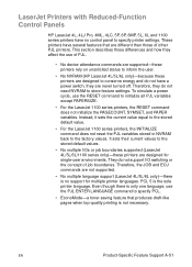
.../5L/6L only)-because these printers are not supported. • No multiple language support (LaserJet 4L/5L/6L only)-there is the sole printer language. LaserJet Printers with Reduced-Function Control Panels HP LaserJet 4L, 4LJ Pro, 4ML, 4LC, 5P, 6P, 6MP, 5L, 6L and 1100 series... their current values to initialize all PJL variables except PAPERSIZE. • For the LaserJet 1100 series printers, the RESET command does not initialize the PAGECOUNT, SYMSET, and PAPER variables. These printers have a power switch, they affect the use the RESET command to the stored default values. •...
.../5L/6L only)-because these printers are not supported. • No multiple language support (LaserJet 4L/5L/6L only)-there is the sole printer language. LaserJet Printers with Reduced-Function Control Panels HP LaserJet 4L, 4LJ Pro, 4ML, 4LC, 5P, 6P, 6MP, 5L, 6L and 1100 series... their current values to initialize all PJL variables except PAPERSIZE. • For the LaserJet 1100 series printers, the RESET command does not initialize the PAGECOUNT, SYMSET, and PAPER variables. These printers have a power switch, they affect the use the RESET command to the stored default values. •...

HP LaserJet 4100mfp -User Guide
Page 18
Introduction EN Parts Product parts (front view) 11 1 10 2 9 3 8 4 7 5 6 1 ADF 2 ADF cover (lifts for access to scanner glass) 3 Top cover (access to toner cartridge 9 Control panel 10 Output bin 11 Scanner lock (located on the left side of the MFP) 16 Chapter 1 - serial and part numbers are stacked below, if installed) 7 Tray 1 (holds 100 sheets) 8 Access to toner cartridge; Trays 3 and 4 are underneath cover) 4 Duplexer or Tray 2 dust cover (dust cover is removed if duplexer is installed) 5 Power switch 6 Tray 2 (holds 500 sheets;
Introduction EN Parts Product parts (front view) 11 1 10 2 9 3 8 4 7 5 6 1 ADF 2 ADF cover (lifts for access to scanner glass) 3 Top cover (access to toner cartridge 9 Control panel 10 Output bin 11 Scanner lock (located on the left side of the MFP) 16 Chapter 1 - serial and part numbers are stacked below, if installed) 7 Tray 1 (holds 100 sheets) 8 Access to toner cartridge; Trays 3 and 4 are underneath cover) 4 Duplexer or Tray 2 dust cover (dust cover is removed if duplexer is installed) 5 Power switch 6 Tray 2 (holds 500 sheets;
HP LaserJet 4100mfp -User Guide
Page 71
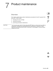
Overview 69 These include: q managing the toner cartridge q cleaning the product q performing preventative maintenance Turn the main power-switch off and unplug the MFP before you disconnect any cables or accessories, and before you perform preventive maintenance or cleaning. If these activities are performed while the MFP is powered on and plugged in, serious product damage may result. 7 Product maintenance CAUTION Overview This chapter explains basic product maintenance procedures for the HP LaserJet 4100 mfp series.
Overview 69 These include: q managing the toner cartridge q cleaning the product q performing preventative maintenance Turn the main power-switch off and unplug the MFP before you disconnect any cables or accessories, and before you perform preventive maintenance or cleaning. If these activities are performed while the MFP is powered on and plugged in, serious product damage may result. 7 Product maintenance CAUTION Overview This chapter explains basic product maintenance procedures for the HP LaserJet 4100 mfp series.

HP LaserJet 4100 Series - User Guide
Page 21
Printer parts and locations Printer parts (front view, HP LaserJet 4100/4100N printer) Top output bin Top cover (toner cartridge underneath) Control panel Additional memory can be installed here Tray 1 (100-sheet) Power switch Paper level 1 indicator 2 Tray 2 (500-sheet) Tray numbers EN Printer parts and locations 19
Printer parts and locations Printer parts (front view, HP LaserJet 4100/4100N printer) Top output bin Top cover (toner cartridge underneath) Control panel Additional memory can be installed here Tray 1 (100-sheet) Power switch Paper level 1 indicator 2 Tray 2 (500-sheet) Tray numbers EN Printer parts and locations 19

HP LaserJet 4100 series printers - Getting Started Guide
Page 15
Step 4: Locate printer parts Front view 8 1 7 6 1 2 5 3 4 2 1 Control panel 2 Tray number 3 Power switch 4 Tray 2 (500-sheet) 5 Paper level indicator 6 Tray 1, closed (100-sheet) 7 Top cover (toner cartridge underneath) 8 Top output bin 1-14 Getting Started EN
Step 4: Locate printer parts Front view 8 1 7 6 1 2 5 3 4 2 1 Control panel 2 Tray number 3 Power switch 4 Tray 2 (500-sheet) 5 Paper level indicator 6 Tray 1, closed (100-sheet) 7 Top cover (toner cartridge underneath) 8 Top output bin 1-14 Getting Started EN
HP LaserJet 4100 series printers - Getting Started Guide
Page 22
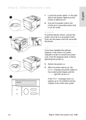
WARNING! To prevent electric shock, connect the power cord only to the printer and a grounded power strip or an AC outlet. English Step 8: Attach the power cord 1 2 3 4 READY 1 Locate the power switch on . Only use the power cord that came with the printer. If the READY message does not appear, go to ...in order to be visible on the control panel display and the READY light will need to connect the power cord. Push the duplexer back in before switching the printer on. 3 Switch the printer on. 4 After the printer warms up, the READY message should be pulled outward in the...
WARNING! To prevent electric shock, connect the power cord only to the printer and a grounded power strip or an AC outlet. English Step 8: Attach the power cord 1 2 3 4 READY 1 Locate the power switch on . Only use the power cord that came with the printer. If the READY message does not appear, go to ...in order to be visible on the control panel display and the READY light will need to connect the power cord. Push the duplexer back in before switching the printer on. 3 Switch the printer on. 4 After the printer warms up, the READY message should be pulled outward in the...

Service Manual
Page 38
... below . Cleaning the product General guidelines Perform the following cleaning procedures when you perform preventative maintenance or cleaning. WARNING! Turn the main power-switch off and unplug the MFP power cord before you disconnect any cables or accessories, and before you change the print cartridge or when printquality problems occur. Skin oils on...
... below . Cleaning the product General guidelines Perform the following cleaning procedures when you perform preventative maintenance or cleaning. WARNING! Turn the main power-switch off and unplug the MFP power cord before you disconnect any cables or accessories, and before you change the print cartridge or when printquality problems occur. Skin oils on...

Service Manual
Page 116
...unit is properly plugged into its receptacle on page 128. Perform a print-engine test (see the HP 4100 series printer service manual for about 3 seconds. 1. Verify that the power switch is turned on page 80. See "Control-panel door" on the control panel door. Basic ...troubleshooting # Verification steps Possible problems Solutions 1 Is Power On successful? When power is on page 120. Verify the control panel ...
...unit is properly plugged into its receptacle on page 128. Perform a print-engine test (see the HP 4100 series printer service manual for about 3 seconds. 1. Verify that the power switch is turned on page 80. See "Control-panel door" on the control panel door. Basic ...troubleshooting # Verification steps Possible problems Solutions 1 Is Power On successful? When power is on page 120. Verify the control panel ...

Service Manual
Page 118
...HP LaserJet 4100 series printer service manual for frayed, pinched, or damaged wires. q q q q Verify that the control-panel wire harness is supplied. Hint The control panel gets its power from the print unit to the scan unit is blank or displays garbled text. q Replace the power supply. No ac power...panel cable connector location J1210 on page 101. Defective power-supply unit. See "Scan-unit power supply" on the scanner controller PCB is functioning (power on page 21. No dc power. Note Leave the MFP off the power switch. If no problem exists on page 63. 116 ...
...HP LaserJet 4100 series printer service manual for frayed, pinched, or damaged wires. q q q q Verify that the control-panel wire harness is supplied. Hint The control panel gets its power from the print unit to the scan unit is blank or displays garbled text. q Replace the power supply. No ac power...panel cable connector location J1210 on page 101. Defective power-supply unit. See "Scan-unit power supply" on the scanner controller PCB is functioning (power on page 21. No dc power. Note Leave the MFP off the power switch. If no problem exists on page 63. 116 ...

Service Manual
Page 430
... converted into +24 VA, which is constantly supplied from the power receptacle is converted into DC power. The +24 VDC is divided into +24 VDC, +5 VDC, and +3.3 VDC in the engine controller board when the power switch (SW1) is turned on the engine controller board and relay (RL102). It also functions as a door-open...
... converted into +24 VA, which is constantly supplied from the power receptacle is converted into DC power. The +24 VDC is divided into +24 VDC, +5 VDC, and +3.3 VDC in the engine controller board when the power switch (SW1) is turned on the engine controller board and relay (RL102). It also functions as a door-open...
Service Manual
Page 483
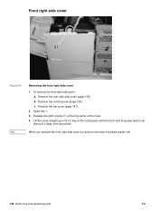
Hint Removing the front right side cover 1 To remove the front right side cover: a Remove the rear right side cover (page 138). When you reinstall the front right side cover, be sure to reconnect the power switch rod. 144 Removing and replacing parts EN c Remove the top cover (page 141). 2 Open tray 1. 3 Release the latch (callout 1) at the top center of the cover. 4 Lift the cover straight up until it is free of the locating pins at the bottom and the power switch rod, then pull it away from the printer. b Remove the control panel (page 139). Front right side cover 12 Figure 47.
Hint Removing the front right side cover 1 To remove the front right side cover: a Remove the rear right side cover (page 138). When you reinstall the front right side cover, be sure to reconnect the power switch rod. 144 Removing and replacing parts EN c Remove the top cover (page 141). 2 Open tray 1. 3 Release the latch (callout 1) at the top center of the cover. 4 Lift the cover straight up until it is free of the locating pins at the bottom and the power switch rod, then pull it away from the printer. b Remove the control panel (page 139). Front right side cover 12 Figure 47.

Service Manual
Page 512
... self-tapping M4 screws (three in front and one in the right rear) • From the left rear, three M3 screws (two recessed) 4 Disconnect the power switch rod. Note Engine controller board After you replace the engine controller board, readjust the top margin as described on the underside of the engine. Figure...
... self-tapping M4 screws (three in front and one in the right rear) • From the left rear, three M3 screws (two recessed) 4 Disconnect the power switch rod. Note Engine controller board After you replace the engine controller board, readjust the top margin as described on the underside of the engine. Figure...

Service Manual
Page 513
The black cable holder in the middle of the engine controller board can be folded aside with the cables intact. When you replace the board, reconnect and route all connectors from the fan side, tip the board up. Use masking tape and a pen to identify all cables, if necessary. 7 Unplug all cables before reconnecting the power switch rod. 174 Removing and replacing parts EN Figure 81. Hint Hint Removing the engine controller board 5 Disconnect the three connectors on the fan side. 6 Lifting from the engine controller board.
The black cable holder in the middle of the engine controller board can be folded aside with the cables intact. When you replace the board, reconnect and route all connectors from the fan side, tip the board up. Use masking tape and a pen to identify all cables, if necessary. 7 Unplug all cables before reconnecting the power switch rod. 174 Removing and replacing parts EN Figure 81. Hint Hint Removing the engine controller board 5 Disconnect the three connectors on the fan side. 6 Lifting from the engine controller board.

Service Manual
Page 527
... turning the printer back on position. Replace the fuses if necessary. 188 Troubleshooting EN The power switch is not Measure the voltage at the outlet. Power on , and high (over 6 MΩ) when the switch is turned off . Remove the engine controller board. 2. Measure the resistance between the two... another AC circuit outlet. If the printer still does not turn on, the power switch might be low (under 1 KΩ) when the power is turned on defect or blank display Problem Action The power cord is firmly plugged into the wall outlet and the printer. If the front...
... turning the printer back on position. Replace the fuses if necessary. 188 Troubleshooting EN The power switch is not Measure the voltage at the outlet. Power on , and high (over 6 MΩ) when the switch is turned off . Remove the engine controller board. 2. Measure the resistance between the two... another AC circuit outlet. If the printer still does not turn on, the power switch might be low (under 1 KΩ) when the power is turned on defect or blank display Problem Action The power cord is firmly plugged into the wall outlet and the printer. If the front...

Service Manual
Page 593
Engine controller board layout Table 46. Engine controller board Figure 105. Engine controller board layout SW1 Power switch SW501 Test-print switch SW502 Adjusted at factory VR501 Top-of-page adjustment VR601 Adjusted at factory 254 Troubleshooting EN
Engine controller board layout Table 46. Engine controller board Figure 105. Engine controller board layout SW1 Power switch SW501 Test-print switch SW502 Adjusted at factory VR501 Top-of-page adjustment VR601 Adjusted at factory 254 Troubleshooting EN

Service Manual
Page 603
... thermistors PS101 Tray 2 paper-out sensor PS102 Prefeed sensor PS103 Top-of 2) Table 50. Location of sensors, switches, and thermistor (2 of -page sensor PS104 Top output-bin-full sensor PS105 Tray 1 paper-out sensor PS106 Paper width sensor PS107 Fuser paper delivery sensor 2 ... (envelope feeder) PS902 Envelope multiple-feed sensor (envelope feeder) PS903 Envelope width sensor (envelope feeder) PS1001 Optional 500-sheet paper feeder paper-out sensor SW1 Power switch (engine controller board) 264 Troubleshooting EN Figure 114.
... thermistors PS101 Tray 2 paper-out sensor PS102 Prefeed sensor PS103 Top-of 2) Table 50. Location of sensors, switches, and thermistor (2 of -page sensor PS104 Top output-bin-full sensor PS105 Tray 1 paper-out sensor PS106 Paper width sensor PS107 Fuser paper delivery sensor 2 ... (envelope feeder) PS902 Envelope multiple-feed sensor (envelope feeder) PS903 Envelope width sensor (envelope feeder) PS1001 Optional 500-sheet paper feeder paper-out sensor SW1 Power switch (engine controller board) 264 Troubleshooting EN Figure 114.

Service Manual
Page 616
6 7 8 2 1 2 3 5 4 Figure 120. Quantity 1 RG5-2664-020CN 1 2 RB1-8860-000CN 1 3 RB1-8849-000CN 1 4 RG5-2667-070CN 1 5 RG5-5098-000CN 1 6 RB2-4827-000CN 1 7 RG5-5097-000CN 1 8 RB1-8858-000CN 1 Description Cover assembly, right front Clip, right side panel Power switch button Tray 1 door assembly Cover assembly, left Cover, tray 2 Tray assembly, rear Panel, formatter cover EN Chapter 8 Parts and diagrams 277 External covers and panels Table 56. External covers and panels Item no . Part no .
6 7 8 2 1 2 3 5 4 Figure 120. Quantity 1 RG5-2664-020CN 1 2 RB1-8860-000CN 1 3 RB1-8849-000CN 1 4 RG5-2667-070CN 1 5 RG5-5098-000CN 1 6 RB2-4827-000CN 1 7 RG5-5097-000CN 1 8 RB1-8858-000CN 1 Description Cover assembly, right front Clip, right side panel Power switch button Tray 1 door assembly Cover assembly, left Cover, tray 2 Tray assembly, rear Panel, formatter cover EN Chapter 8 Parts and diagrams 277 External covers and panels Table 56. External covers and panels Item no . Part no .

Service Manual
Page 620
... 2 RB2-5013-000CN 2 Screw, M4 x 8.3 3 RB1-8704-030CN 1 Guide, bottom cable 4 RB1-8851-000CN 1 Power switch rod 5 RG5-5274-000CN 1 Front inner cover assembly 6 WC4-5139-000CN 1 Switch, top cover interlock access 7 RG5-5341-000CN 1 Cable, tray 1 sensor 8 RG5-5343-000CN 1 Cable, paper feed/tray... 1 pickup solenoid 9 RG5-5344-000CN 1 Cable, envelope feeder connect 10 RG5-5345-000CN 1 Cable, top cover switch 11 RG5-5346-000CN 1 Cable, main motor 12 RG5-5351-000CN 1 Cable, assembly, formatter 13 C8049-69001 C8049-69002 1 Fusing assembly (110...
... 2 RB2-5013-000CN 2 Screw, M4 x 8.3 3 RB1-8704-030CN 1 Guide, bottom cable 4 RB1-8851-000CN 1 Power switch rod 5 RG5-5274-000CN 1 Front inner cover assembly 6 WC4-5139-000CN 1 Switch, top cover interlock access 7 RG5-5341-000CN 1 Cable, tray 1 sensor 8 RG5-5343-000CN 1 Cable, paper feed/tray... 1 pickup solenoid 9 RG5-5344-000CN 1 Cable, envelope feeder connect 10 RG5-5345-000CN 1 Cable, top cover switch 11 RG5-5346-000CN 1 Cable, main motor 12 RG5-5351-000CN 1 Cable, assembly, formatter 13 C8049-69001 C8049-69002 1 Fusing assembly (110...

Service Manual
Page 649
...-000CN Photo-sensor WG8-5362-000CN Pickup drive assembly Pickup roller RG5-5298-000CN RB1-8957-000CN Plate, continuity Plate, grounding Plate, registration ground Power switch activator Power switch button Printer drive assembly RB2-5002-000CN RB1-9397-000CN RB2-4969-000CN RB1-8851-000CN RB1-8849-000CN RG5-5087-000CN Registration RG5-5085...
...-000CN Photo-sensor WG8-5362-000CN Pickup drive assembly Pickup roller RG5-5298-000CN RB1-8957-000CN Plate, continuity Plate, grounding Plate, registration ground Power switch activator Power switch button Printer drive assembly RB2-5002-000CN RB1-9397-000CN RB2-4969-000CN RB1-8851-000CN RB1-8849-000CN RG5-5087-000CN Registration RG5-5085...

Service Manual
Page 653
..., feeder assembly Table 53 on page 272 Table 70 on page 299 HPJ1124 HP LaserJet paper Table 52 on page 271 HPM1120 HP multi-purpose paper Table 52 on page 271 J4167A J4169A J4135A Enhanced I/O Cards... Token Ring networks Fast Ethernet (10/100Base-TX single RJ-45 port) HP JetDirect Connectivity card (EIO) for USB, Serial, LocalTalk Table 52 on page 271 RB1-2190-..., rear tray latch Table 57 on page 279 RB1-8849-000CN Power switch button Table 56 on page 277 RB1-8851-000CN Power switch activator Table 58 on page 281 RB1-8858-000CN Panel, formatter ...
..., feeder assembly Table 53 on page 272 Table 70 on page 299 HPJ1124 HP LaserJet paper Table 52 on page 271 HPM1120 HP multi-purpose paper Table 52 on page 271 J4167A J4169A J4135A Enhanced I/O Cards... Token Ring networks Fast Ethernet (10/100Base-TX single RJ-45 port) HP JetDirect Connectivity card (EIO) for USB, Serial, LocalTalk Table 52 on page 271 RB1-2190-..., rear tray latch Table 57 on page 279 RB1-8849-000CN Power switch button Table 56 on page 277 RB1-8851-000CN Power switch activator Table 58 on page 281 RB1-8858-000CN Panel, formatter ...


