Service Guide
Page 4
... parts catalog Serial number location 3-1 Computer major components 3-2 Display assembly components 3-9 Plastics Kit 3-11 Mass storage devices 3-12 Miscellaneous parts 3-13 Sequential part number listing 3-14 4 Removal and replacement procedures Preliminary replacement requirements 4-1 Tools required 4-1 Service considerations 4-1 Grounding guidelines 4-2 Unknown user password 4-4 Component replacement procedures 4-5 Serial number 4-5 Computer feet 4-6 Battery 4-7 Optical drive 4-8 Hard drive 4-10 RTC battery 4-12 Memory module 4-13 WLAN module 4-15 Keyboard 4-17 Keyboard...
... parts catalog Serial number location 3-1 Computer major components 3-2 Display assembly components 3-9 Plastics Kit 3-11 Mass storage devices 3-12 Miscellaneous parts 3-13 Sequential part number listing 3-14 4 Removal and replacement procedures Preliminary replacement requirements 4-1 Tools required 4-1 Service considerations 4-1 Grounding guidelines 4-2 Unknown user password 4-4 Component replacement procedures 4-5 Serial number 4-5 Computer feet 4-6 Battery 4-7 Optical drive 4-8 Hard drive 4-10 RTC battery 4-12 Memory module 4-13 WLAN module 4-15 Keyboard 4-17 Keyboard...
Service Guide
Page 5
.../off button board and board bracket 4-32 Audio board 4-34 Bluetooth module 4-35 Speakers 4-36 USB board 4-37 System board 4-38 Fan/heat sink assembly 4-41 Processor 4-44 Power connector cable 4-46 5 Setup Utility Starting the Setup Utility 5-1 Changing the language of the Setup Utility 5-1 Navigating and selecting in the Setup Utility 5-2 Displaying system information 5-2 Restoring default settings in the Setup Utility 5-2 Exiting the Setup Utility 5-3 Setup Utility menus 5-3 Main menu 5-3 Security menu 5-3 System Configuration menu 5-4 Diagnostics menu 5-4 6 Specifications...
.../off button board and board bracket 4-32 Audio board 4-34 Bluetooth module 4-35 Speakers 4-36 USB board 4-37 System board 4-38 Fan/heat sink assembly 4-41 Processor 4-44 Power connector cable 4-46 5 Setup Utility Starting the Setup Utility 5-1 Changing the language of the Setup Utility 5-1 Navigating and selecting in the Setup Utility 5-2 Displaying system information 5-2 Restoring default settings in the Setup Utility 5-2 Exiting the Setup Utility 5-3 Setup Utility menus 5-3 Main menu 5-3 Security menu 5-3 System Configuration menu 5-4 Diagnostics menu 5-4 6 Specifications...
Service Guide
Page 11
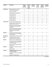
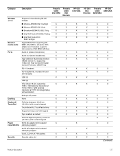
... and 512-MB memory) Webcam VGA camera, 640 x 480 resolution, X 22.5 frames per second, fixed angle with activity light Microphone Intregated single analog microphone X Audio High-definition audio supports X Microsoft premium requirements Modem 56K V.92 1.5-inch data/fax modem X Computer models not equipped with X a modem will have a cover on the RJ-11 jack opening Supports all 9.5-mm, 6.35-cm X (2.50-in) SATA hard drives Customer accessible X Single hard drive configurations: 120-GB...
... and 512-MB memory) Webcam VGA camera, 640 x 480 resolution, X 22.5 frames per second, fixed angle with activity light Microphone Intregated single analog microphone X Audio High-definition audio supports X Microsoft premium requirements Modem 56K V.92 1.5-inch data/fax modem X Computer models not equipped with X a modem will have a cover on the RJ-11 jack opening Supports all 9.5-mm, 6.35-cm X (2.50-in) SATA hard drives Customer accessible X Single hard drive configurations: 120-GB...
Service Guide
Page 12
... power X None X Full-size keyboard, 40.64-cm X (16.00-in) with numeric keypad TouchPad with 2 TouchPad buttons X Supports 2-way scroll with legend X Taps enabled as default X Full-size keyboard (silver), 40.64-cm (16.00-in) with numeric keypad 65-W AC adapter with localized X cable plug support 90-W AC adapter with localized cable plug support 6-cell, 2.20-Ah, 47-Wh battery X Security cable slot X Presario CQ60 Intel Discrete HP G60...
... power X None X Full-size keyboard, 40.64-cm X (16.00-in) with numeric keypad TouchPad with 2 TouchPad buttons X Supports 2-way scroll with legend X Taps enabled as default X Full-size keyboard (silver), 40.64-cm (16.00-in) with numeric keypad 65-W AC adapter with localized X cable plug support 90-W AC adapter with localized cable plug support 6-cell, 2.20-Ah, 47-Wh battery X Security cable slot X Presario CQ60 Intel Discrete HP G60...
Service Guide
Page 15
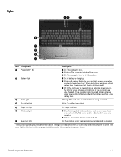
... charging. ■ Blinking: A battery that is open . The light on the front of the computer is visible whether the computer is the only available power source has reached a low battery level. Blinking: The hard drive or optical drive is being accessed. 4 TouchPad light White: TouchPad is enabled. 5 Caps lock light On: Caps lock is on. 6 Wireless light 7 Num lock light ■ Blue: An integrated wireless device, such as a wireless local area network (WLAN) device and/or a Bluetooth® device, is turned...
... charging. ■ Blinking: A battery that is open . The light on the front of the computer is visible whether the computer is the only available power source has reached a low battery level. Blinking: The hard drive or optical drive is being accessed. 4 TouchPad light White: TouchPad is enabled. 5 Caps lock light On: Caps lock is on. 6 Wireless light 7 Num lock light ■ Blue: An integrated wireless device, such as a wireless local area network (WLAN) device and/or a Bluetooth® device, is turned...
Service Guide
Page 19
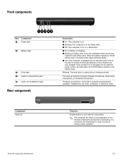
... Component 1 Power light 2 Battery light 3 Drive light 4 Audio-in (microphone) jack 5 Audio-out (headphone) jack Rear components Component Vents (2) Description ■ On: The computer is on and off during routine operation. Blinking: The hard drive or optical drive is not plugged into an external power source, the light is turned off until the battery reaches a low battery level. Connects an optional computer headset microphone, stereo array microphone, or monaural microphone. External component identification 2-6 Produces sound when connected to cool internal components...
... Component 1 Power light 2 Battery light 3 Drive light 4 Audio-in (microphone) jack 5 Audio-out (headphone) jack Rear components Component Vents (2) Description ■ On: The computer is on and off during routine operation. Blinking: The hard drive or optical drive is not plugged into an external power source, the light is turned off until the battery reaches a low battery level. Connects an optional computer headset microphone, stereo array microphone, or monaural microphone. External component identification 2-6 Produces sound when connected to cool internal components...
Service Guide
Page 20
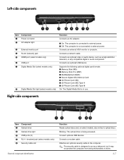
... a network cable. Connects an optional video or audio device, such as a deterrent, but it may not prevent the computer from being accessed. Left-side components Item Component 1 Power connector 2 AC adapter light 3 External monitor port 4 RJ-45 (network) jack 5 HDMI port (select models only) 6 USB port 7 Digital Media Slot (select models only) 8 Digital Media Slot light (select models only) Function Connects an AC adapter. ■ On: The computer is connected to external power. ■ Off: The computer is in use. Supports the following optional digital card formats: ■ Memory Stick...
... a network cable. Connects an optional video or audio device, such as a deterrent, but it may not prevent the computer from being accessed. Left-side components Item Component 1 Power connector 2 AC adapter light 3 External monitor port 4 RJ-45 (network) jack 5 HDMI port (select models only) 6 USB port 7 Digital Media Slot (select models only) 8 Digital Media Slot light (select models only) Function Connects an AC adapter. ■ On: The computer is connected to external power. ■ Off: The computer is in use. Supports the following optional digital card formats: ■ Memory Stick...
Service Guide
Page 21
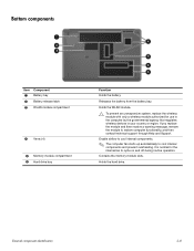
... regulates wireless devices in your country or region. Enable airflow to cool internal components. ✎ The computer fan starts up automatically to cycle on and off during routine operation. Holds the hard drive. Bottom components Item Component 1 Battery bay 2 Battery release latch 3 WLAN module compartment 4 Vents (4) 5 Memory module compartment 6 Hard drive bay Function Holds the battery. If you replace the module and then receive a warning message, remove the module to restore computer functionality, and...
... regulates wireless devices in your country or region. Enable airflow to cool internal components. ✎ The computer fan starts up automatically to cycle on and off during routine operation. Holds the hard drive. Bottom components Item Component 1 Battery bay 2 Battery release latch 3 WLAN module compartment 4 Vents (4) 5 Memory module compartment 6 Hard drive bay Function Holds the battery. If you replace the module and then receive a warning message, remove the module to restore computer functionality, and...
Service Guide
Page 22
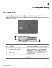
... period for the computer. Illustrated parts catalog 3-1 This number describes the duration of the computer. The part number helps a service technician to locate documents, drivers, and support for the computer. This is the number used to determine what components and parts are needed when troubleshooting system problems. The service tag provides the following information: When ordering parts or requesting information, provide the computer serial number and model number located on the service tag.
... period for the computer. Illustrated parts catalog 3-1 This number describes the duration of the computer. The part number helps a service technician to locate documents, drivers, and support for the computer. This is the number used to determine what components and parts are needed when troubleshooting system problems. The service tag provides the following information: When ordering parts or requesting information, provide the computer serial number and model number located on the service tag.

Service Guide
Page 30
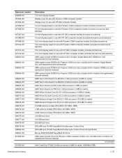
... Spare Part Number Display bezel For use only with 16-inch HP G60 display bezels (includes microphone) 497097-001 For use only with 16-inch HP G60 display bezels (includes microphone and webcam) 497098-001 For use only with 16-inch silver HP G60 display bezels (includes microphone) 502954-001 For use only with 16-inch silver HP G60 display bezels (includes microphone and webcam) 502955-001 For use only with 15.6-inch HP G60 display bezels (includes microphone) 497101...
... Spare Part Number Display bezel For use only with 16-inch HP G60 display bezels (includes microphone) 497097-001 For use only with 16-inch HP G60 display bezels (includes microphone and webcam) 497098-001 For use only with 16-inch silver HP G60 display bezels (includes microphone) 502954-001 For use only with 16-inch silver HP G60 display bezels (includes microphone and webcam) 502955-001 For use only with 15.6-inch HP G60 display bezels (includes microphone) 497101...
Service Guide
Page 39
... memory module (PC2-5300, 667-MHz, DDR) 120-GB hard drive 160-GB hard drive 250-GB hard drive DVD±RW and CD-RW SuperMulti Double-Layer Combo Drive DVD±RW and CD-RW SuperMulti Double-Layer Combo Drive with HP G60 computer models (includes microphone and webcam) UMA system board, NVIDIA (includes built-in modem, Digital Media Slot, and replacement thermal material) UMA system board, NVIDIA (for Presario CQ60 use...
... memory module (PC2-5300, 667-MHz, DDR) 120-GB hard drive 160-GB hard drive 250-GB hard drive DVD±RW and CD-RW SuperMulti Double-Layer Combo Drive DVD±RW and CD-RW SuperMulti Double-Layer Combo Drive with HP G60 computer models (includes microphone and webcam) UMA system board, NVIDIA (includes built-in modem, Digital Media Slot, and replacement thermal material) UMA system board, NVIDIA (for Presario CQ60 use...
Service Guide
Page 46
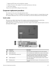
... replacement procedures This chapter provides removal and replacement procedures. This number provides specific information about the product's hardware components. The part number helps a service technician to locate documents, drivers, and support for the computer. 4-5 This number describes the duration of each product. Do not reinsert any batteries at this time. 9. Turn on the bottom of the computer. All passwords and all CMOS settings have been cleared. This is the number used...
... replacement procedures This chapter provides removal and replacement procedures. This number provides specific information about the product's hardware components. The part number helps a service technician to locate documents, drivers, and support for the computer. 4-5 This number describes the duration of each product. Do not reinsert any batteries at this time. 9. Turn on the bottom of the computer. All passwords and all CMOS settings have been cleared. This is the number used...
Service Guide
Page 53
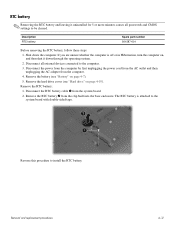
... from the AC outlet and then unplugging the AC adapter from the system board. 2. Description RTC battery Spare part number 501587-001 Before removing the RTC battery, follow these steps: 1. Remove the RTC battery 2 from the clip built into the base enclosure. Remove the hard drive cover (see "Battery" on , and then shut it uninstalled for 5 or more minutes causes all external devices connected to install the RTC battery.
... from the AC outlet and then unplugging the AC adapter from the system board. 2. Description RTC battery Spare part number 501587-001 Before removing the RTC battery, follow these steps: 1. Remove the RTC battery 2 from the clip built into the base enclosure. Remove the hard drive cover (see "Battery" on , and then shut it uninstalled for 5 or more minutes causes all external devices connected to install the RTC battery.
Service Guide
Page 76
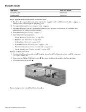
... unsure whether the computer is available using spare part number 496836-001. 2. Keyboard cover (see "Power button board" on page 4-8) b. The Bluetooth cable is off or in Hibernation, turn the computer on page 4-20) e. Removal and replacement procedures 4-35 Display assembly (see "Hard drive" on page 4-23) Remove the Bluetooth module: 1. Hard drive (see "Display assembly" on page 4-10) c. Keyboard (see "Battery" on page 4-17) d. Remove the battery (see "Keyboard" on page 4-7). 5. Shut down through the operating system. 2.
... unsure whether the computer is available using spare part number 496836-001. 2. Keyboard cover (see "Power button board" on page 4-8) b. The Bluetooth cable is off or in Hibernation, turn the computer on page 4-20) e. Removal and replacement procedures 4-35 Display assembly (see "Hard drive" on page 4-23) Remove the Bluetooth module: 1. Hard drive (see "Display assembly" on page 4-10) c. Keyboard (see "Battery" on page 4-17) d. Remove the battery (see "Keyboard" on page 4-7). 5. Shut down through the operating system. 2.
Service Guide
Page 84
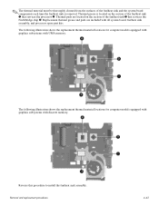
... and pads are located on the section of the fan/heat sink 3 that services the processor 2. Thermal pads are included with UMA memory. Reverse this procedure to install the fan/heat sink assembly. The following illustration shows the replacement thermal material locations for computer models equipped with graphics subsystems with all system board, fan/heat sink assembly, and processor spare part kits. Removal and replacement procedures...
... and pads are located on the section of the fan/heat sink 3 that services the processor 2. Thermal pads are included with UMA memory. Reverse this procedure to install the fan/heat sink assembly. The following illustration shows the replacement thermal material locations for computer models equipped with graphics subsystems with all system board, fan/heat sink assembly, and processor spare part kits. Removal and replacement procedures...

Service Guide
Page 89
... step 1. Restoring default settings in the Setup Utility. While the "Press the ESC key for Startup Menu" message is displayed in the lower-left corner of the screen, press esc. Open the Setup Utility by turning on or restarting the computer. If the Setup Utility is displayed. 3. Open the Setup Utility by turning on or restarting the computer. Setup Utility 5-2 If the Setup Utility is displayed, press f10. 2. To exit the Setup Utility without changing any settings, use the arrow keys to...
... step 1. Restoring default settings in the Setup Utility. While the "Press the ESC key for Startup Menu" message is displayed in the lower-left corner of the screen, press esc. Open the Setup Utility by turning on or restarting the computer. If the Setup Utility is displayed. 3. Open the Setup Utility by turning on or restarting the computer. Setup Utility 5-2 If the Setup Utility is displayed, press f10. 2. To exit the Setup Utility without changing any settings, use the arrow keys to...
Service Guide
Page 91
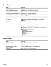
... Network Adapter boot-Enable/disable boot from Internal Network Adapter. ■ Boot Order-Set the boot order for: ❐ USB Floppy ❐ Internal CD/DVD ROM Drive ❐ Hard drive ❐ USB Diskette on Key ❐ USB Hard drive ❐ Network adapter Diagnostics menu Select Hard Disk Self Test Secondary Hard Disk Self Test (select models only) Memory Test To do this menu option is in DC mode. Run a comprehensive self-test on . Enable/disable LAN Power Saving. Setup Utility 5-4 Enable/disable the processor C4 sleep state. Enable/disable Card Reader/1394 Power...
... Network Adapter boot-Enable/disable boot from Internal Network Adapter. ■ Boot Order-Set the boot order for: ❐ USB Floppy ❐ Internal CD/DVD ROM Drive ❐ Hard drive ❐ USB Diskette on Key ❐ USB Hard drive ❐ Network adapter Diagnostics menu Select Hard Disk Self Test Secondary Hard Disk Self Test (select models only) Memory Test To do this menu option is in DC mode. Run a comprehensive self-test on . Enable/disable LAN Power Saving. Setup Utility 5-4 Enable/disable the processor C4 sleep state. Enable/disable Card Reader/1394 Power...
Service Guide
Page 134
... 2-8 BIOS administrator password 5-3 Bluetooth module removal 4-35 spare part number 4-35 Bluetooth module cable 3-17 removal 4-35 spare part number 3-6, 3-17 Blu-ray disc specifications 6-4 Blu-ray ROM DVD±RW SuperMulti DL Drive product description 1-4 removal 4-9 spare part number 4-8 specifications 6-4 boot options 5-4 boot order 5-4 bottom components 2-8 Index Index built-in device Bluetooth device radio 2-8 modem 1-4 wireless button 2-3 WLAN device radio 2-8 buttons power 2-3 wireless 2-3 C cables, service consideration 4-1 caps lock light 2-2 chipset, product description 1-2 CMOS...
... 2-8 BIOS administrator password 5-3 Bluetooth module removal 4-35 spare part number 4-35 Bluetooth module cable 3-17 removal 4-35 spare part number 3-6, 3-17 Blu-ray disc specifications 6-4 Blu-ray ROM DVD±RW SuperMulti DL Drive product description 1-4 removal 4-9 spare part number 4-8 specifications 6-4 boot options 5-4 boot order 5-4 bottom components 2-8 Index Index built-in device Bluetooth device radio 2-8 modem 1-4 wireless button 2-3 WLAN device radio 2-8 buttons power 2-3 wireless 2-3 C cables, service consideration 4-1 caps lock light 2-2 chipset, product description 1-2 CMOS...
Service Guide
Page 135
... 1-4 removal 4-9 spare part number 3-8, 3-12, 3-18, 4-8 specifications 6-3 DVD±RW and CD-RW SuperMulti Double-Layer Combo Drive with LightScribe product description 1-4 removal 4-9 spare part number 3-12, 4-8 specifications 6-4 E electrostatic discharge 4-2 esc key 2-4 Ethernet, product description 1-4 external media cards, product description 1-5 external monitor port location 2-7 pin assignments 9-2 F f11 recovery 8-4 factory state, recovering to 8-1 fan removal 4-41 spare part number 3-4, 3-15, 4-41 feet locations 4-6 spare part number 4-6 fn key 2-4 front components 2-6 function keys...
... 1-4 removal 4-9 spare part number 3-8, 3-12, 3-18, 4-8 specifications 6-3 DVD±RW and CD-RW SuperMulti Double-Layer Combo Drive with LightScribe product description 1-4 removal 4-9 spare part number 3-12, 4-8 specifications 6-4 E electrostatic discharge 4-2 esc key 2-4 Ethernet, product description 1-4 external media cards, product description 1-5 external monitor port location 2-7 pin assignments 9-2 F f11 recovery 8-4 factory state, recovering to 8-1 fan removal 4-41 spare part number 3-4, 3-15, 4-41 feet locations 4-6 spare part number 4-6 fn key 2-4 front components 2-6 function keys...
Service Guide
Page 137
...part number 3-10, 3-15, 7-1 screw listing 7-1 security cable slot 2-7 Security menu BIOS administrator password 5-3 Power-On password 5-3 security, product description 1-5 serial number 3-1, 4-5 serviceability, product description 1-6 Index Setup Utility accessing 5-1 changing the language 5-1 Diagnostics menu 5-4 displaying system information 5-2 exiting 5-3 Main menu 5-3 navigating and selecting 5-2 restoring default settings 5-2 System Configuration menu 5-4 speaker removal 4-36 spare part number 3-5, 3-17, 4-36 specifications Blu-ray ROM DVD±RW SuperMulti DL Drive 6-4 display 6-2 DVD...
...part number 3-10, 3-15, 7-1 screw listing 7-1 security cable slot 2-7 Security menu BIOS administrator password 5-3 Power-On password 5-3 security, product description 1-5 serial number 3-1, 4-5 serviceability, product description 1-6 Index Setup Utility accessing 5-1 changing the language 5-1 Diagnostics menu 5-4 displaying system information 5-2 exiting 5-3 Main menu 5-3 navigating and selecting 5-2 restoring default settings 5-2 System Configuration menu 5-4 speaker removal 4-36 spare part number 3-5, 3-17, 4-36 specifications Blu-ray ROM DVD±RW SuperMulti DL Drive 6-4 display 6-2 DVD...


