
Maintenance and Service Guide
Page 5
... Packaging and transporting guidelines 21 Workstation guidelines 21 5 Removal and replacement procedures for Authorized Service Provider parts 23 Component replacement procedures ...23 Bottom cover ...23 Battery ...25 SSD drive ...26 v
... Packaging and transporting guidelines 21 Workstation guidelines 21 5 Removal and replacement procedures for Authorized Service Provider parts 23 Component replacement procedures ...23 Bottom cover ...23 Battery ...25 SSD drive ...26 v

Maintenance and Service Guide
Page 10
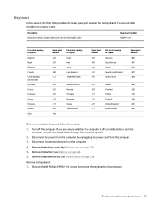
...requirements Security Operating system Description Integrated dual-array microphone Ethernet available from docking stations; USB 3.1, DP, PD, Thunderbolt) Headphone/Microphone Combo HP ZBook 65/150/200 W Thunderbolt 3 Dock Keyboard Dura keys, backlit ClickPad Gestures enabled by default Taps enabled by way of M.2 ...options by default On/off LED AC adapter 45-W HP Smart AC adapter non-PFC USB-C Power cord Duck head power cord with 2-prong adapter (South Korea uses 3-pin duck head) Battery 4-cell, 38-Whr, 5.0 Ahr long life polymer battery Trusted Platform Module (TPM) 2.0 (Infineon, soldered ...
...requirements Security Operating system Description Integrated dual-array microphone Ethernet available from docking stations; USB 3.1, DP, PD, Thunderbolt) Headphone/Microphone Combo HP ZBook 65/150/200 W Thunderbolt 3 Dock Keyboard Dura keys, backlit ClickPad Gestures enabled by default Taps enabled by way of M.2 ...options by default On/off LED AC adapter 45-W HP Smart AC adapter non-PFC USB-C Power cord Duck head power cord with 2-prong adapter (South Korea uses 3-pin duck head) Battery 4-cell, 38-Whr, 5.0 Ahr long life polymer battery Trusted Platform Module (TPM) 2.0 (Infineon, soldered ...
Maintenance and Service Guide
Page 17
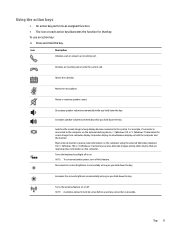
... key. Increases speaker volume incrementally while you hold the key. Declines an incoming call or ends the current call . Mutes the microphone. NOTE: To conserve battery power, turn off .
... key. Increases speaker volume incrementally while you hold the key. Declines an incoming call or ends the current call . Mutes the microphone. NOTE: To conserve battery power, turn off .
Maintenance and Service Guide
Page 19
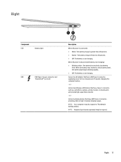
...- NOTE: Your computer may be required. When the battery has reached a critical battery level, the battery light begins blinking rapidly. ● Off: The battery is disconnected (battery not charging): ● Blinking amber: The battery has reached a low battery level. NOTE: Adapters (purchased separately) may also support... Description When AC power is connected: ● White: The battery charge is greater than 90 percent. ● Amber: The battery charge is from 0 to the computer and, if needed, charging the computer battery. - Right 11 or - Connect an AC adapter that has ...
...- NOTE: Your computer may be required. When the battery has reached a critical battery level, the battery light begins blinking rapidly. ● Off: The battery is disconnected (battery not charging): ● Blinking amber: The battery has reached a low battery level. NOTE: Adapters (purchased separately) may also support... Description When AC power is connected: ● White: The battery charge is greater than 90 percent. ● Amber: The battery charge is from 0 to the computer and, if needed, charging the computer battery. - Right 11 or - Connect an AC adapter that has ...
Maintenance and Service Guide
Page 21
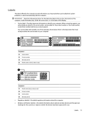
... serial number, and possibly for use. Refer to the illustration that most closely matches the service label on the back of the computer, inside the battery bay, under the service door, or on your computer. When contacting support, you contact support. Labels The labels affixed to identify your computer.
... serial number, and possibly for use. Refer to the illustration that most closely matches the service label on the back of the computer, inside the battery bay, under the service door, or on your computer. When contacting support, you contact support. Labels The labels affixed to identify your computer.
Maintenance and Service Guide
Page 24
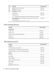
...-C to -edge glass. 857630-001 Thermal solution kit (includes thermal plate, three graphite sheets, and three thermal pads; Item (9) (10) (11) Component Spare part number Battery (4-cell, 38-Wh, 1.89-Ah, Li ion) 828226-005 Audio board (includes cable) 850911-001 Bottom cover (includes feet) Standard models 850905-001 Lightweight models...
...-C to -edge glass. 857630-001 Thermal solution kit (includes thermal plate, three graphite sheets, and three thermal pads; Item (9) (10) (11) Component Spare part number Battery (4-cell, 38-Wh, 1.89-Ah, Li ion) 828226-005 Audio board (includes cable) 850911-001 Bottom cover (includes feet) Standard models 850905-001 Lightweight models...
Maintenance and Service Guide
Page 33
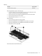
... then shut it down through the operating system. 2. Disconnect the battery cable from the computer. 4. Remove the two Phillips PM1.6×4.0 screws (2) that secure the battery to the computer. 4. Remove the battery: 1. Lift the battery out of the computer (4). Turn off or in Hibernation, turn...to the computer. 3. Disconnect the power from the computer by unplugging the power cord from the computer. 3. Battery Description 4-cell, 38-Wh, 1.89-Ah, Li ion battery Spare part number 828226-005 Before disassembling the computer, follow these steps: 1. Remove the six Phillips PM2.0×...
... then shut it down through the operating system. 2. Disconnect the battery cable from the computer. 4. Remove the two Phillips PM1.6×4.0 screws (2) that secure the battery to the computer. 4. Remove the battery: 1. Lift the battery out of the computer (4). Turn off or in Hibernation, turn...to the computer. 3. Disconnect the power from the computer by unplugging the power cord from the computer. 3. Battery Description 4-cell, 38-Wh, 1.89-Ah, Li ion battery Spare part number 828226-005 Before disassembling the computer, follow these steps: 1. Remove the six Phillips PM2.0×...

Maintenance and Service Guide
Page 34
... in Hibernation, turn the computer on, and then shut it away from the computer. 4. Remove the bottom cover (see Battery on page 23). 5. Reverse this procedure to the system board. 2. Disconnect the battery cable (see Bottom cover on page 25). Remove the Phillips PM2.0×3.0 screw (1) that secures the drive to install...
... in Hibernation, turn the computer on, and then shut it away from the computer. 4. Remove the bottom cover (see Battery on page 23). 5. Reverse this procedure to the system board. 2. Disconnect the battery cable (see Bottom cover on page 25). Remove the Phillips PM2.0×3.0 screw (1) that secures the drive to install...
Maintenance and Service Guide
Page 35
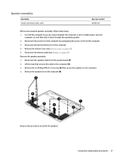
Remove the bottom cover (see Battery on page 23). 5. Lift the tape that secure the speakers to the computer. 4. Component replacement procedures 27 Disconnect the power from the computer by unplugging ... part number 850906-001 Before removing the speaker assembly, follow these steps: 1. Remove the speaker assembly: 1. Disconnect the speaker cable from the computer. 3. Disconnect the battery cable (see Bottom cover on page 25). Remove the six Phillips PM2.0×3.0 screws (3) that secures the cable to install the speakers. If you are...
Remove the bottom cover (see Battery on page 23). 5. Lift the tape that secure the speakers to the computer. 4. Component replacement procedures 27 Disconnect the power from the computer by unplugging ... part number 850906-001 Before removing the speaker assembly, follow these steps: 1. Remove the speaker assembly: 1. Disconnect the speaker cable from the computer. 3. Disconnect the battery cable (see Bottom cover on page 25). Remove the six Phillips PM2.0×3.0 screws (3) that secures the cable to install the speakers. If you are...
Maintenance and Service Guide
Page 36
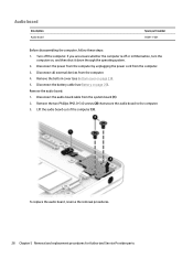
...from the computer. 4. Disconnect all external devices from the system board (1). 2. Remove the audio board: 1. Remove the bottom cover (see Battery on page 25). To replace the audio board, reverse the removal procedures. 28 Chapter 5 Removal and replacement procedures for Authorized Service Provider parts ...Remove the two Phillips PM2.0×3.0 screws (2) that secure the audio board to the computer. 3. Disconnect the battery cable (see Bottom cover on , and then shut it down through the operating system. 2. Lift the audio board out of the ...
...from the computer. 4. Disconnect all external devices from the system board (1). 2. Remove the audio board: 1. Remove the bottom cover (see Battery on page 25). To replace the audio board, reverse the removal procedures. 28 Chapter 5 Removal and replacement procedures for Authorized Service Provider parts ...Remove the two Phillips PM2.0×3.0 screws (2) that secure the audio board to the computer. 3. Disconnect the battery cable (see Bottom cover on , and then shut it down through the operating system. 2. Lift the audio board out of the ...
Maintenance and Service Guide
Page 37
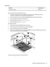
...whether the computer is off the computer. Disconnect all external devices from the system board. 2. Remove the bottom cover (see Battery on page 25). Turn off or in Hibernation, turn the computer on page 23). 5. Lift the cable from the adhesive... TouchPad: 1. Disconnect the TouchPad cable (1) from the computer. 4. Reverse the removal procedures to the battery (2). 3. Component replacement procedures 29 Remove the adhesive from the computer. 3. Remove the battery (see Bottom cover on , and then shut it to install the TouchPad. TouchPad Description TouchPad (includes...
...whether the computer is off the computer. Disconnect all external devices from the system board. 2. Remove the bottom cover (see Battery on page 25). Turn off or in Hibernation, turn the computer on page 23). 5. Lift the cable from the adhesive... TouchPad: 1. Disconnect the TouchPad cable (1) from the computer. 4. Reverse the removal procedures to the battery (2). 3. Component replacement procedures 29 Remove the adhesive from the computer. 3. Remove the battery (see Bottom cover on , and then shut it to install the TouchPad. TouchPad Description TouchPad (includes...
Maintenance and Service Guide
Page 38
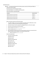
... system board and installed on the replacement system board: ● SSD drive module (see Bottom cover on page 26) Remove the system board: 1. Remove the battery (see Battery on , and then shut it down through the operating system. 2. System board NOTE: The system board spare part kit includes a processor, heat sink, 8 GB...
... system board and installed on the replacement system board: ● SSD drive module (see Bottom cover on page 26) Remove the system board: 1. Remove the battery (see Battery on , and then shut it down through the operating system. 2. System board NOTE: The system board spare part kit includes a processor, heat sink, 8 GB...
Maintenance and Service Guide
Page 40
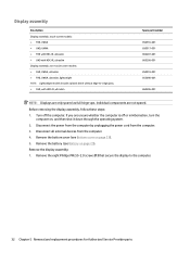
... computer by unplugging the power cord from the computer. 4. Individual components are only spared as full hinge-ups. Remove the bottom cover (see Battery on page 25). Remove the display assembly: 1. Display assembly Description Display assembly, touch screen models: ● FHD, UWVA ● UHD,... 5 Removal and replacement procedures for Authorized Service Provider parts Disconnect all external devices from the computer. 3. Remove the battery (see Bottom cover on , and then shut it down through the operating system. 2. Before removing the display assembly, follow these steps: 1....
... computer by unplugging the power cord from the computer. 4. Individual components are only spared as full hinge-ups. Remove the bottom cover (see Battery on page 25). Remove the display assembly: 1. Display assembly Description Display assembly, touch screen models: ● FHD, UWVA ● UHD,... 5 Removal and replacement procedures for Authorized Service Provider parts Disconnect all external devices from the computer. 3. Remove the battery (see Bottom cover on , and then shut it down through the operating system. 2. Before removing the display assembly, follow these steps: 1....
Maintenance and Service Guide
Page 45
... is off the computer. Disconnect the power from the computer by unplugging the power cord from the computer. 4. Remove the battery (see System board on page 25). 6. Remove the system board (see Battery on page 30). Remove the bottom cover (see Bottom cover on , and then shut it down through the operating...
... is off the computer. Disconnect the power from the computer by unplugging the power cord from the computer. 4. Remove the battery (see System board on page 25). 6. Remove the system board (see Battery on page 30). Remove the bottom cover (see Bottom cover on , and then shut it down through the operating...

Maintenance and Service Guide
Page 49
Position the battery upright. Component replacement procedures 41 6. Replace the Mylar insulator (1) (911281-001) on the inside of the battery. 9. Add graphite sheets (1) (911287-001) and (2) (911288-001) on the bottom of the bottom cover. 7. Position the battery upside down. 8.
Position the battery upright. Component replacement procedures 41 6. Replace the Mylar insulator (1) (911281-001) on the inside of the battery. 9. Add graphite sheets (1) (911287-001) and (2) (911288-001) on the bottom of the bottom cover. 7. Position the battery upside down. 8.
Maintenance and Service Guide
Page 50
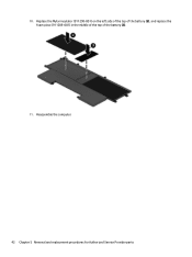
Reassemble the computer. 42 Chapter 5 Removal and replacement procedures for Authorized Service Provider parts 10. Replace the Mylar insulator (911290-001) on the left side of the top of the battery (2), and replace the foam piece (911289-001) in the middle of the top of the battery (3). 11.
Reassemble the computer. 42 Chapter 5 Removal and replacement procedures for Authorized Service Provider parts 10. Replace the Mylar insulator (911290-001) on the left side of the top of the battery (2), and replace the foam piece (911289-001) in the middle of the top of the battery (3). 11.

Maintenance and Service Guide
Page 53
...BIOS versions, see Downloading a BIOS update on your changes, select the Exit icon in the taskbar search box, and then select the HP Support Assistant app. - BIOS version information (also known as ROM date and System BIOS) can be available on -screen instructions to download... your hard drive where the BIOS update is connected to the location on battery power, docked in compressed files called SoftPaqs. Follow the on the HP website. Using Computer Setup 45 See Starting Computer Setup on -screen instructions. 4. Updating the BIOS ...
...BIOS versions, see Downloading a BIOS update on your changes, select the Exit icon in the taskbar search box, and then select the HP Support Assistant app. - BIOS version information (also known as ROM date and System BIOS) can be available on -screen instructions to download... your hard drive where the BIOS update is connected to the location on battery power, docked in compressed files called SoftPaqs. Follow the on the HP website. Using Computer Setup 45 See Starting Computer Setup on -screen instructions. 4. Updating the BIOS ...

Maintenance and Service Guide
Page 58
...3. Do not shut down the computer or initiate Sleep. At the download area, follow these instructions: Do not disconnect power on the HP website. or - You may be revealed by pressing fn+esc (if you connect your selection to locate the update later, after the ...on-screen instructions. - Select Updates and tune-ups, and then select Check for HP updates now. 3. BIOS installation procedures vary. If the update is more recent than those currently installed on battery power, docked in compressed files called SoftPaqs. During the download and installation, follow ...
...3. Do not shut down the computer or initiate Sleep. At the download area, follow these instructions: Do not disconnect power on the HP website. or - You may be revealed by pressing fn+esc (if you connect your selection to locate the update later, after the ...on-screen instructions. - Select Updates and tune-ups, and then select Check for HP updates now. 3. BIOS installation procedures vary. If the update is more recent than those currently installed on battery power, docked in compressed files called SoftPaqs. During the download and installation, follow ...
Maintenance and Service Guide
Page 64
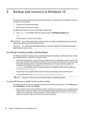
... Assistant app. ‒ or - For more information, see Recovering using the recovery media, see Creating HP Recovery media (select products only) on a tablet, the tablet battery must be used to the HP support assistant app. ▲ Type support in cases where the hard drive is disabled by default. NOTE: If storage is 32...
... Assistant app. ‒ or - For more information, see Recovering using the recovery media, see Creating HP Recovery media (select products only) on a tablet, the tablet battery must be used to the HP support assistant app. ▲ Type support in cases where the hard drive is disabled by default. NOTE: If storage is 32...

Maintenance and Service Guide
Page 78
... and exit, and then select Shutdown. h. Select the Main menu, select Apply Factory Defaults and Exit, select Yes to proceed. l. Remove all power and system batteries for Startup Menu" message is set, select the Security menu, and scroll down to Hard Drive Utilities under the Utilities menu. NOTE: If you clear...
... and exit, and then select Shutdown. h. Select the Main menu, select Apply Factory Defaults and Exit, select Yes to proceed. l. Remove all power and system batteries for Startup Menu" message is set, select the Security menu, and scroll down to Hard Drive Utilities under the Utilities menu. NOTE: If you clear...


