
Service Guide
Page 6
... 48 Unknown user password 49 Component replacement procedures 50 Service tag ...50 Computer feet ...51 Battery ...52 Webcam/microphone module 53 Optical drive ...55 TV tuner module ...57 RTC battery ...59 Memory module ...60 Hard drive ...62 WLAN module ...65 Switch cover and keyboard 69 Power button board ...73 Speaker assembly ...74 Bluetooth module ...75 Display assembly ...76 Top cover ...84 Modem module ...87 Audio/infrared board ...89 USB board ...90 System board ...92 TV tuner module cable ...94 Modem module cable ...95 Power connector cable ...96 Fan/heat...
... 48 Unknown user password 49 Component replacement procedures 50 Service tag ...50 Computer feet ...51 Battery ...52 Webcam/microphone module 53 Optical drive ...55 TV tuner module ...57 RTC battery ...59 Memory module ...60 Hard drive ...62 WLAN module ...65 Switch cover and keyboard 69 Power button board ...73 Speaker assembly ...74 Bluetooth module ...75 Display assembly ...76 Top cover ...84 Modem module ...87 Audio/infrared board ...89 USB board ...90 System board ...92 TV tuner module cable ...94 Modem module cable ...95 Power connector cable ...96 Fan/heat...
Service Guide
Page 17
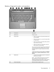
... power settings, select Start > Control Panel > System and Maintenance > Power Options. ● Launches the QuickPlay program (for more information. If the computer has stopped responding and Windows® shutdown procedures are ineffective, press and hold the power button for at least 5 seconds to turn on the computer. ● When the computer is on . Buttons, fingerprint reader, and speakers Item (1) (2) Component Speakers (2) Power button* (3) Media button (4) Volume mute button Description Produce sound...
... power settings, select Start > Control Panel > System and Maintenance > Power Options. ● Launches the QuickPlay program (for more information. If the computer has stopped responding and Windows® shutdown procedures are ineffective, press and hold the power button for at least 5 seconds to turn on the computer. ● When the computer is on . Buttons, fingerprint reader, and speakers Item (1) (2) Component Speakers (2) Power button* (3) Media button (4) Volume mute button Description Produce sound...
Service Guide
Page 18
... about changing factory settings, refer to the user guides located in order to establish a wireless connection. (11) Fingerprint reader Allows a fingerprint logon to Windows, instead of a password logon. *This table describes factory settings. You can also tap the minus sign on the scroll zone to decrease volume, or tap the plus sign on the scroll zone to increase volume. NOTE: A wireless network must be set up in Help and Support. 10 Chapter 2 External...
... about changing factory settings, refer to the user guides located in order to establish a wireless connection. (11) Fingerprint reader Allows a fingerprint logon to Windows, instead of a password logon. *This table describes factory settings. You can also tap the minus sign on the scroll zone to decrease volume, or tap the plus sign on the scroll zone to increase volume. NOTE: A wireless network must be set up in Help and Support. 10 Chapter 2 External...
Service Guide
Page 22
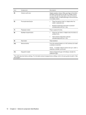
... 2 External component identification Rear components Component Vents (2) Function Enables airflow to optical discs. Right-side components Item (1) (2) (3) (4) Component Optical drive light Optical drive USB ports (2) TV antenna jack (select models only) (5) RJ-11 (modem) jack (select models only) (6) Security cable slot (7) Power connector Function Blinking: The optical drive is normal for the internal fan to act as a deterrent, but it may not prevent the computer from being accessed. Connects a TV antenna, a digital cable device, or a satellite device...
... 2 External component identification Rear components Component Vents (2) Function Enables airflow to optical discs. Right-side components Item (1) (2) (3) (4) Component Optical drive light Optical drive USB ports (2) TV antenna jack (select models only) (5) RJ-11 (modem) jack (select models only) (6) Security cable slot (7) Power connector Function Blinking: The optical drive is normal for the internal fan to act as a deterrent, but it may not prevent the computer from being accessed. Connects a TV antenna, a digital cable device, or a satellite device...
Service Guide
Page 23
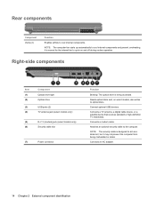
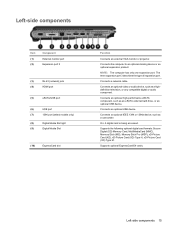
... term expansion port 3 describes the type of expansion port. On: A digital card is being accessed. NOTE: The computer has only one expansion port. Connects an optional video or audio device, such as a camcorder. Supports optional ExpressCard/54 cards. Left-side components Item (1) (2) Component External monitor port Expansion port 3 (3) RJ-45 (network) jack (4) HDMI port (5) eSATA/USB port (6) USB port (7) 1394 port (select models only) (8) Digital Media Slot light (9) Digital Media Slot (10) ExpressCard slot Function Connects an external VGA monitor or...
... term expansion port 3 describes the type of expansion port. On: A digital card is being accessed. NOTE: The computer has only one expansion port. Connects an optional video or audio device, such as a camcorder. Supports optional ExpressCard/54 cards. Left-side components Item (1) (2) Component External monitor port Expansion port 3 (3) RJ-45 (network) jack (4) HDMI port (5) eSATA/USB port (6) USB port (7) 1394 port (select models only) (8) Digital Media Slot light (9) Digital Media Slot (10) ExpressCard slot Function Connects an external VGA monitor or...
Service Guide
Page 25
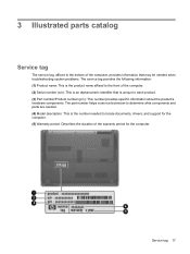
... and parts are needed. (4) Model description: This is the number needed when troubleshooting system problems. The service tag provides the following information: (1) Product name: This is unique to the front of the warranty period for the computer. 3 Illustrated parts catalog Service tag The service tag, affixed to the bottom of the computer, provides information that may be needed to locate documents, drivers, and support for...
... and parts are needed. (4) Model description: This is the number needed when troubleshooting system problems. The service tag provides the following information: (1) Product name: This is unique to the front of the warranty period for the computer. 3 Illustrated parts catalog Service tag The service tag, affixed to the bottom of the computer, provides information that may be needed to locate documents, drivers, and support for...

Service Guide
Page 57
... passwords and all external devices connected to the computer. 3. If you are unsure whether the computer is off or in Hibernation, turn the computer on page 59). 6. Remove the RTC battery (see Battery on the computer. Wait approximately 5 minutes. 7. Replace the RTC battery and reassemble the computer. 8. Disconnect all CMOS settings have been cleared. Do not reinsert any batteries at this time. 9. Unknown user password If...
... passwords and all external devices connected to the computer. 3. If you are unsure whether the computer is off or in Hibernation, turn the computer on page 59). 6. Remove the RTC battery (see Battery on the computer. Wait approximately 5 minutes. 7. Replace the RTC battery and reassemble the computer. 8. Disconnect all CMOS settings have been cleared. Do not reinsert any batteries at this time. 9. Unknown user password If...
Service Guide
Page 58
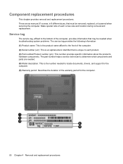
... be needed when troubleshooting system problems. The service tag provides the following information: (1) Product name: This is the product name affixed to locate documents, drivers, and support for the computer. 50 Chapter 4 Removal and replacement procedures Make special note of the computer, provides information that is the number needed . (4) Model description: This is unique to the bottom of each product. (3) Part number/Product number (p/n): This number provides specific...
... be needed when troubleshooting system problems. The service tag provides the following information: (1) Product name: This is the product name affixed to locate documents, drivers, and support for the computer. 50 Chapter 4 Removal and replacement procedures Make special note of the computer, provides information that is the number needed . (4) Model description: This is unique to the bottom of each product. (3) Part number/Product number (p/n): This number provides specific...

Service Guide
Page 68
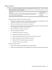
... 484268-001 1024-MB 512-MB 484267-001 484266-001 Before removing the memory module, follow these steps: 1. Lift the left edge of the memory module slot to the computer. 3. Remove the battery (see Battery on page 52). Disconnect all external devices connected to the computer. 3. Memory module Description Spare part number For use only with computer models equipped with AMD processors (667-MHz, PC2-5300, 1-DIMM): 2048...
... 484268-001 1024-MB 512-MB 484267-001 484266-001 Before removing the memory module, follow these steps: 1. Lift the left edge of the memory module slot to the computer. 3. Remove the battery (see Battery on page 52). Disconnect all external devices connected to the computer. 3. Memory module Description Spare part number For use only with computer models equipped with AMD processors (667-MHz, PC2-5300, 1-DIMM): 2048...
Service Guide
Page 95
... computer. 3. Remove the battery (see Speaker assembly on page 55). Remove the following components: a. Hard drive (see Switch cover and keyboard on page 31 for use only in the Cable Kit, spare part number 501891-001. Switch cover and keyboard (see Hard drive on page 52). 5. d. See Cable Kit on page 69). Shut down through the operating system. 2. The modem module cable is off or in all external devices connected to the system board. If...
... computer. 3. Remove the battery (see Speaker assembly on page 55). Remove the following components: a. Hard drive (see Switch cover and keyboard on page 31 for use only in the Cable Kit, spare part number 501891-001. Switch cover and keyboard (see Hard drive on page 52). 5. d. See Cable Kit on page 69). Shut down through the operating system. 2. The modem module cable is off or in all external devices connected to the system board. If...
Service Guide
Page 108
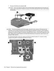
The following illustration shows the replacement thermal material locations for computer models equipped with graphics subsystems with all fan/heat sink assembly, system board, and processor spare part kits. Thermal paste is used on the processor (1) and the heat sink section (2) that service them. Thermal pads are used on the Northbridge chip (3), the graphics subsystem chip (4), and the sections of the...
The following illustration shows the replacement thermal material locations for computer models equipped with graphics subsystems with all fan/heat sink assembly, system board, and processor spare part kits. Thermal paste is used on the processor (1) and the heat sink section (2) that service them. Thermal pads are used on the Northbridge chip (3), the graphics subsystem chip (4), and the sections of the...
Service Guide
Page 111
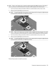
... (2) straight up and remove it . Turn the processor locking screw (1) one -half turn counterclockwise until you install the processor. Lift the processor (2) straight up and remove it . Reverse this procedure to computer models equipped with Intel processors. 1. NOTE: Steps 1 and 2 apply only to install the processor. See steps 1 and 2 for processor removal information for computer models equipped with AMD processors...
... (2) straight up and remove it . Turn the processor locking screw (1) one -half turn counterclockwise until you install the processor. Lift the processor (2) straight up and remove it . Reverse this procedure to computer models equipped with Intel processors. 1. NOTE: Steps 1 and 2 apply only to install the processor. See steps 1 and 2 for processor removal information for computer models equipped with AMD processors...
Service Guide
Page 114
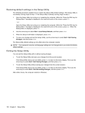
... the screen, press esc. While the "Press the ESC key for Startup Menu" message is displayed in Windows. 106 Chapter 5 Setup Utility NOTE: Your password, security, and language settings are not visible, press esc to return to select Exit > Exit Discarding Changes, and then press enter. Open the Setup Utility by turning on or restarting the computer. When the Startup Menu is displayed, press enter. 4. Then use the arrow keys to the menu display.
... the screen, press esc. While the "Press the ESC key for Startup Menu" message is displayed in Windows. 106 Chapter 5 Setup Utility NOTE: Your password, security, and language settings are not visible, press esc to return to select Exit > Exit Discarding Changes, and then press enter. Open the Setup Utility by turning on or restarting the computer. When the Startup Menu is displayed, press enter. 4. Then use the arrow keys to the menu display.
Service Guide
Page 115
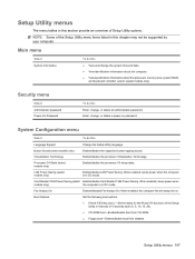
...C4 sleep state. Enable/disable LAN Power Saving. Security menu Select Administrator password Power-On Password To do this section provide an overview of the Setup Utility in DC mode. Button Sound (select models only) Virtualization Technology Processor C4 State (select models only) LAN Power Saving (select models only) Enable/disable the capacitive button tapping sound. Card Reader/1394 Power Saving (select Enable/disable Card Reader/1394 Power Saving. When enabled, the computer fan will always be supported by your computer. Boot Options Set the following boot options: ●...
...C4 sleep state. Enable/disable LAN Power Saving. Security menu Select Administrator password Power-On Password To do this section provide an overview of the Setup Utility in DC mode. Button Sound (select models only) Virtualization Technology Processor C4 State (select models only) LAN Power Saving (select models only) Enable/disable the capacitive button tapping sound. Card Reader/1394 Power Saving (select Enable/disable Card Reader/1394 Power Saving. When enabled, the computer fan will always be supported by your computer. Boot Options Set the following boot options: ●...
Service Guide
Page 116
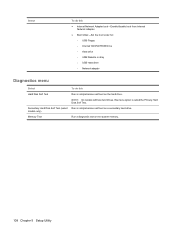
... on the hard drive. models only) Memory Test Run a diagnostic test on a secondary hard drive. Secondary Hard Disk Self Test (select Run a comprehensive self-test on the system memory. 108 Chapter 5 Setup Utility Select To do this ● Internal Network Adapter boot―Enable/disable boot from Internal Network Adapter. ● Boot Order―Set the boot order for: ◦ USB Floppy ◦ Internal CD/DVD ROM Drive ◦ Hard drive ◦ USB Diskette on Key ◦ USB Hard drive ◦ Network adapter Diagnostics menu Select To do this menu option is called...
... on the hard drive. models only) Memory Test Run a diagnostic test on a secondary hard drive. Secondary Hard Disk Self Test (select Run a comprehensive self-test on the system memory. 108 Chapter 5 Setup Utility Select To do this ● Internal Network Adapter boot―Enable/disable boot from Internal Network Adapter. ● Boot Order―Set the boot order for: ◦ USB Floppy ◦ Internal CD/DVD ROM Drive ◦ Hard drive ◦ USB Diskette on Key ◦ USB Hard drive ◦ Network adapter Diagnostics menu Select To do this menu option is called...

Service Guide
Page 120
... support for details. 112 Chapter 6 Specifications Actual accessible capacity is less. NOTE: Certain restrictions and exclusions apply. Hard drive specifications 320-GB* 250-GB* 160-GB* 120-GB* Dimensions Height 9.5 mm 9.5 mm 9.5 mm 9.5 mm Width 70 mm Weight 101 g Interface type ATA-7 Transfer rate Synchronous (maximum) 100 MB/sec Security ATA security Seek times (typical read, including setting...
... support for details. 112 Chapter 6 Specifications Actual accessible capacity is less. NOTE: Certain restrictions and exclusions apply. Hard drive specifications 320-GB* 250-GB* 160-GB* 120-GB* Dimensions Height 9.5 mm 9.5 mm 9.5 mm 9.5 mm Width 70 mm Weight 101 g Interface type ATA-7 Transfer rate Synchronous (maximum) 100 MB/sec Security ATA security Seek times (typical read, including setting...
Service Guide
Page 168
... 45 Card Reader Power Saving 107 carrying case, spare part numbers 34, 35 CAT5E cable, spare part number 34, 36 changing the Setup Utility language 105 chipset, product description 1 CMOS clearing 49 components bottom 16 buttons 9 display 7 fingerprint reader 9 front 13 keyboard 11 left-side 15 rear 14 right-side 14 speakers 9 top 7 TouchPad 12 computer feet locations 51 spare part number 51 computer specifications 109 connectors, service considerations 45 D Digital Media Slot 15 Digital Media Slot Light...
... 45 Card Reader Power Saving 107 carrying case, spare part numbers 34, 35 CAT5E cable, spare part number 34, 36 changing the Setup Utility language 105 chipset, product description 1 CMOS clearing 49 components bottom 16 buttons 9 display 7 fingerprint reader 9 front 13 keyboard 11 left-side 15 rear 14 right-side 14 speakers 9 top 7 TouchPad 12 computer feet locations 51 spare part number 51 computer specifications 109 connectors, service considerations 45 D Digital Media Slot 15 Digital Media Slot Light...
Service Guide
Page 169
... display switch 7 displaying system information 105 docking support, product description 5 drive light 13 drives boot order 107 preventing damage 45 DVD±RW and CD-RW Combo Drive precautions 45 removal 55 spare part numbers 22, 33, 38, 55 specifications 114 E electrostatic discharge 46 eSATA/USB port 15 esc key 11 Ethernet, product description 4 exiting the Setup Utility 106 expansion port 3 15 ExpressCard slot 15 ExpressCard slot bezel, illustrated 30 external media cards, product description 5 external monitor port location 15...
... display switch 7 displaying system information 105 docking support, product description 5 drive light 13 drives boot order 107 preventing damage 45 DVD±RW and CD-RW Combo Drive precautions 45 removal 55 spare part numbers 22, 33, 38, 55 specifications 114 E electrostatic discharge 46 eSATA/USB port 15 esc key 11 Ethernet, product description 4 exiting the Setup Utility 106 expansion port 3 15 ExpressCard slot 15 ExpressCard slot bezel, illustrated 30 external media cards, product description 5 external monitor port location 15...
Service Guide
Page 170
... function 11 Windows applications 11 Windows logo 11 L LAN Power Saving 107 language support 107 left-side components 15 lights battery 13 Digital Media Slot 15 drive 13 optical drive 14 power 13 M mass storage devices, spare part numbers 32 media button 9 memory map specifications 123, 124, 125 memory module product description 2 removal 60 spare part numbers 22, 39, 60 memory module compartment 16 memory module compartment cover illustrated 30 removal 60 memory test 108 microphone locations 8 product description 4 microphone jack location 13 pin assignments 147 Mini Card module...
... function 11 Windows applications 11 Windows logo 11 L LAN Power Saving 107 language support 107 left-side components 15 lights battery 13 Digital Media Slot 15 drive 13 optical drive 14 power 13 M mass storage devices, spare part numbers 32 media button 9 memory map specifications 123, 124, 125 memory module product description 2 removal 60 spare part numbers 22, 39, 60 memory module compartment 16 memory module compartment cover illustrated 30 removal 60 memory test 108 microphone locations 8 product description 4 microphone jack location 13 pin assignments 147 Mini Card module...
Service Guide
Page 171
removal 102 spare part numbers 20, 38, 39, 102 Processor C4 State 107 product description audio 4 chipset 1 display panel 2 docking support 5 Ethernet 4 external media cards 5 graphics 2 hard drives 3 keyboard 6 memory module 2 microphone 4 modem 4 operating system 6 optical drives 3 pointing device 6 ports 5 power requirements 6 processors 1 product name 1 security 6 serviceability 6 TV tuner 5 webcam 4 wireless 4 product name 1 R rear components 14 recovering a program or driver 142 recovering from the dedicated recovery partition 146 recovering from the recovery discs 146 recovery 146 ...
removal 102 spare part numbers 20, 38, 39, 102 Processor C4 State 107 product description audio 4 chipset 1 display panel 2 docking support 5 Ethernet 4 external media cards 5 graphics 2 hard drives 3 keyboard 6 memory module 2 microphone 4 modem 4 operating system 6 optical drives 3 pointing device 6 ports 5 power requirements 6 processors 1 product name 1 security 6 serviceability 6 TV tuner 5 webcam 4 wireless 4 product name 1 R rear components 14 recovering a program or driver 142 recovering from the dedicated recovery partition 146 recovering from the recovery discs 146 recovery 146 ...


