
HP Printers - Supported Citrix Presentation Server environments
Page 21
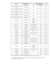
PS N/A N/A N/A N/A N/A N/A N/A N/A N/A N/A N/A N/A N/A N/A N/A N/A N/A N/A N/A N/A N/A N/A N/A N/A ** 7550, 7900, 8400 and 8700 are PCL3 devices but use 3 cartridge print assemblies which are also supported. HP printer Photosmart C4100 All-in-One series Supported in Citrix environment Not Supported HP-supported drivers* PCL Host-based N/A N/A Photosmart C5100 All-in-One series Not Supported N/A N/A Photosmart C6100 All-in-One series Not Supported...
PS N/A N/A N/A N/A N/A N/A N/A N/A N/A N/A N/A N/A N/A N/A N/A N/A N/A N/A N/A N/A N/A N/A N/A N/A ** 7550, 7900, 8400 and 8700 are PCL3 devices but use 3 cartridge print assemblies which are also supported. HP printer Photosmart C4100 All-in-One series Supported in Citrix environment Not Supported HP-supported drivers* PCL Host-based N/A N/A Photosmart C5100 All-in-One series Not Supported N/A N/A Photosmart C6100 All-in-One series Not Supported...
Service Manual
Page 7
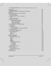
5 Functional Overview (more ' HP DesignJet 200/220 Service Manual) Introduction 5Ć2 Loading Sheet Media 5Ć2 Loading Roll Media on the DesignJet 330 and 350C 5Ć4 Roll Media 5Ć5 Removing Static Charge from the Media 5Ć5 Gripping the Media 5Ć5... and Media Edges 5Ć7 Line Sensor 5Ć7 Providing Ink 5Ć7 Print Cartridges 5Ć7 Distance between Carriage and Media 5Ć7 Producing an Image 5Ć8 PrintĆMode Characteristics 5Ć8 Servicing the Cartridges 5Ć11 Service Station 5Ć11 Spittoon 5Ć11 Primer 5Ć11 ...
5 Functional Overview (more ' HP DesignJet 200/220 Service Manual) Introduction 5Ć2 Loading Sheet Media 5Ć2 Loading Roll Media on the DesignJet 330 and 350C 5Ć4 Roll Media 5Ć5 Removing Static Charge from the Media 5Ć5 Gripping the Media 5Ć5... and Media Edges 5Ć7 Line Sensor 5Ć7 Providing Ink 5Ć7 Print Cartridges 5Ć7 Distance between Carriage and Media 5Ć7 Producing an Image 5Ć8 PrintĆMode Characteristics 5Ć8 Servicing the Cartridges 5Ć11 Service Station 5Ć11 Spittoon 5Ć11 Primer 5Ć11 ...

Service Manual
Page 8
...262;2 Reassembly 6Ć2 Required Tools 6Ć3 Repair Procedures 6Ć4 Installing a RAM or ROM SIMM 6Ć4 Removing the Bail 6Ć5 Removing the Cartridge Caps and Wiper Blades 6Ć6 Removing the Top Cover 6Ć7 Removing the RollĆfeed Assembly 6Ć8 Removing the Left EndĆCover 6&#... the Trailing Cable 6Ć34 Repositioning the Trailing Cable 6Ć35 Removing the TrailingĆCable Guide 6Ć36 Removing the Cartridge Carriage 6Ć37 Removing the Drive Belt 6Ć39 Removing the DriveĆBelt Pulley 6Ć40 Removing the Drive Roller ...
...262;2 Reassembly 6Ć2 Required Tools 6Ć3 Repair Procedures 6Ć4 Installing a RAM or ROM SIMM 6Ć4 Removing the Bail 6Ć5 Removing the Cartridge Caps and Wiper Blades 6Ć6 Removing the Top Cover 6Ć7 Removing the RollĆfeed Assembly 6Ć8 Removing the Left EndĆCover 6&#... the Trailing Cable 6Ć34 Repositioning the Trailing Cable 6Ć35 Removing the TrailingĆCable Guide 6Ć36 Removing the Cartridge Carriage 6Ć37 Removing the Drive Belt 6Ć39 Removing the DriveĆBelt Pulley 6Ć40 Removing the Drive Roller ...
Service Manual
Page 9
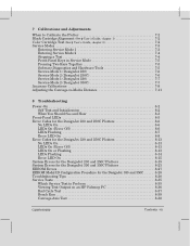
...Cartridge Test (See ' User's Guide, chapter 3 7Ć2 Service Modes 7Ć3 Entering Service Mode 1 7Ć3 Entering Service Mode 2 7Ć4 Stopping a Test 7Ć4 FrontĆPanel Keys in Service Mode 7Ć5 Pressing Two Keys Together 7Ć5 Software Diagnostics and Hardware Tools 7Ć5 ServiceĆMode 1 (DesignJet 230...27 EEROM Model ID Configuration Procedure for the DesignJet 330 and 350C . . . . . 8Ć28 Troubleshooting Tips 8Ć30 Service Tests 8Ć35 Which Service Test to Perform 8Ć35 Viewing Test Output on an HP Palmtop PC 8Ć36 Bail Cycle Test...
...Cartridge Test (See ' User's Guide, chapter 3 7Ć2 Service Modes 7Ć3 Entering Service Mode 1 7Ć3 Entering Service Mode 2 7Ć4 Stopping a Test 7Ć4 FrontĆPanel Keys in Service Mode 7Ć5 Pressing Two Keys Together 7Ć5 Software Diagnostics and Hardware Tools 7Ć5 ServiceĆMode 1 (DesignJet 230...27 EEROM Model ID Configuration Procedure for the DesignJet 330 and 350C . . . . . 8Ć28 Troubleshooting Tips 8Ć30 Service Tests 8Ć35 Which Service Test to Perform 8Ć35 Viewing Test Output on an HP Palmtop PC 8Ć36 Bail Cycle Test...
Service Manual
Page 21
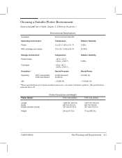
Choosing a Suitable Plotter Environment (Instructions ' User's Guide, chapter 1, w Position the plotter.) Hardware: Operating environment: Plotter With cartridges and media: Environmental Specifications Environmental Class B2 Temperature 0 to 55_C (32 to 131_F) 15 to 35_C (59 to 95_F)... Relative Humidity 5-25% 20-80% Storage environment: Temperature Relative Humidity Plotter/media -40 to +70_C (-40 to +158_F) 5-95% Cartridges -40 to +40_C (-40 to +104_F) Acoustics:* Sound Pressure Sound Power Operating D/A1-size plotters E/A0-size plotters 43 dB (Acoustic) 45 dB (A)...
Choosing a Suitable Plotter Environment (Instructions ' User's Guide, chapter 1, w Position the plotter.) Hardware: Operating environment: Plotter With cartridges and media: Environmental Specifications Environmental Class B2 Temperature 0 to 55_C (32 to 131_F) 15 to 35_C (59 to 95_F)... Relative Humidity 5-25% 20-80% Storage environment: Temperature Relative Humidity Plotter/media -40 to +70_C (-40 to +158_F) 5-95% Cartridges -40 to +40_C (-40 to +104_F) Acoustics:* Sound Pressure Sound Power Operating D/A1-size plotters E/A0-size plotters 43 dB (Acoustic) 45 dB (A)...
Service Manual
Page 34
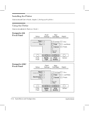
... ' User's Guide, chapter 1, Setting up the plotter.) Using the Plotter (Instructions ' Quick Reference Guide.) DesignJet 230 Front Panel Setup Read Settings Align Cartridges Replot Paper or vellum or translucent Film Cartridge Fast Normal Both ON = Best Error Load Media Ready DesignJet 250C Front Panel Form Feed Media Type Print Quality Cancel Setup Read Settings Align...
... ' User's Guide, chapter 1, Setting up the plotter.) Using the Plotter (Instructions ' Quick Reference Guide.) DesignJet 230 Front Panel Setup Read Settings Align Cartridges Replot Paper or vellum or translucent Film Cartridge Fast Normal Both ON = Best Error Load Media Ready DesignJet 250C Front Panel Form Feed Media Type Print Quality Cancel Setup Read Settings Align...
Service Manual
Page 36
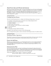
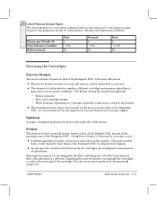
...any are given on the following settings using a setup sheet : D Language of demonstration plot, setup sheet and cartridgeĆalignment sheet D Baud rate and parity of serial interface D Graphics language D Input/output timeout period D ...that the plotter is found to be directly attributed to the use with any of its DesignJet series plotters or printers. PowerĆOn SelfĆTests Whenever you switch the plotter ... pen line widths and shading. ThirdĆParty Inks and OffĆAxis Ink Systems HP does not support thirdĆparty inks or offĆaxis ink systems for use of...
...any are given on the following settings using a setup sheet : D Language of demonstration plot, setup sheet and cartridgeĆalignment sheet D Baud rate and parity of serial interface D Graphics language D Input/output timeout period D ...that the plotter is found to be directly attributed to the use with any of its DesignJet series plotters or printers. PowerĆOn SelfĆTests Whenever you switch the plotter ... pen line widths and shading. ThirdĆParty Inks and OffĆAxis Ink Systems HP does not support thirdĆparty inks or offĆaxis ink systems for use of...
Service Manual
Page 40
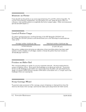
... before using it again. (Other environmental specifications ' chapter 2.) Level of Plotter Usage To achieve good performance and long lifetime of the HP DesignJet 230/250C and HP DesignJet 330/350C plotters, users should use to the bushings if they are made of the carriage, and from the slider rod and chassis... 20 E/A0 CAD plots The service configuration plot gives an indication of how much the plotter has been used: number of plots, number of cartridges, number of capillary action. Oil stays inside them by means of times the plotter has been turned on. (Details ' page 8Ć49/8&#...
... before using it again. (Other environmental specifications ' chapter 2.) Level of Plotter Usage To achieve good performance and long lifetime of the HP DesignJet 230/250C and HP DesignJet 330/350C plotters, users should use to the bushings if they are made of the carriage, and from the slider rod and chassis... 20 E/A0 CAD plots The service configuration plot gives an indication of how much the plotter has been used: number of plots, number of cartridges, number of capillary action. Oil stays inside them by means of times the plotter has been turned on. (Details ' page 8Ć49/8&#...

Service Manual
Page 48
.... 5Ć6 Functional Overview C4699Ć90000 It is guided by two integrated bronze bushings, which are no bail sensor on the DesignJet 230 and 250C and DesignJet 330 and 350C. there are selfĆlubricating, and a back wheel. The strip does not require adjustment. Positional Feedback An ...of the bailĆlift cam and thus improves reliability. BailĆLift Mechanism The bail features an automatic lift mechanism driven by the cartridge carriage. This replaces the dualĆbelt system of the media. D The interface between the motor shaft and belt is also more ...
.... 5Ć6 Functional Overview C4699Ć90000 It is guided by two integrated bronze bushings, which are no bail sensor on the DesignJet 230 and 250C and DesignJet 330 and 350C. there are selfĆlubricating, and a back wheel. The strip does not require adjustment. Positional Feedback An ...of the bailĆlift cam and thus improves reliability. BailĆLift Mechanism The bail features an automatic lift mechanism driven by the cartridge carriage. This replaces the dualĆbelt system of the media. D The interface between the motor shaft and belt is also more ...
Service Manual
Page 49
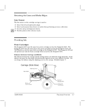
... calibration. As the distance increases, the drop shape and directionality degrade and are more difficult to : D Detect the left and right media edges. The DesignJet 230 and 330 plotters use only the black cartridge which is used in the DesignJet 650C. Detecting the Lines and Media Edges Line Sensor The line sensor on the...
... calibration. As the distance increases, the drop shape and directionality degrade and are more difficult to : D Detect the left and right media edges. The DesignJet 230 and 330 plotters use only the black cartridge which is used in the DesignJet 650C. Detecting the Lines and Media Edges Line Sensor The line sensor on the...
Service Manual
Page 53
... easier to suck ink from becoming clogged. D The absence of the bellows. Installing the incorrect primer can damage the cartridges or reduce the servicing of the DesignJet 650C. (See ' User's Guide, w Cleaning the cartridge nozzles.) D A bellows assembly provides a vacuum to access and remove, and is replaceable as for color plots on paper,... A single, redesigned spittoon is based on that of the DeskJet 1200, instead of the automatic one unit. For the correct part numbers for the DesignJet 230/250C and DesignJet 330/350C look identical, their characteristics are now located on the...
... easier to suck ink from becoming clogged. D The absence of the bellows. Installing the incorrect primer can damage the cartridges or reduce the servicing of the DesignJet 650C. (See ' User's Guide, w Cleaning the cartridge nozzles.) D A bellows assembly provides a vacuum to access and remove, and is replaceable as for color plots on paper,... A single, redesigned spittoon is based on that of the DeskJet 1200, instead of the automatic one unit. For the correct part numbers for the DesignJet 230/250C and DesignJet 330/350C look identical, their characteristics are now located on the...

Service Manual
Page 54
The following diagram gives an overview of the DesignJet 650C. Plotter Architecture The plotters have a multiprocessor architecture similar to that of the architecture: Main Processor (80960CA) Internal Memory (ROM/RAM) Expansion Memory (SIMM DRAM) Upgrade Memory (SIMM ROM) 80960 BUS Swath RAM (1 Mbyte) EEPROM (512 Byte) Support & Shuffler ASIC Servo Processor (8052) Encoders & Motor Drivers Nozzle Timing ASIC IEEE 1284 ASIC Bi-tronics Cartridge Drivers Host RS-232-C Carriage's Line Detector Sensors & Front Panel 5Ć12 Functional Overview C4699Ć90000
The following diagram gives an overview of the DesignJet 650C. Plotter Architecture The plotters have a multiprocessor architecture similar to that of the architecture: Main Processor (80960CA) Internal Memory (ROM/RAM) Expansion Memory (SIMM DRAM) Upgrade Memory (SIMM ROM) 80960 BUS Swath RAM (1 Mbyte) EEPROM (512 Byte) Support & Shuffler ASIC Servo Processor (8052) Encoders & Motor Drivers Nozzle Timing ASIC IEEE 1284 ASIC Bi-tronics Cartridge Drivers Host RS-232-C Carriage's Line Detector Sensors & Front Panel 5Ć12 Functional Overview C4699Ć90000

Service Manual
Page 58
...panel PCA as the DeskJet 550 and DesignJet 220. 5Ć16 Functional Overview C4699Ć90000 The carriage PCA contains: D Optical line sensor D Thermistor circuit D Linear encoder D Cartridge nozzle firing circuit Some electronic components on the DesignJet 250C and 350C carriage PCA are not... present on that of the DesignJet 650C. At powerĆon the plotter firmware identifies whether the carriage is based on the DesignJet 230 and 330 carriage PCA. ...
...panel PCA as the DeskJet 550 and DesignJet 220. 5Ć16 Functional Overview C4699Ć90000 The carriage PCA contains: D Optical line sensor D Thermistor circuit D Linear encoder D Cartridge nozzle firing circuit Some electronic components on the DesignJet 250C and 350C carriage PCA are not... present on that of the DesignJet 650C. At powerĆon the plotter firmware identifies whether the carriage is based on the DesignJet 230 and 330 carriage PCA. ...

Service Manual
Page 63
C4699Ć90000 Removal and Replacement 6Ć5 WARNING In the following step, take care neither to cut yourself on the encoder strip, nor to the extreme left. Removing the Bail 1 Open the top cover. 3 Push one of the plastic ends of the bail towards the center of the plotter to release it from the hole in the sideplate, and lift the bail out of the plotter. 2 Move the cartridge carriage to damage the strip.
C4699Ć90000 Removal and Replacement 6Ć5 WARNING In the following step, take care neither to cut yourself on the encoder strip, nor to the extreme left. Removing the Bail 1 Open the top cover. 3 Push one of the plastic ends of the bail towards the center of the plotter to release it from the hole in the sideplate, and lift the bail out of the plotter. 2 Move the cartridge carriage to damage the strip.
Service Manual
Page 64
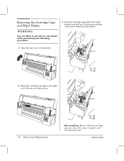
C4699Ć90000 Removing the Cartridge Caps and Wiper Blades WARNING You are likely to get ink on your hands while performing the following procedure. 3 Peel the cartridge caps and/or the wiper blades from the top of the service station, and remove them from the plotter. 1 Open the top cover of the plotter. 2 Move the cartridge carriage to the right, out of the serviceĆstation area. 6Ć6 Removal and Replacement Reassembling: Ensure that the cartridge caps are clean, the wipers straight, and the openings clear.
C4699Ć90000 Removing the Cartridge Caps and Wiper Blades WARNING You are likely to get ink on your hands while performing the following procedure. 3 Peel the cartridge caps and/or the wiper blades from the top of the service station, and remove them from the plotter. 1 Open the top cover of the plotter. 2 Move the cartridge carriage to the right, out of the serviceĆstation area. 6Ć6 Removal and Replacement Reassembling: Ensure that the cartridge caps are clean, the wipers straight, and the openings clear.
Service Manual
Page 72
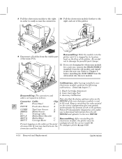
... correct model ID. Be careful not to damage the parallelĆport clamps. 11 If you to the new EEROM. Black Cartridge Alignment 2. To configure plotter ' page 8Ć28. Color Cartridge Test Reassembling: The connectors and 3. Accuracy Calibration cables correspond as follows: Note also that the value printed A on the Connector Cable...
... correct model ID. Be careful not to damage the parallelĆport clamps. 11 If you to the new EEROM. Black Cartridge Alignment 2. To configure plotter ' page 8Ć28. Color Cartridge Test Reassembling: The connectors and 3. Accuracy Calibration cables correspond as follows: Note also that the value printed A on the Connector Cable...

Service Manual
Page 75
C4699Ć90000 Removal and Replacement 6Ć17 Removing the Encoder Strip 1 Move the cartridge carriage to the connector marked P1 on the trailingĆcable guide. 2 Remove the right endĆcover ' page 6Ć10. 3 Remove the left , over the service station. 5 Disconnect the trailing cable from the main PCA. Reassembling: The cable connects to the left endĆcover ' page 6Ć9. 4 Disconnect the trailing cable from the guides on the right bracket 6 Fold the trailing cable upwards and store it on the main PCA.
C4699Ć90000 Removal and Replacement 6Ć17 Removing the Encoder Strip 1 Move the cartridge carriage to the connector marked P1 on the trailingĆcable guide. 2 Remove the right endĆcover ' page 6Ć10. 3 Remove the left , over the service station. 5 Disconnect the trailing cable from the main PCA. Reassembling: The cable connects to the left endĆcover ' page 6Ć9. 4 Disconnect the trailing cable from the guides on the right bracket 6 Fold the trailing cable upwards and store it on the main PCA.

Service Manual
Page 77
... from right to left bracket, and press it right to the base of the carriage assembly. Reinstalling the Encoder Strip 1 Move the cartridge carriage to the left, over the service station. 2 Ensure that the encoder strip is oriented with the transparent area up, and with two holes on ...
... from right to left bracket, and press it right to the base of the carriage assembly. Reinstalling the Encoder Strip 1 Move the cartridge carriage to the left, over the service station. 2 Ensure that the encoder strip is oriented with the transparent area up, and with two holes on ...
Service Manual
Page 86
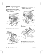
The service station is one orderable assembly. Torx-20 6Ć28 Removal and Replacement Reassembling: Ensure that attaches the service station to the left sideĆplate. C4699Ć90000 Do not open it from the plotter. 3 Remove the screw that the cartridge caps are clean, the wipers straight, and the openings clear. Removing the Service Station 1 Remove the left endĆcover ' page 6Ć9. 2 Disconnect the four short tubes from the primer ink separator. 4 Slide the service station to the left, and remove it .
The service station is one orderable assembly. Torx-20 6Ć28 Removal and Replacement Reassembling: Ensure that attaches the service station to the left sideĆplate. C4699Ć90000 Do not open it from the plotter. 3 Remove the screw that the cartridge caps are clean, the wipers straight, and the openings clear. Removing the Service Station 1 Remove the left endĆcover ' page 6Ć9. 2 Disconnect the four short tubes from the primer ink separator. 4 Slide the service station to the left, and remove it .

Service Manual
Page 92
... the strip. WARNING In the following step, take care neither to 230 250C release two clips at the bottom of the service station. C C D B A 3 Move the carriage out of the cartridge carriage. 6Ć34 Removal and Replacement C4699Ć90000 For DesignJet 230 only, it is also necessary to cut yourself on the top of...
... the strip. WARNING In the following step, take care neither to 230 250C release two clips at the bottom of the service station. C C D B A 3 Move the carriage out of the cartridge carriage. 6Ć34 Removal and Replacement C4699Ć90000 For DesignJet 230 only, it is also necessary to cut yourself on the top of...


