
Service Manual
Page 9
... removal order ...168 Customer self repair (CSR) components 170 Print cartridges ...170 Duplex-reverse guide ...172 Toner-collection unit ...173 Formatter PCA ...175 Memory DIMM ...176 Remove the memory DIMM 176 Enable memory for Windows 177 Tray cassette ...178 Fuser ...179 Pickup roller... (Tray 3 182 Separation roller (Tray 2 183 Secondary transfer roller 184 Reinstall the transfer roller 185 Secondary transfer assembly 186 Reinstall the secondary transfer assembly 187 Intermediate transfer belt (ITB 188 Right door (optional paper feeder 190 External panels, covers, and doors 192 ...
... removal order ...168 Customer self repair (CSR) components 170 Print cartridges ...170 Duplex-reverse guide ...172 Toner-collection unit ...173 Formatter PCA ...175 Memory DIMM ...176 Remove the memory DIMM 176 Enable memory for Windows 177 Tray cassette ...178 Fuser ...179 Pickup roller... (Tray 3 182 Separation roller (Tray 2 183 Secondary transfer roller 184 Reinstall the transfer roller 185 Secondary transfer assembly 186 Reinstall the secondary transfer assembly 187 Intermediate transfer belt (ITB 188 Right door (optional paper feeder 190 External panels, covers, and doors 192 ...

Service Manual
Page 26
... 339 Figure 7-27 Test the optional Tray 3 media-size sensors 339 Figure 7-28 Formatter PCA ...343 Figure 7-29 DC controller PCA ...344 Figure 7-30 Paper feeder driver ...Black print-quality troubleshooting page 362 Figure 7-46 Configuration page ...365 Figure 7-47 HP embedded Jetdirect page ...366 Figure 7-48 Embedded protocol page ...367 Figure 7-49 ... log ...396 Figure 7-50 Jam locations ...405 Figure 8-1 External covers, panels, and doors 454 Figure 8-2 Right door assembly ...456 Figure 8-3 Internal components 1 of 5 ...458 Figure 8-4 Internal components 2 of 5 ...460 Figure 8-5 Internal...
... 339 Figure 7-27 Test the optional Tray 3 media-size sensors 339 Figure 7-28 Formatter PCA ...343 Figure 7-29 DC controller PCA ...344 Figure 7-30 Paper feeder driver ...Black print-quality troubleshooting page 362 Figure 7-46 Configuration page ...365 Figure 7-47 HP embedded Jetdirect page ...366 Figure 7-48 Embedded protocol page ...367 Figure 7-49 ... log ...396 Figure 7-50 Jam locations ...405 Figure 8-1 External covers, panels, and doors 454 Figure 8-2 Right door assembly ...456 Figure 8-3 Internal components 1 of 5 ...458 Figure 8-4 Internal components 2 of 5 ...460 Figure 8-5 Internal...
Service Manual
Page 132
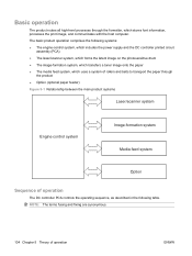
...product routes all high-level processes through the formatter, which uses a system of rollers and belts to transport the paper through the product ● Option (optional paper feeder) Figure 5-1 Relationship between the main product systems Laser/scanner system Engine control system Image-formation ... the following systems: ● The engine-control system, which includes the power supply and the DC controller printed circuit assembly (PCA) ● The laser/scanner system, which forms the latent image on the photosensitive drum ● The image-formation system, which transfers a toner...
...product routes all high-level processes through the formatter, which uses a system of rollers and belts to transport the paper through the product ● Option (optional paper feeder) Figure 5-1 Relationship between the main product systems Laser/scanner system Engine control system Image-formation ... the following systems: ● The engine-control system, which includes the power supply and the DC controller printed circuit assembly (PCA) ● The laser/scanner system, which forms the latent image on the photosensitive drum ● The image-formation system, which transfers a toner...

Service Manual
Page 271
... See Right-rear cover on page 167. NOTE: The formatter cage is only necessary if you are removing the power supply for internal product access, it is removed with the power supply, as an assembly. Remove the low-voltage power supply CAUTION: ESD-sensitive ...part. 1. Disconnect six connectors (callout 1; Low-voltage power supply Before proceeding, remove the following components: ● Formatter. Remove both components as noted in the above ...
... See Right-rear cover on page 167. NOTE: The formatter cage is only necessary if you are removing the power supply for internal product access, it is removed with the power supply, as an assembly. Remove the low-voltage power supply CAUTION: ESD-sensitive ...part. 1. Disconnect six connectors (callout 1; Low-voltage power supply Before proceeding, remove the following components: ● Formatter. Remove both components as noted in the above ...

Service Manual
Page 274
Figure 6-132 Remove the low-voltage power supply (7 of 8) 7. Figure 6-131 Remove the low-voltage power supply (6 of 8) 246 Chapter 6 Removal and replacement ENWW 6. Rotate the formatter cage away from the top of the product. Remove the assembly.
Figure 6-132 Remove the low-voltage power supply (7 of 8) 7. Figure 6-131 Remove the low-voltage power supply (6 of 8) 246 Chapter 6 Removal and replacement ENWW 6. Rotate the formatter cage away from the top of the product. Remove the assembly.

Service Manual
Page 275
NOTE: If you are removing the power supply for internal product access, you can leave the formatter cage installed on the power supply chassis. Figure 6-133 Remove the low-voltage power supply (8 of 8) 7 ENWW Internal assemblies 247 Remove four screws (callout 7), and then separate the formatter cage from the low-voltage power supply. 8.
NOTE: If you are removing the power supply for internal product access, you can leave the formatter cage installed on the power supply chassis. Figure 6-133 Remove the low-voltage power supply (8 of 8) 7 ENWW Internal assemblies 247 Remove four screws (callout 7), and then separate the formatter cage from the low-voltage power supply. 8.

Service Manual
Page 279
...cover. Remove two screws (callout 1). Remove the developing-disengagement motor 1. Developing-disengagement motor Before proceeding, remove the following components: ● Formatter. See Right-rear cover on page 238. See High-voltage power supply lower (HVPS-D) on page 209. See Rear cover and upper-... on page 243. ● High-voltage power supply lower. Figure 6-139 Remove the developing-disengagement motor (1 of 2) 1 ENWW Internal assemblies 251 TIP: For internal product access, you can remove the ICB and the low-voltage power supply as a single component. ● ...
...cover. Remove two screws (callout 1). Remove the developing-disengagement motor 1. Developing-disengagement motor Before proceeding, remove the following components: ● Formatter. See Right-rear cover on page 238. See High-voltage power supply lower (HVPS-D) on page 209. See Rear cover and upper-... on page 243. ● High-voltage power supply lower. Figure 6-139 Remove the developing-disengagement motor (1 of 2) 1 ENWW Internal assemblies 251 TIP: For internal product access, you can remove the ICB and the low-voltage power supply as a single component. ● ...

Service Manual
Page 281
...Low-voltage power supply on page 200. ● Rear cover and upper-rear cover. Figure 6-141 Remove the pickup motor 1 2 ENWW Internal assemblies 253 TIP: For internal product access, you can remove the ICB and the low-voltage power supply as a single component. ● Low-voltage...● Interconnect board (ICB). Remove the pickup motor Disconnect one connector (callout 1), remove two screws (callout 2), and then remove the motor. See Formatter PCA on page 198. ● Left cover. See Right-rear cover on page 175. ● Right-rear cover. Pickup motor Before proceeding, remove ...
...Low-voltage power supply on page 200. ● Rear cover and upper-rear cover. Figure 6-141 Remove the pickup motor 1 2 ENWW Internal assemblies 253 TIP: For internal product access, you can remove the ICB and the low-voltage power supply as a single component. ● Low-voltage...● Interconnect board (ICB). Remove the pickup motor Disconnect one connector (callout 1), remove two screws (callout 2), and then remove the motor. See Formatter PCA on page 198. ● Left cover. See Right-rear cover on page 175. ● Right-rear cover. Pickup motor Before proceeding, remove ...

Service Manual
Page 282
... power supply. Disconnect three connectors (callout 1), and then release the wire harness from the rear cover to remove the lifter drive assembly. ● Interconnect board (ICB). See Low-voltage power supply on page 200. ● Rear cover and upper-rear cover. Remove the lifter...-drive assembly 1. Figure 6-142 Remove the lifter-drive assembly (1 of 2) 1 254 Chapter 6 Removal and replacement ENWW See Formatter PCA on page 238. See Interconnect board (ICB) on page 175. ● Right-rear cover...
... power supply. Disconnect three connectors (callout 1), and then release the wire harness from the rear cover to remove the lifter drive assembly. ● Interconnect board (ICB). See Low-voltage power supply on page 200. ● Rear cover and upper-rear cover. Remove the lifter...-drive assembly 1. Figure 6-142 Remove the lifter-drive assembly (1 of 2) 1 254 Chapter 6 Removal and replacement ENWW See Formatter PCA on page 238. See Interconnect board (ICB) on page 175. ● Right-rear cover...

Service Manual
Page 284
... remove the pickup motor only, see Pickup motor on page 175. ● Right-rear cover. Cassette-pickup drive assembly Before proceeding, remove the following components: ● Formatter. TIP: For internal product access, you can remove the ICB and the low-voltage power supply as a single ...; Low-voltage power supply. Figure 6-144 Remove the cassette-pickup drive assembly (1 of 10) 2 1 256 Chapter 6 Removal and replacement ENWW Remove one screw (callout 1), and then remove the sheet-metal bracket (callout 2). See Formatter PCA on page 253. 1. See Left cover on page 248. See...
... remove the pickup motor only, see Pickup motor on page 175. ● Right-rear cover. Cassette-pickup drive assembly Before proceeding, remove the following components: ● Formatter. TIP: For internal product access, you can remove the ICB and the low-voltage power supply as a single ...; Low-voltage power supply. Figure 6-144 Remove the cassette-pickup drive assembly (1 of 10) 2 1 256 Chapter 6 Removal and replacement ENWW Remove one screw (callout 1), and then remove the sheet-metal bracket (callout 2). See Formatter PCA on page 253. 1. See Left cover on page 248. See...

Service Manual
Page 291
... cover. Remove the cassette-pickup assembly 1. See Registration assembly on page 256. Figure 6-157 Remove the cassette-pickup assembly (1 of 3) 2 1 ENWW Internal assemblies 263 SeeCassette-pickup drive assembly on page 233. ● Interconnect board (ICB). See Rear cover and upper-rear cover on page 175. ● Right-rear cover. See Formatter PCA on page 209. See...
... cover. Remove the cassette-pickup assembly 1. See Registration assembly on page 256. Figure 6-157 Remove the cassette-pickup assembly (1 of 3) 2 1 ENWW Internal assemblies 263 SeeCassette-pickup drive assembly on page 233. ● Interconnect board (ICB). See Rear cover and upper-rear cover on page 175. ● Right-rear cover. See Formatter PCA on page 209. See...

Service Manual
Page 293
... power supply lower. Figure 6-160 Remove the laser/scanner assembly (Y/M) (1 of 12) 2 1 ENWW Internal assemblies 265 See Low-voltage power supply on page 175. ● Right-rear cover. See Toner-collection unit on page 209. See Rear cover and upper-rear cover on page 173. ● Formatter. Remove five screws (callout 1), and then remove...
... power supply lower. Figure 6-160 Remove the laser/scanner assembly (Y/M) (1 of 12) 2 1 ENWW Internal assemblies 265 See Low-voltage power supply on page 175. ● Right-rear cover. See Toner-collection unit on page 209. See Rear cover and upper-rear cover on page 173. ● Formatter. Remove five screws (callout 1), and then remove...

Service Manual
Page 300
... ● Left cover. See Lifter-drive assembly on page 238. See Interconnect board (ICB) on page 254. ● Laser/scanner assembly (Y/M). See Left cover on page 209. ...the rear cover to remove the laser/scanner assembly (C/Bk). ● Interconnect board (ICB). See Laser/scanner assembly (Y/M) on page 248. ● Lifter drive assembly. TIP: For internal product access...power supply lower (HVPS-D) on page 265. 272 Chapter 6 Removal and replacement ENWW Laser/scanner assembly (C/Bk) Before proceeding, remove the following components: ● Toner collection unit. See ...
... ● Left cover. See Lifter-drive assembly on page 238. See Interconnect board (ICB) on page 254. ● Laser/scanner assembly (Y/M). See Left cover on page 209. ...the rear cover to remove the laser/scanner assembly (C/Bk). ● Interconnect board (ICB). See Laser/scanner assembly (Y/M) on page 248. ● Lifter drive assembly. TIP: For internal product access...power supply lower (HVPS-D) on page 265. 272 Chapter 6 Removal and replacement ENWW Laser/scanner assembly (C/Bk) Before proceeding, remove the following components: ● Toner collection unit. See ...

Service Manual
Page 307
See DC controller PCA and tray on page 175. ● Right-rear cover. See Formatter PCA on page 240. ● Low-voltage power supply. NOTE: It is not necessary to separate the upper-rear cover from the rear cover to ... the sheet-metal tray was removed with the DC controller, begin at step 3. 1. Figure 6-184 Remove the high-voltage power supply upper (1 of 5) 1 ENWW Internal assemblies 279 See Low-voltage power supply on page 198. ● Left cover. See Right-rear cover on page 243. TIP: For internal product access, you...
See DC controller PCA and tray on page 175. ● Right-rear cover. See Formatter PCA on page 240. ● Low-voltage power supply. NOTE: It is not necessary to separate the upper-rear cover from the rear cover to ... the sheet-metal tray was removed with the DC controller, begin at step 3. 1. Figure 6-184 Remove the high-voltage power supply upper (1 of 5) 1 ENWW Internal assemblies 279 See Low-voltage power supply on page 198. ● Left cover. See Right-rear cover on page 243. TIP: For internal product access, you...

Service Manual
Page 313
.... See Right-rear cover on page 200. ● Rear cover and upper-rear cover. See Left cover on page 198. ● Left cover. See Formatter PCA on page 243. ● High-voltage power supply upper. See Low-voltage power supply on page 175. ● Right-rear cover. See High-voltage... power supply upper (HVPS-T) on page 238. See Interconnect board (ICB) on page 279. ENWW Internal assemblies 285 See DC controller PCA and tray on page 209. See Rear cover and upper-rear cover on page 240. ● Low-voltage power supply...
.... See Right-rear cover on page 200. ● Rear cover and upper-rear cover. See Left cover on page 198. ● Left cover. See Formatter PCA on page 243. ● High-voltage power supply upper. See Low-voltage power supply on page 175. ● Right-rear cover. See High-voltage... power supply upper (HVPS-T) on page 238. See Interconnect board (ICB) on page 279. ENWW Internal assemblies 285 See DC controller PCA and tray on page 209. See Rear cover and upper-rear cover on page 240. ● Low-voltage power supply...
Service Manual
Page 315
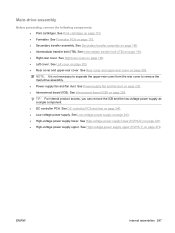
... (ITB). See High-voltage power supply lower (HVPS-D) on page 175. ● Secondary transfer assembly. Main-drive assembly Before proceeding, remove the following components: ● Print cartridges. See Formatter PCA on page 248. ● High-voltage power supply upper. NOTE: It is not necessary to... separate the upper-rear cover from the rear cover to remove the main-drive assembly. ● Power-supply fan and fan...
... (ITB). See High-voltage power supply lower (HVPS-D) on page 175. ● Secondary transfer assembly. Main-drive assembly Before proceeding, remove the following components: ● Print cartridges. See Formatter PCA on page 248. ● High-voltage power supply upper. NOTE: It is not necessary to... separate the upper-rear cover from the rear cover to remove the main-drive assembly. ● Power-supply fan and fan...
Service Manual
Page 326
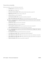
...page 248. ● High-voltage power supply upper. See Control-panel assembly on page 198. ● Left cover. See Right-rear cover on page 203 ● Rear cover and upper-rear cover. See Formatter PCA on page 209. See Rear cover and upper-rear cover on... power supply. See DC controller PCA and tray on page 179. ● Secondary transfer assembly. See Interconnect board (ICB) on page 279. ● Main-drive assembly. Fuser-drive assembly Before proceeding, remove the following components: ● Formatter. See High-voltage power supply upper (HVPS-T) on page 238.
...page 248. ● High-voltage power supply upper. See Control-panel assembly on page 198. ● Left cover. See Right-rear cover on page 203 ● Rear cover and upper-rear cover. See Formatter PCA on page 209. See Rear cover and upper-rear cover on... power supply. See DC controller PCA and tray on page 179. ● Secondary transfer assembly. See Interconnect board (ICB) on page 279. ● Main-drive assembly. Fuser-drive assembly Before proceeding, remove the following components: ● Formatter. See High-voltage power supply upper (HVPS-T) on page 238.

Service Manual
Page 405
...265. 52.20 ERROR To continue turn off then on the test results, perform one of the DC error. See Laser/scanner assembly (C/Bk) on page 272 or Laser/scanner assembly (Y/M) on page 240. To continue turn the product on The environment sensor has experienced an 1. Depending on 53.... and tray on page 265. 52.XY ERROR A printer error has occurred. X=1 slot toward the outside of the formatter board. Turn the product off, and then turn off then on . 2. Replace the cyan/black laser scanner or the yellow/magenta laser-scanner. If this message persists, replace the DC controller...
...265. 52.20 ERROR To continue turn off then on the test results, perform one of the DC error. See Laser/scanner assembly (C/Bk) on page 272 or Laser/scanner assembly (Y/M) on page 240. To continue turn the product on The environment sensor has experienced an 1. Depending on 53.... and tray on page 265. 52.XY ERROR A printer error has occurred. X=1 slot toward the outside of the formatter board. Turn the product off, and then turn off then on . 2. Replace the cyan/black laser scanner or the yellow/magenta laser-scanner. If this message persists, replace the DC controller...
Service Manual
Page 476
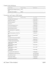
... interfaces Product name Product number HP Jetdirect 635n IPv6/Ipsec print server J7961G (EIO) USB cable 2 meter standard C6518A Customer self repair (CSR) parts Product name Product number 1x500 paper feeder right door kit Duplex reverse guide kit Formatter assembly kit Front door kit Fuser ...(fixing) cleaning kit (8.5x11) Fuser (fixing) 110V service kit Fuser (fixing) 220V service kit HP postcard media insert replacement ITB kit Pick/feed and separation roller ...
... interfaces Product name Product number HP Jetdirect 635n IPv6/Ipsec print server J7961G (EIO) USB cable 2 meter standard C6518A Customer self repair (CSR) parts Product name Product number 1x500 paper feeder right door kit Duplex reverse guide kit Formatter assembly kit Front door kit Fuser ...(fixing) cleaning kit (8.5x11) Fuser (fixing) 110V service kit Fuser (fixing) 220V service kit HP postcard media insert replacement ITB kit Pick/feed and separation roller ...

Service Manual
Page 528
... CC468-67920 Front door kit CC519-67901 CC519-67902 CE859-69001 RC2-3983-000CN Fuser (fixing) 110 V assembly kit Fuser (fixing) 220 V assembly kit Formatter assembly Lever, cartridge pressure front RC2-4406-000CN Shutter front arm RC2-4407-000CN Shutter rear arm 500 Chapter 8 Parts and ...components (2 of 5) on page 461 Internal components (5 of 5) on page 467 External covers, panels, and doors; on page 455 Fusing assembly on page 483 Fusing assembly on page 483 PCAs on page 485 Internal components (1 of 5) on page 459 Internal components (2 of 5) on page 461 Internal components ...
... CC468-67920 Front door kit CC519-67901 CC519-67902 CE859-69001 RC2-3983-000CN Fuser (fixing) 110 V assembly kit Fuser (fixing) 220 V assembly kit Formatter assembly Lever, cartridge pressure front RC2-4406-000CN Shutter front arm RC2-4407-000CN Shutter rear arm 500 Chapter 8 Parts and ...components (2 of 5) on page 461 Internal components (5 of 5) on page 467 External covers, panels, and doors; on page 455 Fusing assembly on page 483 Fusing assembly on page 483 PCAs on page 485 Internal components (1 of 5) on page 459 Internal components (2 of 5) on page 461 Internal components ...


