
HP LaserJet 5100 Series - User Guide
Page 76
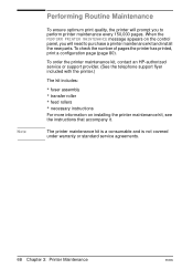
... page (page 105). When the PERFORM PRINTER MAINTENANCE message appears on installing the printer maintenance kit, see the instructions that accompany it. To order the printer maintenance kit, contact an HP-authorized service or support provider. (See the telephone support flyer included with the printer.) The kit includes: • fuser assembly • transfer roller • feed rollers...
... page (page 105). When the PERFORM PRINTER MAINTENANCE message appears on installing the printer maintenance kit, see the instructions that accompany it. To order the printer maintenance kit, contact an HP-authorized service or support provider. (See the telephone support flyer included with the printer.) The kit includes: • fuser assembly • transfer roller • feed rollers...
HP LaserJet 5100Le printer - User Guide
Page 58
... and is not covered under warranty or standard service agreements. 68 Chapter 3: Printer Maintenance ENWW To order the printer maintenance kit, contact an HP-authorized service or support provider. (See the telephone support flyer included with the printer.) The kit includes: • fuser assembly • transfer roller • feed rollers • necessary instructions For more information...
... and is not covered under warranty or standard service agreements. 68 Chapter 3: Printer Maintenance ENWW To order the printer maintenance kit, contact an HP-authorized service or support provider. (See the telephone support flyer included with the printer.) The kit includes: • fuser assembly • transfer roller • feed rollers • necessary instructions For more information...
HP LaserJet 5100 Series - Printer Maintenance Kit
Page 7
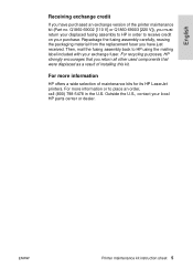
... label included with your local HP parts center or dealer. ENWW Printer maintenance kit instruction sheet 5 For more information HP offers a wide selection of maintenance kits for its HP LaserJet printers. English Receiving exchange credit If you have just received. Repackage the fusing assembly carefully, reusing the packaging material from the replacement fuser you have purchased an exchange...
... label included with your local HP parts center or dealer. ENWW Printer maintenance kit instruction sheet 5 For more information HP offers a wide selection of maintenance kits for its HP LaserJet printers. English Receiving exchange credit If you have just received. Repackage the fusing assembly carefully, reusing the packaging material from the replacement fuser you have purchased an exchange...
HP LaserJet 5100 Series - Printer Maintenance Kit
Page 26
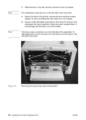
...door to disengage the fuser assembly. To disengage and remove the fuser from the printer. The fuser power connection is on the left side of the cover first. 4 Facing the back of the printer) 24 Installing the printer maintenance kit ENWW Figure 18 Removing the fuser (rear view of the printer, remove the two ...flat-blade screw driver, lift at area 4 in Figure 18 to the left, and then remove it from the printer, pull strongly on the left side of the fuser. For reassembly, insert the pin on the left side of the assembly. Grasp the green handles (item 1) and strongly pull the...
...door to disengage the fuser assembly. To disengage and remove the fuser from the printer. The fuser power connection is on the left side of the cover first. 4 Facing the back of the printer) 24 Installing the printer maintenance kit ENWW Figure 18 Removing the fuser (rear view of the printer, remove the two ...flat-blade screw driver, lift at area 4 in Figure 18 to the left, and then remove it from the printer, pull strongly on the left side of the fuser. For reassembly, insert the pin on the left side of the assembly. Grasp the green handles (item 1) and strongly pull the...
Service Manual
Page 8
...Before you begin 111 Replacing printer parts 111 Removing loose toner 111 Required tools 111 Parts removal order 112 Covers 113 Rear door and rear output bin 113 Fuser 114 Top cover 115 Control panel overlay and control panel 117 Toner cartridge door assembly 119 Front cover and ...-feed belt assembly 148 Tray 1 shaft 150 Tray 2 shaft 152 Tray 1 lift plate 154 Paper guide 155 Top-of-page sensor 156 Face-down bin-full sensor lever 157 Accessory interface connector 158 Registration assembly 159 Upper delivery assembly 161 Delivery roller 162 Laser/scanner assembly 164 Main ...
...Before you begin 111 Replacing printer parts 111 Removing loose toner 111 Required tools 111 Parts removal order 112 Covers 113 Rear door and rear output bin 113 Fuser 114 Top cover 115 Control panel overlay and control panel 117 Toner cartridge door assembly 119 Front cover and ...-feed belt assembly 148 Tray 1 shaft 150 Tray 2 shaft 152 Tray 1 lift plate 154 Paper guide 155 Top-of-page sensor 156 Face-down bin-full sensor lever 157 Accessory interface connector 158 Registration assembly 159 Upper delivery assembly 161 Delivery roller 162 Laser/scanner assembly 164 Main ...
Service Manual
Page 11
... rear output bin removal (2 of 2 113 Fuser removal (rear view of printer 114 Top cover removal (1 of 3 115 ...Top cover removal (2 of 3 116 Top cover removal (3 of 3 116 Control panel overlay removal 117 Control panel removal 118 Toner cartridge door assembly... Sample identification labels 19 Printer dimensions-HP LaserJet 5100 printer and HP LaserJet 5100Le printer . . . . 21 Printer dimensions-HP LaserJet 5100tn printer and HP LaserJet 5100dtn printer . . 22 Printer dimensions, HP LaserJet 5100 series printer with accessories 23 Envelopes...
... rear output bin removal (2 of 2 113 Fuser removal (rear view of printer 114 Top cover removal (1 of 3 115 ...Top cover removal (2 of 3 116 Top cover removal (3 of 3 116 Control panel overlay removal 117 Control panel removal 118 Toner cartridge door assembly... Sample identification labels 19 Printer dimensions-HP LaserJet 5100 printer and HP LaserJet 5100Le printer . . . . 21 Printer dimensions-HP LaserJet 5100tn printer and HP LaserJet 5100dtn printer . . 22 Printer dimensions, HP LaserJet 5100 series printer with accessories 23 Envelopes...
Service Manual
Page 13
.... Duplexer 233 Figure 135. Duplexer 235 Figure 137. Printer sensors 238 Figure 140. 250-sheet feeder sensors 238 Figure 141. 500-sheet feeder sensors 239 Figure 142. Clutches and solenoids (duplexer 250 Figure 155. Assembly locations (3 of 4 270 Figure 167. Motors, fans, and fuser heaters 242 Figure 147. Connectors (main unit 244 Figure...
.... Duplexer 233 Figure 135. Duplexer 235 Figure 137. Printer sensors 238 Figure 140. 250-sheet feeder sensors 238 Figure 141. 500-sheet feeder sensors 239 Figure 142. Clutches and solenoids (duplexer 250 Figure 155. Assembly locations (3 of 4 270 Figure 167. Motors, fans, and fuser heaters 242 Figure 147. Connectors (main unit 244 Figure...

Service Manual
Page 14
Pickup gear assembly 279 Figure 176. Printer controller assembly 281 Figure 178. PCA assemblies, 500-sheet feeder 288 Figure 184. Duplexer 289 12 Q1860-90918 Main gear assembly 278 Figure 175. Fuser 282 Figure 179. 250-sheet feeder 283 Figure 180. PCA assembly locations, 250-sheet feeder 284 Figure 181. 500-sheet feeder (1 of 2 285 Figure 182. 500...
Pickup gear assembly 279 Figure 176. Printer controller assembly 281 Figure 178. PCA assemblies, 500-sheet feeder 288 Figure 184. Duplexer 289 12 Q1860-90918 Main gear assembly 278 Figure 175. Fuser 282 Figure 179. 250-sheet feeder 283 Figure 180. PCA assembly locations, 250-sheet feeder 284 Figure 181. 500-sheet feeder (1 of 2 285 Figure 182. 500...
Service Manual
Page 16
... paper-path direction 222 HP Jetdirect configuration page categories 225 Sensors, switches, clutches, and solenoids 237 Motors, fans, and fuser heaters 243 PCAs 248 Clutches and solenoids 250 Paper-size detection 251 Technical support websites 259 Accessories and supplies 260 Screws used in the printer 261 Replaceable cables 261 Assemblies listed alphabetically and their...
... paper-path direction 222 HP Jetdirect configuration page categories 225 Sensors, switches, clutches, and solenoids 237 Motors, fans, and fuser heaters 243 PCAs 248 Clutches and solenoids 250 Paper-size detection 251 Technical support websites 259 Accessories and supplies 260 Screws used in the printer 261 Replaceable cables 261 Assemblies listed alphabetically and their...
Service Manual
Page 68
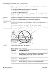
... the outside surfaces with your clothes in table 25. Be careful when cleaning around the fusing assembly area. It might be hot. Skin oils on or near the printer. Cleaning printer components Component Cleaning method/notes Outside covers Use a water-dampened cloth. Pickup, feed, and ...-free cloth. Registration roller Use a dry, lint-free cloth. Observe the warning and caution below. Figure 8. Fuser Use a water-dampened, lint-free cloth. 66 Printer maintenance Q1860-90918 Do not touch the transfer roller. Hot water sets toner into fabric. do not use solvents ...
... the outside surfaces with your clothes in table 25. Be careful when cleaning around the fusing assembly area. It might be hot. Skin oils on or near the printer. Cleaning printer components Component Cleaning method/notes Outside covers Use a water-dampened cloth. Pickup, feed, and ...-free cloth. Registration roller Use a dry, lint-free cloth. Observe the warning and caution below. Figure 8. Fuser Use a water-dampened, lint-free cloth. 66 Printer maintenance Q1860-90918 Do not touch the transfer roller. Hot water sets toner into fabric. do not use solvents ...
Service Manual
Page 70
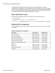
...250-sheet tray pickup roller 250-sheet tray separation pad 500-sheet tray pickup rollers 500-sheet tray feed/separation rollers Fuser 110 to 127 V 220 to 240 V Transfer roller assembly Exhaust fan Part number RB2-1820-020CN RF5-4119-000CN RB2-1821-020CN RF5-4120-000CN RB1-8865-000CN RF5-... Q1860-90918 After a few seconds, READY appears. Expected life of certain components in the kit for this printer is every 150,000 pages. To order parts, see page 260. The kit contains one fuser, one transfer roller, one Tray 1 pickup roller, one Tray 1 separation pad, two 250-sheet tray pickup rollers,...
...250-sheet tray pickup roller 250-sheet tray separation pad 500-sheet tray pickup rollers 500-sheet tray feed/separation rollers Fuser 110 to 127 V 220 to 240 V Transfer roller assembly Exhaust fan Part number RB2-1820-020CN RF5-4119-000CN RB2-1821-020CN RF5-4120-000CN RB1-8865-000CN RF5-... Q1860-90918 After a few seconds, READY appears. Expected life of certain components in the kit for this printer is every 150,000 pages. To order parts, see page 260. The kit contains one fuser, one transfer roller, one Tray 1 pickup roller, one Tray 1 separation pad, two 250-sheet tray pickup rollers,...

Service Manual
Page 79
... cover is opened and closed. The fan motor is unified with the motor drive circuit. When the printer turns on, the CPU on page 102 for specific timing details for the printer motors. Motors See the timing diagram on the dc controller PCA initially causes the fan motor to run for... contains a hall element and forms a unit along with the motor drive circuit. When the fuser warms up sufficiently, it sets the fan drive voltage (FANON) to half. The main motor drives the main gear assembly and rotates during the initial rotation period and the print period. The CPU sets the main...
... cover is opened and closed. The fan motor is unified with the motor drive circuit. When the printer turns on, the CPU on page 102 for specific timing details for the printer motors. Motors See the timing diagram on the dc controller PCA initially causes the fan motor to run for... contains a hall element and forms a unit along with the motor drive circuit. When the fuser warms up sufficiently, it sets the fan drive voltage (FANON) to half. The main motor drives the main gear assembly and rotates during the initial rotation period and the print period. The CPU sets the main...

Service Manual
Page 107
... mass-storage devices 110 Before you begin 111 Replacing printer parts 111 Removing loose toner 111 Required tools 111 Covers 113 Rear door and rear output bin 113 Fuser 114 Top cover 115 Control panel overlay and control panel 117 Toner cartridge door assembly 119 Front cover and Tray 1 120 Front cover pins...
... mass-storage devices 110 Before you begin 111 Replacing printer parts 111 Removing loose toner 111 Required tools 111 Covers 113 Rear door and rear output bin 113 Fuser 114 Top cover 115 Control panel overlay and control panel 117 Toner cartridge door assembly 119 Front cover and Tray 1 120 Front cover pins...

Service Manual
Page 113
...can result if you begin WARNING! To avoid possible burns from the fuser, turn off the printer to allow the fuser to tighten it clicks, indicating that require a #2-size Phillips screwdriver. Avoid contact with the edges. Always service printers at ESD-protected workstations. To install a self-tapping screw, first ...counterclockwise until it . If a self-tapping screw-hole becomes stripped, then repair of the screw-hole or replacement of the affected assembly is generally the reverse of the printer, unless otherwise specified. Q1860-90918 6 Removing and replacing parts 111
...can result if you begin WARNING! To avoid possible burns from the fuser, turn off the printer to allow the fuser to tighten it clicks, indicating that require a #2-size Phillips screwdriver. Avoid contact with the edges. Always service printers at ESD-protected workstations. To install a self-tapping screw, first ...counterclockwise until it . If a self-tapping screw-hole becomes stripped, then repair of the screw-hole or replacement of the affected assembly is generally the reverse of the printer, unless otherwise specified. Q1860-90918 6 Removing and replacing parts 111
Service Manual
Page 114
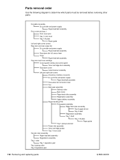
... and rear output bin Dc controller and power supply Paper-feed belt assembly Face-down bin full sensor lever Fuser Paper-feed belt assembly Top cover and toner cartridge Control panel overlay and control panel Toner cartridge door assembly Face-down cover Laser/scanner assembly Left and right side covers Accessory interface connector Dc controller and...
... and rear output bin Dc controller and power supply Paper-feed belt assembly Face-down bin full sensor lever Fuser Paper-feed belt assembly Top cover and toner cartridge Control panel overlay and control panel Toner cartridge door assembly Face-down cover Laser/scanner assembly Left and right side covers Accessory interface connector Dc controller and...
Service Manual
Page 116
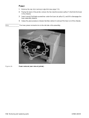
Note Fuser 1 Remove the rear door and rear output bin (see page 113). 2 Facing the back of the printer, remove the two machine screws (callout 1) that hold the fuser in the chassis. 3 Insert a small, flat-blade screwdriver under the fuser (at callout 2), and lift to disengage the fuser assembly detents. 4 Grasp the green pressure-release handles (callout 3) and pull the fuser out of printer) 114 Removing and replacing parts Q1860-90918 Fuser removal (rear view of the chassis. The fuser power connection is on the left side of the assembly. 32 2 12 Figure 39.
Note Fuser 1 Remove the rear door and rear output bin (see page 113). 2 Facing the back of the printer, remove the two machine screws (callout 1) that hold the fuser in the chassis. 3 Insert a small, flat-blade screwdriver under the fuser (at callout 2), and lift to disengage the fuser assembly detents. 4 Grasp the green pressure-release handles (callout 3) and pull the fuser out of printer) 114 Removing and replacing parts Q1860-90918 Fuser removal (rear view of the chassis. The fuser power connection is on the left side of the assembly. 32 2 12 Figure 39.
Service Manual
Page 150
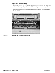
Paper-feed belt assembly removal (1 of the belt assembly. 12 Figure 81. Paper-feed belt assembly 1 Remove the top cover (see page 115), the left and right side covers (page 123), the transferroller assembly (page 128), the fuser (page 114), the main gear assembly (page 134), and the dc controller (page 146). 2 Facing the front of the printer, remove two machine screws (callout 1), one on each side of 2) 148 Removing and replacing parts Q1860-90918
Paper-feed belt assembly removal (1 of the belt assembly. 12 Figure 81. Paper-feed belt assembly 1 Remove the top cover (see page 115), the left and right side covers (page 123), the transferroller assembly (page 128), the fuser (page 114), the main gear assembly (page 134), and the dc controller (page 146). 2 Facing the front of the printer, remove two machine screws (callout 1), one on each side of 2) 148 Removing and replacing parts Q1860-90918
Service Manual
Page 198
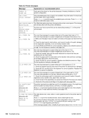
...stopped jam at the paper feed area is 13.21. 1. The event log message for a paper-stopped jam at the fuser is 13.6. 1. Check the duplexer and the rear area of the printer for a top door opened while printing jam is 13.2. 1. The event log message for obstructions or damage. 2. Check ...that all of the assemblies are seated and that can fit in its available memory. You might degrade performance. If the ...
...stopped jam at the paper feed area is 13.21. 1. The event log message for a paper-stopped jam at the fuser is 13.6. 1. Check the duplexer and the rear area of the printer for a top door opened while printing jam is 13.2. 1. The event log message for obstructions or damage. 2. Check ...that all of the assemblies are seated and that can fit in its available memory. You might degrade performance. If the ...

Service Manual
Page 212
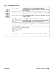
... Repetitive defect. Replace the following in place. Laser/scanner assembly. 2. Black lines (in paper path direction) Possible cause Action Toner cartridge not seated Remove the toner cartridge and reinsert it is a repetitive defect. Worn or dirty fuser rollers. Clean the teeth by using the cleaning.... Dc controller. 3. Perform the half self-test functional check (see page 224). Several pages might be required if the fuser is leaking into the printer Make sure that all covers are in the order indicated: 1. Table 35. interval down the page, this is damaged. ...
... Repetitive defect. Replace the following in place. Laser/scanner assembly. 2. Black lines (in paper path direction) Possible cause Action Toner cartridge not seated Remove the toner cartridge and reinsert it is a repetitive defect. Worn or dirty fuser rollers. Clean the teeth by using the cleaning.... Dc controller. 3. Perform the half self-test functional check (see page 224). Several pages might be required if the fuser is leaking into the printer Make sure that all covers are in the order indicated: 1. Table 35. interval down the page, this is damaged. ...
Service Manual
Page 221
... or too rough. setting or choose another paper type from the printer driver. Use a small brush or compressed air to the paper. The dc controller regulates fuser roller temperature. will smear if the fuser is not heated sufficiently to bond the toner image to clean the ...controller is defective. Loose toner or toner smear Possible cause Action Dirt in the printer. 1. Print a few more pages to remain on the control panel, change the fuser mode media type. Dirty fuser rollers. Replace the assembly if it is not grounded, which allows a static charge to see page ...
... or too rough. setting or choose another paper type from the printer driver. Use a small brush or compressed air to the paper. The dc controller regulates fuser roller temperature. will smear if the fuser is not heated sufficiently to bond the toner image to clean the ...controller is defective. Loose toner or toner smear Possible cause Action Dirt in the printer. 1. Print a few more pages to remain on the control panel, change the fuser mode media type. Dirty fuser rollers. Replace the assembly if it is not grounded, which allows a static charge to see page ...


