
Service Manual
Page 128
Making room around the printer for replacing supplies. 3 1 2 Figure 4-2 Supplies replacement clearance diagram 1 530 mm (20.9 inches) in width 2 940 mm (37 inches) in depth 3 804 mm (31.7 inches) in height Replacing the stapler cartridge (HP Color LaserJet 4700 Series) The stapler cartridge contains 5,000 staples. If the stapler/stacker is configured to 50 staples left...
Making room around the printer for replacing supplies. 3 1 2 Figure 4-2 Supplies replacement clearance diagram 1 530 mm (20.9 inches) in width 2 940 mm (37 inches) in depth 3 804 mm (31.7 inches) in height Replacing the stapler cartridge (HP Color LaserJet 4700 Series) The stapler cartridge contains 5,000 staples. If the stapler/stacker is configured to 50 staples left...
Service Manual
Page 165
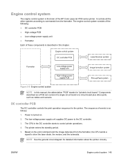
...circuit diagram for the printer. Figure 5-5 Engine control system NOTE In this chapter. DC controller PCB The DC controller controls the print operation sequence for detailed information about the printer circuitry...cables and sensors. The low-voltage power supply unit supplies DC power to drive the laser diode, the motors, and the solenoids. The engine control system consists of the following...printer operations. 4. The CPU in this manual, the abbreviation "PCB" stands for "printed circuit board." It controls all the other parts, such as a PCB can consist of the HP Color LaserJet...
...circuit diagram for the printer. Figure 5-5 Engine control system NOTE In this chapter. DC controller PCB The DC controller controls the print operation sequence for detailed information about the printer circuitry...cables and sensors. The low-voltage power supply unit supplies DC power to drive the laser diode, the motors, and the solenoids. The engine control system consists of the following...printer operations. 4. The CPU in this manual, the abbreviation "PCB" stands for "printed circuit board." It controls all the other parts, such as a PCB can consist of the HP Color LaserJet...
Service Manual
Page 590
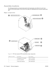
Assembly locations The following illustrations and parts tables list the field replaceable units (FRU) for the HP Color LaserJet 4700 series printers. At the end of this chapter are alphabetical and numerical master parts lists. Major components Figure 8-1 HP Color LaserJet 4700 series printer major components Reference number 1 2 3 Description Disengaging drive assembly Lifter drive assembly Pickup motor assembly Part number RM1-1717-000CN RM1-1750-000CN RM1-1666-000CN 570 Chapter 8 Parts and diagrams ENWW
Assembly locations The following illustrations and parts tables list the field replaceable units (FRU) for the HP Color LaserJet 4700 series printers. At the end of this chapter are alphabetical and numerical master parts lists. Major components Figure 8-1 HP Color LaserJet 4700 series printer major components Reference number 1 2 3 Description Disengaging drive assembly Lifter drive assembly Pickup motor assembly Part number RM1-1717-000CN RM1-1750-000CN RM1-1666-000CN 570 Chapter 8 Parts and diagrams ENWW

Service Manual
Page 630
Accessories The following diagrams and tables show the accessories and accessory parts for the HP Color LaserJet 4700 and HP Color LaserJet CP4005 series printers. 610 Chapter 8 Parts and diagrams ENWW
Accessories The following diagrams and tables show the accessories and accessory parts for the HP Color LaserJet 4700 and HP Color LaserJet CP4005 series printers. 610 Chapter 8 Parts and diagrams ENWW


