
Service Manual
Page 9
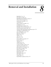
... Station Assembly 8-8 Drop Detector Assembly 8-10 Vacuum Fan 8-11 Paper-axis Motor Assembly 8-12 Left Hand Cover 8-13 Left Hand Trim Assembly 8-18 Ink Supply Station Assembly (ISS) 8-19 Air Pressurization System (APS) 8-20 Clutch Assembly and left hand miscellaneous parts 8-21 Tail Deflectors and Rear Platen 8-23 Left and Right Rear Covers 8-24 HP DesignJets 1050C and 1055CM Printers Service...
... Station Assembly 8-8 Drop Detector Assembly 8-10 Vacuum Fan 8-11 Paper-axis Motor Assembly 8-12 Left Hand Cover 8-13 Left Hand Trim Assembly 8-18 Ink Supply Station Assembly (ISS) 8-19 Air Pressurization System (APS) 8-20 Clutch Assembly and left hand miscellaneous parts 8-21 Tail Deflectors and Rear Platen 8-23 Left and Right Rear Covers 8-24 HP DesignJets 1050C and 1055CM Printers Service...

Service Manual
Page 10
... Platen Assembly 8-62 Platen Assembly 8-63 Paper Entry Assembly 8-64 Roller Guide 8-66 Media Holder Strip 8-69 Drive Roller 8-70 Center Guide 8-71 Pinch-Wheel Assembly and Cam 8-73 Preventive Maintenance 9-1 Moisture on the Printer 9-2 Noisy Carriage Bushing 9-2 Belt Swelling 9-2 Cleaning the Printer 9-2 General Cleaning 9-2 Cleaning the Overdrive 9-3 Scheduled Maintenance 9-3 Level of Printer Usage 9-3 Scan-axis Maintenance 9-4 8 HP DesignJets 1050C...
... Platen Assembly 8-62 Platen Assembly 8-63 Paper Entry Assembly 8-64 Roller Guide 8-66 Media Holder Strip 8-69 Drive Roller 8-70 Center Guide 8-71 Pinch-Wheel Assembly and Cam 8-73 Preventive Maintenance 9-1 Moisture on the Printer 9-2 Noisy Carriage Bushing 9-2 Belt Swelling 9-2 Cleaning the Printer 9-2 General Cleaning 9-2 Cleaning the Overdrive 9-3 Scheduled Maintenance 9-3 Level of Printer Usage 9-3 Scan-axis Maintenance 9-4 8 HP DesignJets 1050C...

Service Manual
Page 91
...Printheads and the Tubes System installed ... Press Enter HP DesignJets 1050C and 1055CM Printers Service Manual...Tubes System is replaced. IF THIS TEST PASSES, DO NOT REPLACE THE SCAN AXIS MOTOR. Scan Axis The purpose of the Printer.... IF THE CARRIAGE IS MOVING IT WILL NOT STOP IF THE WINDOW IS OPENED, SO BE VERY CAREFUL NOT TO PUT YOUR HANDS INSIDE. Service Tests and Utilities WARNING WARNING NOTE NOTE 5. You must perform the Scan-Axis Test after: n Scan-Axis Assemblies... are disassembled or replaced. n Carriage is important that once you MUST power OFF the Printer...
...Printheads and the Tubes System installed ... Press Enter HP DesignJets 1050C and 1055CM Printers Service Manual...Tubes System is replaced. IF THIS TEST PASSES, DO NOT REPLACE THE SCAN AXIS MOTOR. Scan Axis The purpose of the Printer.... IF THE CARRIAGE IS MOVING IT WILL NOT STOP IF THE WINDOW IS OPENED, SO BE VERY CAREFUL NOT TO PUT YOUR HANDS INSIDE. Service Tests and Utilities WARNING WARNING NOTE NOTE 5. You must perform the Scan-Axis Test after: n Scan-Axis Assemblies... are disassembled or replaced. n Carriage is important that once you MUST power OFF the Printer...
Service Manual
Page 209
... Motor Assembly 8-33 Encoder Strip 8-34 Tensioner 8-37 Trailing Cable 8-39 Cutter Assembly 8-42 Carriage Assembly and Belt 8-44 Tubes System Assembly 8-53 Ink Leak Detector Assembly 8-60 Front Platen Assembly 8-62 Platen Assembly 8-63 Paper Entry Assembly 8-64 Roller Guide 8-66 Media Holder Strip 8-69 Drive Roller 8-70 Center Guide 8-71 Pinch-Wheel Assembly and Cam 8-73 HP DesignJets 1050C and 1055CM Printers Service...
... Motor Assembly 8-33 Encoder Strip 8-34 Tensioner 8-37 Trailing Cable 8-39 Cutter Assembly 8-42 Carriage Assembly and Belt 8-44 Tubes System Assembly 8-53 Ink Leak Detector Assembly 8-60 Front Platen Assembly 8-62 Platen Assembly 8-63 Paper Entry Assembly 8-64 Roller Guide 8-66 Media Holder Strip 8-69 Drive Roller 8-70 Center Guide 8-71 Pinch-Wheel Assembly and Cam 8-73 HP DesignJets 1050C and 1055CM Printers Service...

Service Manual
Page 222
This will release the complete assembly. 1 8-14 2 Figure 10: Latches HP DesignJets 1050C and 1055CM Printers Service Manual Removal and Installation 2. Release the tube holder (item 1) from the rear of the ink cartridge tube connector outwards (refer to Figure 9). 1 2082a Figure 9: Tube Grip 3. Twist the two latches at the rear of the left hand cover by pushing it up and out (refer to Figure 10).
This will release the complete assembly. 1 8-14 2 Figure 10: Latches HP DesignJets 1050C and 1055CM Printers Service Manual Removal and Installation 2. Release the tube holder (item 1) from the rear of the ink cartridge tube connector outwards (refer to Figure 9). 1 2082a Figure 9: Tube Grip 3. Twist the two latches at the rear of the left hand cover by pushing it up and out (refer to Figure 10).

Service Manual
Page 223
Disconnect the ink cartridge tube connector cable (refer to Figure 11). 1 2082c Figure 11: Ink Cartridge Tube Connector (pulled back) 5. Slide the ink cartridge tube connector assembly towards you (refer to Figure 12). 1 Figure 12: Ink Cartridge Tube Connector Cable HP DesignJets 1050C and 1055CM Printers Service Manual 8-15 Removal and Installation 4.
Disconnect the ink cartridge tube connector cable (refer to Figure 11). 1 2082c Figure 11: Ink Cartridge Tube Connector (pulled back) 5. Slide the ink cartridge tube connector assembly towards you (refer to Figure 12). 1 Figure 12: Ink Cartridge Tube Connector Cable HP DesignJets 1050C and 1055CM Printers Service Manual 8-15 Removal and Installation 4.
Service Manual
Page 228
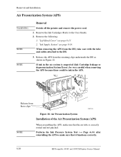
... System Test (⇒ Page 4-14) after reinstalling the APS to make sure that it functions correctly. 8-20 HP DesignJets 1050C and 1055CM Printers Service Manual Remove the Ink Cartridges (Refer to the ISS. 3. When removing the APS from the retaining clips underneath the ISS as shown ... these clips C607443 Figure 18: Air Pressurization System Installation of the Air Pressurization System (APS) NOTE When assembling the APS, make sure that the air tube is suspected (Ink Cartridge leakage or depressurization System Error), be very careful when removing the APS because there could be...
... System Test (⇒ Page 4-14) after reinstalling the APS to make sure that it functions correctly. 8-20 HP DesignJets 1050C and 1055CM Printers Service Manual Remove the Ink Cartridges (Refer to the ISS. 3. When removing the APS from the retaining clips underneath the ISS as shown ... these clips C607443 Figure 18: Air Pressurization System Installation of the Air Pressurization System (APS) NOTE When assembling the APS, make sure that the air tube is suspected (Ink Cartridge leakage or depressurization System Error), be very careful when removing the APS because there could be...
Service Manual
Page 261
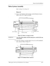
... (Refer to Figure 63. Ink cartridges Printer carriage Printhead Cleaners (inside cover) WARNING Figure 52: Printer Carriage Location Now turn off the printer with the main power switch at the rear of the printer. 2. Removal and Installation Tubes System Assembly Refer to Figure 52 to Figure 53). 1 Figure 53: Printhead Tube Connector HP DesignJets 1050C and 1055CM Printers Service Manual 8-53 Removal...
... (Refer to Figure 63. Ink cartridges Printer carriage Printhead Cleaners (inside cover) WARNING Figure 52: Printer Carriage Location Now turn off the printer with the main power switch at the rear of the printer. 2. Removal and Installation Tubes System Assembly Refer to Figure 52 to Figure 53). 1 Figure 53: Printhead Tube Connector HP DesignJets 1050C and 1055CM Printers Service Manual 8-53 Removal...

Service Manual
Page 264
This will release the complete assembly (refer to the outwards. Removal and Installation 9. Twist the two latches (item 1) at the rear of the ink cartridge tube connector (item 2) to Figure 58). 1 2 2082a Figure 58: Latches 10. Slide the ink cartridge tube connector assembly (item 1) towards you (refer to Figure 59). 1 2082c Figure 59: Ink Cartridge Tube Connector (pulled back) 8-56 HP DesignJets 1050C and 1055CM Printers Service Manual
This will release the complete assembly (refer to the outwards. Removal and Installation 9. Twist the two latches (item 1) at the rear of the ink cartridge tube connector (item 2) to Figure 58). 1 2 2082a Figure 58: Latches 10. Slide the ink cartridge tube connector assembly (item 1) towards you (refer to Figure 59). 1 2082c Figure 59: Ink Cartridge Tube Connector (pulled back) 8-56 HP DesignJets 1050C and 1055CM Printers Service Manual

Service Manual
Page 266
Removal and Installation 13. Push the tab (item 1) towards you and then push the complete tube retaining clip (item 2) to the right and then pull towards you (refer to Figure 62). 2 1 C607431 Figure 62: Ink Cartridge Tube Connector (pulled out) 14. Remove the ink cartridge tube connector (item 1) from the rear of the left hand cover (item 2), rest the assembly on the left hand cover (refer to Figure 63) 2 1 8-58 Figure 63: Tube Retaining Clip HP DesignJets 1050C and 1055CM Printers Service Manual
Removal and Installation 13. Push the tab (item 1) towards you and then push the complete tube retaining clip (item 2) to the right and then pull towards you (refer to Figure 62). 2 1 C607431 Figure 62: Ink Cartridge Tube Connector (pulled out) 14. Remove the ink cartridge tube connector (item 1) from the rear of the left hand cover (item 2), rest the assembly on the left hand cover (refer to Figure 63) 2 1 8-58 Figure 63: Tube Retaining Clip HP DesignJets 1050C and 1055CM Printers Service Manual

Service Manual
Page 292
...the structure of the Tubes System assembly are : n Support the tubes in good condition until it inappropriate for the tube carrier. These ribs are a pair of friction. n Conduct the air from wear and to be protected. The Tube guides are made from the Ink Cartridge to fatigue ...stress limitations, the space between the tubes and the guides is delivered to the tubes. 10-6 HP DesignJets 1050C and 1055CM Printers Service Manual Due to the Printhead. It is to avoid...
...the structure of the Tubes System assembly are : n Support the tubes in good condition until it inappropriate for the tube carrier. These ribs are a pair of friction. n Conduct the air from wear and to be protected. The Tube guides are made from the Ink Cartridge to fatigue ...stress limitations, the space between the tubes and the guides is delivered to the tubes. 10-6 HP DesignJets 1050C and 1055CM Printers Service Manual Due to the Printhead. It is to avoid...
Service Manual
Page 293
... valve and sensor in an off-axis ink supply, called Ink Level Sensing (ILS). The air circuit includes the Ink Cartridges, flexible air tubing, manifold connectors for the highest possible flow rate. The printer controls the pressure of ink left in one chassis which also doubles ... of the transformer is a function of HP DesignJets 1050C and 1055CM Printers Service Manual 10-7 Connection is a service replaceable module that only a minimum pressure needs to each other so that provides and controls the pressurization of this assembly clips under the ISS Housing. The APS...
... valve and sensor in an off-axis ink supply, called Ink Level Sensing (ILS). The air circuit includes the Ink Cartridges, flexible air tubing, manifold connectors for the highest possible flow rate. The printer controls the pressure of ink left in one chassis which also doubles ... of the transformer is a function of HP DesignJets 1050C and 1055CM Printers Service Manual 10-7 Connection is a service replaceable module that only a minimum pressure needs to each other so that provides and controls the pressurization of this assembly clips under the ISS Housing. The APS...
Service Manual
Page 316
... 10-4 Tubes System 10-6 Functional Specifications 10-12 H Hard Disk Drive Service Test 4-12 HP DesignJet Online 10-23 HP No.80 Supplies 3-2 General Information 3-4 HP No.80 Supplies 3-5 replacing 3-6 solving problems 3-17 Hue shift 1-12 I Ink Cartridge Status...Ink Supply Station 8-19, 10-5 Installing Air Pressurization System 8-20 Carriage Assembly 8-51 Electronics Module 8-27 Platen Assembly 8-63 Right Hand Cover 8-6 Trailing Cable 8-40 Interface Specifications 10-17 ISS Assembly 7-14 L Leak Detect System 10-8 Left Hand Cover 7-10, 8-13 Left Hand Trim 8-18 Left Rear Cover 8-24 Level of Printer...
... 10-4 Tubes System 10-6 Functional Specifications 10-12 H Hard Disk Drive Service Test 4-12 HP DesignJet Online 10-23 HP No.80 Supplies 3-2 General Information 3-4 HP No.80 Supplies 3-5 replacing 3-6 solving problems 3-17 Hue shift 1-12 I Ink Cartridge Status...Ink Supply Station 8-19, 10-5 Installing Air Pressurization System 8-20 Carriage Assembly 8-51 Electronics Module 8-27 Platen Assembly 8-63 Right Hand Cover 8-6 Trailing Cable 8-40 Interface Specifications 10-17 ISS Assembly 7-14 L Leak Detect System 10-8 Left Hand Cover 7-10, 8-13 Left Hand Trim 8-18 Left Rear Cover 8-24 Level of Printer...
Service Manual
Page 317
... information 3-9 Problems Color Accuracy 6-22 Color Alignment 6-8 Color Consistency 6-22 Color-to-Color Alignment 6-15 Cover Sensors 1-6 Horizontal Lines 6-17 Line Sensor 1-6 Long Term Color Bleeding 6-22 Media-handling 1-14 Printing lines 6-14 Stepped lines 6-13 Vacuum Fan 1-9 Vacuum suction 1-9 R Rear Covers 7-4 Rear Platen 8-23 Regulatory Notices 10-18 Release Info 4-32 HP DesignJets 1050C and 1055CM Printers Service Manual...
... information 3-9 Problems Color Accuracy 6-22 Color Alignment 6-8 Color Consistency 6-22 Color-to-Color Alignment 6-15 Cover Sensors 1-6 Horizontal Lines 6-17 Line Sensor 1-6 Long Term Color Bleeding 6-22 Media-handling 1-14 Printing lines 6-14 Stepped lines 6-13 Vacuum Fan 1-9 Vacuum suction 1-9 R Rear Covers 7-4 Rear Platen 8-23 Regulatory Notices 10-18 Release Info 4-32 HP DesignJets 1050C and 1055CM Printers Service Manual...
Service Manual
Page 318
... 4-32 Index-4 HP DesignJets 1050C and 1055CM Printers Service Manual Index Removing Air Pressurization System 8-20 Back Cover 8-32 Belt 8-44 Carriage Assembly 8-44 Center Guide 8-71 Clutch Assembly 8-21 Cutter Assembly 8-42 Drive Roller 8-70 Drop Detector Assembly 8-10 Electronics Module 8-25 Encoder Strip 8-34 Front Panel Assembly 8-6 Front Platen Assembly 8-62 Ink Leak Detector Assembly 8-60 Ink Supply Station Assembly 8-19 Left...
... 4-32 Index-4 HP DesignJets 1050C and 1055CM Printers Service Manual Index Removing Air Pressurization System 8-20 Back Cover 8-32 Belt 8-44 Carriage Assembly 8-44 Center Guide 8-71 Clutch Assembly 8-21 Cutter Assembly 8-42 Drive Roller 8-70 Drop Detector Assembly 8-10 Electronics Module 8-25 Encoder Strip 8-34 Front Panel Assembly 8-6 Front Platen Assembly 8-62 Ink Leak Detector Assembly 8-60 Ink Supply Station Assembly 8-19 Left...


