Manual
Page 1
MW70-3S0 Dual LGA2011 sockets R3 motherboard for Intel® E5-2600 V3 series processors User's Manual Rev. 1001
MW70-3S0 Dual LGA2011 sockets R3 motherboard for Intel® E5-2600 V3 series processors User's Manual Rev. 1001
Manual
Page 3
Table of Contents Box Contents...5 MW70-3S0 Motherboard Layout 6 Block Diagram...9 Chapter 1 Hardware Installation 10 1-1 Installation Precautions 10 1-2 Product Specifications 11 1-3 Installing the CPU and CPU Cooler 13 1-3-1 Installing the CPU...13 1-3-2 Installing the CPU Cooler 16 1-4 Installing the Memory 17 1-4-1 Four Channel Memory Configuration 17 1-4-2 Installing a Memory 18 1-4-3 DIMM Population Table 18 1-5 Back Panel Connectors 19 1-6 Internal Connectors 21 1-7 Jumper Settings 38 - 3 -
Table of Contents Box Contents...5 MW70-3S0 Motherboard Layout 6 Block Diagram...9 Chapter 1 Hardware Installation 10 1-1 Installation Precautions 10 1-2 Product Specifications 11 1-3 Installing the CPU and CPU Cooler 13 1-3-1 Installing the CPU...13 1-3-2 Installing the CPU Cooler 16 1-4 Installing the Memory 17 1-4-1 Four Channel Memory Configuration 17 1-4-2 Installing a Memory 18 1-4-3 DIMM Population Table 18 1-5 Back Panel Connectors 19 1-6 Internal Connectors 21 1-7 Jumper Settings 38 - 3 -
Manual
Page 5
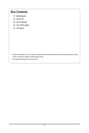
The box contents are for reference only. - 5 - Box Contents Motherboard Driver CD User's Manual Two SATA cables I/O Shield • The box contents above are subject to change without notice. • The motherboard image is for reference only and the actual items shall depend on the product package you obtain.
The box contents are for reference only. - 5 - Box Contents Motherboard Driver CD User's Manual Two SATA cables I/O Shield • The box contents above are subject to change without notice. • The motherboard image is for reference only and the actual items shall depend on the product package you obtain.
Manual
Page 6
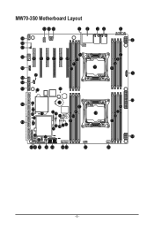
MW70-3S0 Motherboard Layout 63 64 65 12 34 5 59 58 57 70 56 60 62 66 67 68 69 71 72 55 73 11 61 54 53 52 51 74 6 7 8 9 10 12 50 48U 75 22 47 46 45 44 31 32 76 23 24 19 49 43 25 29 28 27 26 30 42 37 38 41 40 39 36 35 34 33 21 13 14 15 16 17 18 20 - 6 -
MW70-3S0 Motherboard Layout 63 64 65 12 34 5 59 58 57 70 56 60 62 66 67 68 69 71 72 55 73 11 61 54 53 52 51 74 6 7 8 9 10 12 50 48U 75 22 47 46 45 44 31 32 76 23 24 19 49 43 25 29 28 27 26 30 42 37 38 41 40 39 36 35 34 33 21 13 14 15 16 17 18 20 - 6 -
Manual
Page 8
... connector Serial port cable header S/PDIF in order to reduce any risk of hard disk damage. If a SATA type hard drive is connected to the motherboard, please ensure the jumper is closed and set to Page 39 for secondary CPU) BMC firmware readiness LED Battery socket Buzzer CAUTION!
... connector Serial port cable header S/PDIF in order to reduce any risk of hard disk damage. If a SATA type hard drive is connected to the motherboard, please ensure the jumper is closed and set to Page 39 for secondary CPU) BMC firmware readiness LED Battery socket Buzzer CAUTION!
Manual
Page 10
... product, please verify that all cables and power connectors of your hardware components are connected. • To prevent damage to the motherboard, do not have an ESD wrist strap, keep your hands dry and first touch a metal object to eliminate static electricity. ...electronic components such as a result of the product, please consult a certified computer technician. Chapter 1 Hardware Installation 1-1 Installation Precautions The motherboard contains numerous delicate electronic circuits and components which can lead to damage to system components as well as physical harm to the user....
... product, please verify that all cables and power connectors of your hardware components are connected. • To prevent damage to the motherboard, do not have an ESD wrist strap, keep your hands dry and first touch a metal object to eliminate static electricity. ...electronic components such as a result of the product, please consult a certified computer technician. Chapter 1 Hardware Installation 1-1 Installation Precautions The motherboard contains numerous delicate electronic circuits and components which can lead to damage to system components as well as physical harm to the user....
Manual
Page 13
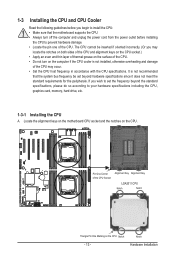
...to your hardware specifications including the CPU, graphics card, memory, hard drive, etc. 1-3-1 Installing the CPU A. Locate the alignment keys on the motherboard CPU socket and the notches on the CPU Notch - 13 - Notch Hardware Installation The CPU cannot be inserted if oriented incorrectly. (Or you begin... to install the CPU: • Make sure that the motherboard supports the CPU. • Always turn on the computer if the CPU cooler is not recommended that the system bus frequency be set the ...
...to your hardware specifications including the CPU, graphics card, memory, hard drive, etc. 1-3-1 Installing the CPU A. Locate the alignment keys on the motherboard CPU socket and the notches on the CPU Notch - 13 - Notch Hardware Installation The CPU cannot be inserted if oriented incorrectly. (Or you begin... to install the CPU: • Make sure that the motherboard supports the CPU. • Always turn on the computer if the CPU cooler is not recommended that the system bus frequency be set the ...

Manual
Page 14
... the socket contacts after the load plate is opened.) Step 4: Hold the CPU with the socket alignment keys) and carefully insert the CPU into the motherboard CPU socket. •• Before installing the CPU, make sure to turn off the computer and unplug the power cord from the socket to rise...
... the socket contacts after the load plate is opened.) Step 4: Hold the CPU with the socket alignment keys) and carefully insert the CPU into the motherboard CPU socket. •• Before installing the CPU, make sure to turn off the computer and unplug the power cord from the socket to rise...
Manual
Page 16
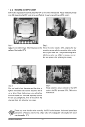
... CPU cooler.) Step 1: Step 2: Apply an even and thin layer of the CPU cooler to the CPU fan header (CPU_FAN) on the motherboard. (Actual installation process may adhere to hold the cooler and the other pair. Please pay more attention when removing the CPU cooler because the ... used. Next, fully tighten the four screws. 1-3-2 Installing the CPU Cooler Refer to the steps below to correctly install the CPU cooler on the motherboard. Step 4: Finally, attach the power connector of thermal grease on the ILM. (If your cooler has a fan grill which may damage the CPU...
... CPU cooler.) Step 1: Step 2: Apply an even and thin layer of the CPU cooler to the CPU fan header (CPU_FAN) on the motherboard. (Actual installation process may adhere to hold the cooler and the other pair. Please pay more attention when removing the CPU cooler because the ... used. Next, fully tighten the four screws. 1-3-2 Installing the CPU Cooler Refer to the steps below to correctly install the CPU cooler on the motherboard. Step 4: Finally, attach the power connector of thermal grease on the ILM. (If your cooler has a fan grill which may damage the CPU...
Manual
Page 17
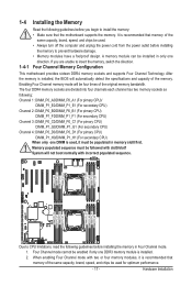
Four Channel Memory Configuration This motherboard provides sixteen DDR4 memory sockets and supports Four Channel Technology. Hardware Installation 1-4 Installing the Memory 1-4-1 Read the following guidelines before installing the memory to prevent ... enabling Four Channel mode with incorrect populated sequence. Memory populated sequence must be four times of the memory. After the memory is recommended that the motherboard supports the memory. Enabling Four Channel memory mode will automatically detect the specifications and capacity of the original memory bandwidth.
Four Channel Memory Configuration This motherboard provides sixteen DDR4 memory sockets and supports Four Channel Technology. Hardware Installation 1-4 Installing the Memory 1-4-1 Read the following guidelines before installing the memory to prevent ... enabling Four Channel mode with incorrect populated sequence. Memory populated sequence must be four times of the memory. After the memory is recommended that the motherboard supports the memory. Enabling Four Channel memory mode will automatically detect the specifications and capacity of the original memory bandwidth.

Manual
Page 18
Step 2. Reverse the installation steps when you wish to install DDR4 DIMMs on this motherboard. Installation Step: Step 1. Insert the DIMM memory module vertically into the DIMM slot, and push it down. Step 3. Be sure to remove the DIMM module. 1 2 2 1-4-3 ...
Step 2. Reverse the installation steps when you wish to install DDR4 DIMMs on this motherboard. Installation Step: Step 1. Insert the DIMM memory module vertically into the DIMM slot, and push it down. Step 3. Be sure to remove the DIMM module. 1 2 2 1-4-3 ...

Manual
Page 20
... data rate • When removing the cable connected to a back panel connector, first remove the cable from your device and then remove it from the motherboard. • When removing the cable, pull it side to side to prevent an electrical short inside the cable connector. Do not rock it straight out...
... data rate • When removing the cable connected to a back panel connector, first remove the cable from your device and then remove it from the motherboard. • When removing the cable, pull it side to side to prevent an electrical short inside the cable connector. Do not rock it straight out...

Manual
Page 22
Hardware Installation - 22 - Unplug the power cord from the power outlet to prevent damage to the devices. • After installing the device and before connecting external devices: • First make sure the device cable has been securely attached to turn off the devices and your devices are compliant with the connectors you wish to connect. • Before installing the devices, be sure to the connector on the computer, make sure your computer. Read the following guidelines before turning on the motherboard.
Hardware Installation - 22 - Unplug the power cord from the power outlet to prevent damage to the devices. • After installing the device and before connecting external devices: • First make sure the device cable has been securely attached to turn off the devices and your devices are compliant with the connectors you wish to connect. • Before installing the devices, be sure to the connector on the computer, make sure your computer. Read the following guidelines before turning on the motherboard.

Manual
Page 23
... supply cable to the CPU. Before connecting the power connector, first make sure the power supply is turned off and all the components on the motherboard. If the 12V power connector is not connected, the computer will not start. • To meet expansion requirements, it is used (500W or greater). The...
... supply cable to the CPU. Before connecting the power connector, first make sure the power supply is turned off and all the components on the motherboard. If the 12V power connector is not connected, the computer will not start. • To meet expansion requirements, it is used (500W or greater). The...
Manual
Page 24
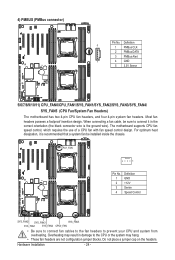
... be installed inside the chassis. Most fan headers possess a foolproof insertion design. Overheating may hang. • These fan headers are not configuration jumper blocks. The motherboard supports CPU fan speed control, which requires the use of a CPU fan with fan speed control design. Definition 5 1 PMBus CLK 2 PMBus DATA 3 PMBus ...Alert 1 4 GND 5 3.3V Sense 5/6/7/8/9/10/11) CPU_FAN0/CPU_FAN1/SYS_FAN1/SYS_FAN2/SYS_FAN3/SYS_FAN4/ SYS_FAN5 (CPU Fan/System Fan Headers) The motherboard has two 4-pin CPU fan headers, and four 4-pin system fan headers.
... be installed inside the chassis. Most fan headers possess a foolproof insertion design. Overheating may hang. • These fan headers are not configuration jumper blocks. The motherboard supports CPU fan speed control, which requires the use of a CPU fan with fan speed control design. Definition 5 1 PMBus CLK 2 PMBus DATA 3 PMBus ...Alert 1 4 GND 5 3.3V Sense 5/6/7/8/9/10/11) CPU_FAN0/CPU_FAN1/SYS_FAN1/SYS_FAN2/SYS_FAN3/SYS_FAN4/ SYS_FAN5 (CPU Fan/System Fan Headers) The motherboard has two 4-pin CPU fan headers, and four 4-pin system fan headers.

Manual
Page 33
Incorrect connection between the module connector and the motherboard header will make the device unable to this header. You may connect your chassis provides an AC'97 front panel audio module. 29) F_VGA (Front ... supports Intel High Definition audio (HD) and AC'97 audio. Make sure the wire assignments of the module connector match the pin assignments of the motherboard header.
Incorrect connection between the module connector and the motherboard header will make the device unable to this header. You may connect your chassis provides an AC'97 front panel audio module. 29) F_VGA (Front ... supports Intel High Definition audio (HD) and AC'97 audio. Make sure the wire assignments of the module connector match the pin assignments of the motherboard header.

Manual
Page 39
...may cause damage to clear the CMOS values (e.g. Definition 1 P5V 1 2 SATA1 Pin7 3 GND 3) CLR_CMOS (Clearing CMOS Jumper) Use this jumper to the motherboard. - 39 - To clear the CMOS values, place a jumper cap on the two pins to temporarily short the two pins or use a metal object like... defaults. Hardware Installation 1/2) SATA_DOM0/SATA_DOM0 (SATA port 0 and port 1 DOM Jumpers) CAUTION! • If the SATA DOM power is supplied by the motherboard, set the jumper to pin 1-2. • If the SATA DOM power is supplied by external power, set the jumper to pin 2-3. • If ...
...may cause damage to clear the CMOS values (e.g. Definition 1 P5V 1 2 SATA1 Pin7 3 GND 3) CLR_CMOS (Clearing CMOS Jumper) Use this jumper to the motherboard. - 39 - To clear the CMOS values, place a jumper cap on the two pins to temporarily short the two pins or use a metal object like... defaults. Hardware Installation 1/2) SATA_DOM0/SATA_DOM0 (SATA port 0 and port 1 DOM Jumpers) CAUTION! • If the SATA DOM power is supplied by the motherboard, set the jumper to pin 1-2. • If the SATA DOM power is supplied by external power, set the jumper to pin 2-3. • If ...


