Manual
Page 3
Table of Contents Box Contents...5 MW70-3S0 Motherboard Layout 6 Block Diagram...9 Chapter 1 Hardware Installation 10 1-1 Installation Precautions 10 1-2 Product Specifications 11 1-3 Installing the CPU and CPU Cooler 13 1-3-1 Installing the CPU...13 1-3-2 Installing the CPU Cooler 16 1-4 Installing the Memory 17 1-4-1 Four Channel Memory Configuration 17 1-4-2 Installing a Memory 18 1-4-3 DIMM Population Table 18 1-5 Back Panel Connectors 19 1-6 Internal Connectors 21 1-7 Jumper Settings 38 - 3 -
Table of Contents Box Contents...5 MW70-3S0 Motherboard Layout 6 Block Diagram...9 Chapter 1 Hardware Installation 10 1-1 Installation Precautions 10 1-2 Product Specifications 11 1-3 Installing the CPU and CPU Cooler 13 1-3-1 Installing the CPU...13 1-3-2 Installing the CPU Cooler 16 1-4 Installing the Memory 17 1-4-1 Four Channel Memory Configuration 17 1-4-2 Installing a Memory 18 1-4-3 DIMM Population Table 18 1-5 Back Panel Connectors 19 1-6 Internal Connectors 21 1-7 Jumper Settings 38 - 3 -

Manual
Page 7
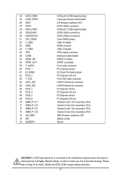
... CPU) System fan connector#5 CPU0 fan connector (for Primary CPU) Channel 4 slot 1 (for primary CPU) Channel 4 slot 0 (for primary CPU) Channel 3 slot 1 (for primary CPU) Channel 3 slot 0 (for primary CPU) ME update jumper Force to Stop FRB Timer jumper ME recovry jumper Clearing Supervisor Password jumper BIOS recovery jumper LSI UART header Intel Software RAID Key jumper System fan connector#4 System fan connector#3 Mini-SAS HD connector SATA SGPIO header LSI RAID key header sSATA SGPIO header Front panel header System fan connector#1 HDD back plane board header System fan connector#2 SATA...
... CPU) System fan connector#5 CPU0 fan connector (for Primary CPU) Channel 4 slot 1 (for primary CPU) Channel 4 slot 0 (for primary CPU) Channel 3 slot 1 (for primary CPU) Channel 3 slot 0 (for primary CPU) ME update jumper Force to Stop FRB Timer jumper ME recovry jumper Clearing Supervisor Password jumper BIOS recovery jumper LSI UART header Intel Software RAID Key jumper System fan connector#4 System fan connector#3 Mini-SAS HD connector SATA SGPIO header LSI RAID key header sSATA SGPIO header Front panel header System fan connector#1 HDD back plane board header System fan connector#2 SATA...
Manual
Page 8
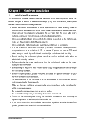
... any risk of hard disk damage. If a SATA type hard drive is connected to the motherboard, please ensure the jumper is closed and set to 2-3 pins (Default setting), in header S/PDIF out header Front audio connector PCI Express x8 slot S3 Power On Select jumper PCI Express x16 slot Front VGA cable connector LAN #1 Active/Link connector LAN #2 Active/Link connector PCI Express x8 slot PCI Express x16 slot PCI Express x8 slot PCI Express x16 slot Channel 3 slot 1 (for secondary CPU) Channel 3 slot 0 (for secondary CPU) Channel 4 slot 1 (for secondary CPU) Channel 4 slot 0 (for SATA_DOM0 and...
... any risk of hard disk damage. If a SATA type hard drive is connected to the motherboard, please ensure the jumper is closed and set to 2-3 pins (Default setting), in header S/PDIF out header Front audio connector PCI Express x8 slot S3 Power On Select jumper PCI Express x16 slot Front VGA cable connector LAN #1 Active/Link connector LAN #2 Active/Link connector PCI Express x8 slot PCI Express x16 slot PCI Express x8 slot PCI Express x16 slot Channel 3 slot 1 (for secondary CPU) Channel 3 slot 0 (for secondary CPU) Channel 4 slot 1 (for secondary CPU) Channel 4 slot 0 (for SATA_DOM0 and...
Manual
Page 10
... or within the computer casing. • Do not place the computer system on an uneven surface. • Do not place the computer system in a high-temperature environment. • Turning on the motherboard, make sure the power supply voltage has been set according to the local voltage standard. • Before using the product, please verify that all cables and power connectors of your dealer. If...
... or within the computer casing. • Do not place the computer system on an uneven surface. • Do not place the computer system in a high-temperature environment. • Turning on the motherboard, make sure the power supply voltage has been set according to the local voltage standard. • Before using the product, please verify that all cables and power connectors of your dealer. If...
Manual
Page 11
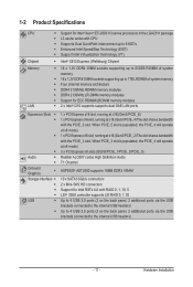
... at x8 mode.) 3 x PCI Express x8 slots (GEN3/PCIE_1/PCIE_3/PCIE_5) Realtek ALC887 codec High Definition Audio 7.1 Channel ASPEED® AST2400 supports 16MB DDR3 VRAM 10 x SATA3 6Gb/s connectors 2 x Mini-SAS HD connectors Support for ECC RDIMM/LRDIMM memory modules ŠŠ 2 x Intel® I210 supports supports dual GbE LAN ports Expansion Slots ŠŠ ŠŠ ŠŠ ŠŠ Audio ŠŠ ŠŠ Onboard Graphics ŠŠ Storage Interface...
... at x8 mode.) 3 x PCI Express x8 slots (GEN3/PCIE_1/PCIE_3/PCIE_5) Realtek ALC887 codec High Definition Audio 7.1 Channel ASPEED® AST2400 supports 16MB DDR3 VRAM 10 x SATA3 6Gb/s connectors 2 x Mini-SAS HD connectors Support for ECC RDIMM/LRDIMM memory modules ŠŠ 2 x Intel® I210 supports supports dual GbE LAN ports Expansion Slots ŠŠ ŠŠ ŠŠ ŠŠ Audio ŠŠ ŠŠ Onboard Graphics ŠŠ Storage Interface...
Manual
Page 12
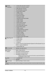
... CPU fan headers ŠŠ 5 x System fan headers ŠŠ 1 x Front panel header ŠŠ 1 x HDD Back plane board header ŠŠ 1 x USB 3.0 header ŠŠ 1 x USB 2.0 header ŠŠ 1 x TPM module connector ŠŠ 1 x Serial port connector ŠŠ 1 x Front VGA cable connector ŠŠ 2 x SATA SPGIO headers ŠŠ 1 x IPMB connector ŠŠ 1 x Software RAID key connector ŠŠ 1 x LSI RAID key connector ŠŠ 1 x S/PDIF in header ŠŠ 1 x S/PDIF out header ŠŠ 2 x LAN LED connectors ŠŠ 1 x Chassis...
... CPU fan headers ŠŠ 5 x System fan headers ŠŠ 1 x Front panel header ŠŠ 1 x HDD Back plane board header ŠŠ 1 x USB 3.0 header ŠŠ 1 x USB 2.0 header ŠŠ 1 x TPM module connector ŠŠ 1 x Serial port connector ŠŠ 1 x Front VGA cable connector ŠŠ 2 x SATA SPGIO headers ŠŠ 1 x IPMB connector ŠŠ 1 x Software RAID key connector ŠŠ 1 x LSI RAID key connector ŠŠ 1 x S/PDIF in header ŠŠ 1 x S/PDIF out header ŠŠ 2 x LAN LED connectors ŠŠ 1 x Chassis...
Manual
Page 13
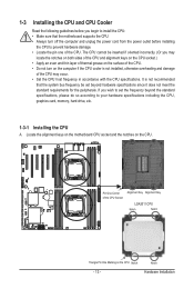
... that the motherboard supports the CPU. • Always turn on the computer if the CPU cooler is not recommended that the system bus frequency be set the frequency beyond hardware specifications since it does not meet the standard requirements for the peripherals. 1-3 Installing the CPU and CPU Cooler Read the following guidelines before installing the CPU to your hardware specifications including the CPU, graphics card, memory, hard drive, etc. 1-3-1 Installing the CPU A. Pin One Corner...
... that the motherboard supports the CPU. • Always turn on the computer if the CPU cooler is not recommended that the system bus frequency be set the frequency beyond hardware specifications since it does not meet the standard requirements for the peripherals. 1-3 Installing the CPU and CPU Cooler Read the following guidelines before installing the CPU to your hardware specifications including the CPU, graphics card, memory, hard drive, etc. 1-3-1 Installing the CPU A. Pin One Corner...

Manual
Page 14
...correctly install the CPU into the motherboard CPU socket. •• Before installing the CPU, make sure to turn off the computer and unplug the power cord from the power outlet to prevent damage to release it if the CPU is removed. ...socket to the CPU. •• To protect the socket contacts, do not remove the protective plastic cover unless the CPU is opened.) Step 4: Hold the CPU with the socket alignment keys) and carefully insert the CPU into the CPU socket. Open the load plate. (Note: DO NOT touch the socket contacts after the load plate is inserted into the socket...
...correctly install the CPU into the motherboard CPU socket. •• Before installing the CPU, make sure to turn off the computer and unplug the power cord from the power outlet to prevent damage to release it if the CPU is removed. ...socket to the CPU. •• To protect the socket contacts, do not remove the protective plastic cover unless the CPU is opened.) Step 4: Hold the CPU with the socket alignment keys) and carefully insert the CPU into the CPU socket. Open the load plate. (Note: DO NOT touch the socket contacts after the load plate is inserted into the socket...
Manual
Page 16
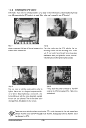
...the motherboard. Then do the same to the other to tighten the screws in a diagonal sequence with the screw diagonally opposite the one you tighten the screws, remove it first and replace it after tightening the screws.) Step 3: Use one hand to the CPU fan header ...removing the CPU cooler may differ depending the CPU cooler to the CPU. Next, fully tighten the four screws. Step 4: Finally, attach the power connector of the installed CPU. Refer to the user's manual for your cooler has a fan grill which may adhere to be used. Please pay more attention when removing the CPU...
...the motherboard. Then do the same to the other to tighten the screws in a diagonal sequence with the screw diagonally opposite the one you tighten the screws, remove it first and replace it after tightening the screws.) Step 3: Use one hand to the CPU fan header ...removing the CPU cooler may differ depending the CPU cooler to the CPU. Next, fully tighten the four screws. Step 4: Finally, attach the power connector of the installed CPU. Refer to the user's manual for your cooler has a fan grill which may adhere to be used. Please pay more attention when removing the CPU...
Manual
Page 17
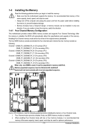
... secondary CPU) Channel 4: DIMM_P0_D0/DIMM_P0_D1 (For pimary CPU) DIMM_P1_H0/DIMM_P1_H1 (For secondary CPU) When only one DIMM is recommended that the motherboard supports the memory. Enabling Four Channel memory mode will automatically detect the specifications and capacity of the same capacity, brand, speed, and chips be used , it is used . • Always turn off the computer and unplug the power cord from the power outlet before installing the memory in memory slot0...
... secondary CPU) Channel 4: DIMM_P0_D0/DIMM_P0_D1 (For pimary CPU) DIMM_P1_H0/DIMM_P1_H1 (For secondary CPU) When only one DIMM is recommended that the motherboard supports the memory. Enabling Four Channel memory mode will automatically detect the specifications and capacity of the same capacity, brand, speed, and chips be used , it is used . • Always turn off the computer and unplug the power cord from the power outlet before installing the memory in memory slot0...

Manual
Page 18
... power outlet to prevent damage to remove the DIMM module. 1 2 2 1-4-3 DIMM Population Table Two Slots Channel RDIMM Population Configuration Within a Channel Type RDIMM Ranks Per DIMM and Data Width Speed (MT/s); Step 3. Reverse the installation steps when you wish to the memory module. Step 2. Close the plastic clip at both edges of the DIMM slots to install DDR4 DIMMs on this motherboard. Slot Per Channel...
... power outlet to prevent damage to remove the DIMM module. 1 2 2 1-4-3 DIMM Population Table Two Slots Channel RDIMM Population Configuration Within a Channel Type RDIMM Ranks Per DIMM and Data Width Speed (MT/s); Step 3. Reverse the installation steps when you wish to the memory module. Step 2. Close the plastic clip at both edges of the DIMM slots to install DDR4 DIMMs on this motherboard. Slot Per Channel...
Manual
Page 19
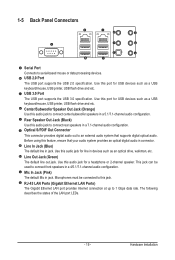
... audio jack for USB devices such as a USB keyboard/mouse, USB printer, USB flash drive and etc. Use this audio jack to connect rear speakers in connector. Use this port for a headphone or 2-channel speaker. Mic In Jack (Pink) The default Mic in jack. Line In Jack (Blue) The default line in jack. Hardware Installation 1-5 Back Panel Connectors Serial Port Connects to 1 Gbps data rate. USB 3.0 Port The USB port supports the USB 3.0 specification. RJ-45 LAN Ports (Gigabit Ethernet LAN Ports) The Gigabit Ethernet LAN port provides Internet connection...
... audio jack for USB devices such as a USB keyboard/mouse, USB printer, USB flash drive and etc. Use this audio jack to connect rear speakers in connector. Use this port for a headphone or 2-channel speaker. Mic In Jack (Pink) The default Mic in jack. Line In Jack (Blue) The default line in jack. Hardware Installation 1-5 Back Panel Connectors Serial Port Connects to 1 Gbps data rate. USB 3.0 Port The USB port supports the USB 3.0 specification. RJ-45 LAN Ports (Gigabit Ethernet LAN Ports) The Gigabit Ethernet LAN port provides Internet connection...

Manual
Page 20
...panel connector, first remove the cable from your device and then remove it from the motherboard. • When removing the cable, pull it straight out from the connector. Hardware Installation - 20 - Speed LED Link Activity LED 10/100/1000 LAN Port Speed LED: State Yellow On Yellow Blink Green On Green Blink Off Link/Activity LED...and network or no access Blinking Data transmission or receiving is occurring Off No data transmission or receiving is occurring rate 10 Mbps data rate • When removing the cable connected to prevent an electrical short inside the cable connector.
...panel connector, first remove the cable from your device and then remove it from the motherboard. • When removing the cable, pull it straight out from the connector. Hardware Installation - 20 - Speed LED Link Activity LED 10/100/1000 LAN Port Speed LED: State Yellow On Yellow Blink Green On Green Blink Off Link/Activity LED...and network or no access Blinking Data transmission or receiving is occurring Off No data transmission or receiving is occurring rate 10 Mbps data rate • When removing the cable connected to prevent an electrical short inside the cable connector.

Manual
Page 23
Before connecting the power connector, first make sure the power supply is turned off and all the components on the motherboard. Connect the power supply cable to the CPU. The 12V power connector mainly supplies power to the power connector in the correct orientation. If the 12V power connector is not connected, the computer will not start. • To meet expansion requirements, it is used that can withstand high power consumption be used (500W or greater). If a power supply is...
Before connecting the power connector, first make sure the power supply is turned off and all the components on the motherboard. Connect the power supply cable to the CPU. The 12V power connector mainly supplies power to the power connector in the correct orientation. If the 12V power connector is not connected, the computer will not start. • To meet expansion requirements, it is used that can withstand high power consumption be used (500W or greater). If a power supply is...
Manual
Page 24
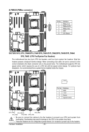
... to connect fan cables to the fan headers to the CPU or the system may result in the correct orientation (the black connector wire is recommended that a system fan be sure to connect it is the ground wire). Do not place a jumper cap on the headers. The motherboard supports CPU fan speed control, which requires the use of a CPU fan with fan speed control design. 4) PMBUS (PMBus connector) Pin No. Overheating may hang. • These fan headers are not configuration jumper...
... to connect fan cables to the fan headers to the CPU or the system may result in the correct orientation (the black connector wire is recommended that a system fan be sure to connect it is the ground wire). Do not place a jumper cap on the headers. The motherboard supports CPU fan speed control, which requires the use of a CPU fan with fan speed control design. 4) PMBUS (PMBus connector) Pin No. Overheating may hang. • These fan headers are not configuration jumper...
Manual
Page 25
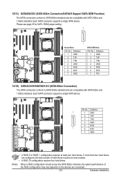
... GND SATA DOM Mode: Pin No. 1 2 3 4 5 6 7 Definition GND TXP TXN GND RXN RXP P5V DEBUG PORT 14/15) SATA/2/3/4/5/SSATA0/1/2/3 (SATA 6Gb/s Connectors) The SATA connectors conform to SATA 6Gb/s standard and are connected. - 25 - Each SATA connector supports a single SATA device. Definition 7 1 GND 2 TXP 3 TXN 4 GND 5 RXN 1 6 RXP 7 GND • A RAID 0 or RAID 1 configuration requires at least two hard drives. Hardware Installation If more than two hard drives are configured, the total number of hard drives...
... GND SATA DOM Mode: Pin No. 1 2 3 4 5 6 7 Definition GND TXP TXN GND RXN RXP P5V DEBUG PORT 14/15) SATA/2/3/4/5/SSATA0/1/2/3 (SATA 6Gb/s Connectors) The SATA connectors conform to SATA 6Gb/s standard and are connected. - 25 - Each SATA connector supports a single SATA device. Definition 7 1 GND 2 TXP 3 TXN 4 GND 5 RXN 1 6 RXP 7 GND • A RAID 0 or RAID 1 configuration requires at least two hard drives. Hardware Installation If more than two hard drives are configured, the total number of hard drives...

Manual
Page 28
... active LED Signal NMI switch Signal cathode(-) LAN2 Link LED Signal cathode(-) The front panel design may differ by chassis. PWR_BTN L1_ACT PWR_BTN_GND L1_LINK- A front panel module mainly consists of power switch, reset switch, power LED, hard drive activity LED, speaker and etc. ID_LED- 19) FP_1 (Front Panel Header) Connect the power switch, reset switch, chassis intrusion switch/sensor and system status indicator on the chassis to this header according to this header, make sure the wire assignments and the pin...
... active LED Signal NMI switch Signal cathode(-) LAN2 Link LED Signal cathode(-) The front panel design may differ by chassis. PWR_BTN L1_ACT PWR_BTN_GND L1_LINK- A front panel module mainly consists of power switch, reset switch, power LED, hard drive activity LED, speaker and etc. ID_LED- 19) FP_1 (Front Panel Header) Connect the power switch, reset switch, chassis intrusion switch/sensor and system status indicator on the chassis to this header according to this header, make sure the wire assignments and the pin...

Manual
Page 31
Each USB header can provide two USB ports via an optional USB bracket. 23) F_USB2 (Front USB Header) The header conform to USB 2.0 specification. Pin No. For purchasing the optional USB bracket, please contact the local dealer. Hardware Installation Definition 1 Power (5V) 10 9 2 Power (5V) 3 USB DX- 4 USB DY- 5 USB DX+ 6 USB DY+ 21 7 GND 8 GND 9 No Pin 10 NC 24) TPM (TPM Module Connector) 12 13 14 Pin No. 1 2 3 4 5 6 7 8 9 10 11 12 13 14...
Each USB header can provide two USB ports via an optional USB bracket. 23) F_USB2 (Front USB Header) The header conform to USB 2.0 specification. Pin No. For purchasing the optional USB bracket, please contact the local dealer. Hardware Installation Definition 1 Power (5V) 10 9 2 Power (5V) 3 USB DX- 4 USB DY- 5 USB DX+ 6 USB DY+ 21 7 GND 8 GND 9 No Pin 10 NC 24) TPM (TPM Module Connector) 12 13 14 Pin No. 1 2 3 4 5 6 7 8 9 10 11 12 13 14...

Manual
Page 33
... GREEN GND RED No Pin - 33 - Hardware Installation Incorrect connection between the module connector and the motherboard header will make the device unable to this header. 28) F_AUDIO (Front Panel Audio Header) The front panel audio header supports Intel High Definition audio (HD) and AC'97 audio. Make sure the wire assignments of the module connector match the pin assignments of the motherboard header. If your chassis front panel audio module to work or even damage it...
... GREEN GND RED No Pin - 33 - Hardware Installation Incorrect connection between the module connector and the motherboard header will make the device unable to this header. 28) F_AUDIO (Front Panel Audio Header) The front panel audio header supports Intel High Definition audio (HD) and AC'97 audio. Make sure the wire assignments of the module connector match the pin assignments of the motherboard header. If your chassis front panel audio module to work or even damage it...

Manual
Page 39
... to clear the CMOS values (e.g. Failure to do so may cause damage to reduce any risk of hard disk damage. 1/2) SATA_DOM0/SATA_DOM0 (SATA port 0 and port 1 DOM Jumpers) CAUTION! • If the SATA DOM power is supplied by the motherboard, set the jumper to pin 1-2. • If the SATA DOM power is supplied by external power, set the jumper to pin 2-3. • If a SATA type hard drive is connected to the motherboard, please ensure the jumper is closed and set to 2-3 pins (Default setting...
... to clear the CMOS values (e.g. Failure to do so may cause damage to reduce any risk of hard disk damage. 1/2) SATA_DOM0/SATA_DOM0 (SATA port 0 and port 1 DOM Jumpers) CAUTION! • If the SATA DOM power is supplied by the motherboard, set the jumper to pin 1-2. • If the SATA DOM power is supplied by external power, set the jumper to pin 2-3. • If a SATA type hard drive is connected to the motherboard, please ensure the jumper is closed and set to 2-3 pins (Default setting...


