
Manual
Page 1
MSQ77DI LGA1155 socket motherboard for Intel® Core™ i3 / Core™ i5 Core™ i7 processors/ Intel® Pentium® series processors User's Manual Rev. 1001
MSQ77DI LGA1155 socket motherboard for Intel® Core™ i3 / Core™ i5 Core™ i7 processors/ Intel® Pentium® series processors User's Manual Rev. 1001

Manual
Page 3
Table of Contents Box Contents...4 MSQ77DI Motherboard Layout 5 Chapter 1 Hardware Installation 7 1-1 Installation Precautions 7 1-2 Product Specifications 8 1-3 Installing the CPU and CPU Cooler 10 1-3-1 Installing the CPU...10 1-3-2 Installing the CPU Cooler 12 1-4 Installing ...
Table of Contents Box Contents...4 MSQ77DI Motherboard Layout 5 Chapter 1 Hardware Installation 7 1-1 Installation Precautions 7 1-2 Product Specifications 8 1-3 Installing the CPU and CPU Cooler 10 1-3-1 Installing the CPU...10 1-3-2 Installing the CPU Cooler 12 1-4 Installing ...

Manual
Page 4
Box Contents MSQ77DI motherboard Driver CD Two SATA cables I/O Shield • The box contents above are subject to change without notice. • The motherboard image is for reference only and the actual items shall depend on the product package you obtain. The box contents are for reference only. - 4 -
Box Contents MSQ77DI motherboard Driver CD Two SATA cables I/O Shield • The box contents above are subject to change without notice. • The motherboard image is for reference only and the actual items shall depend on the product package you obtain. The box contents are for reference only. - 4 -

Manual
Page 5
MSQ77DI Motherboard Layout 1 2 3 4 5 6 7 8 9 10 11 12 34 13 33 14 32 35 36 15 31 16 30 17 18 19 20 21 22 23 29 28 27 26 25 24 - 5 -
MSQ77DI Motherboard Layout 1 2 3 4 5 6 7 8 9 10 11 12 34 13 33 14 32 35 36 15 31 16 30 17 18 19 20 21 22 23 29 28 27 26 25 24 - 5 -
Manual
Page 7
... to installation, carefully read the user's manual and follow these procedures: • Prior to installation, do not remove or break motherboard S/N (Serial Number) sticker or warranty sticker provided by unplugging the power cord from the power outlet before installing or removing the...wrist strap, keep your hardware components are no leftover screws or metal components placed on the motherboard or within an electrostatic shielding container. • Before unplugging the power supply cable from the motherboard, make sure the power supply has been turned off. • Before turning on the...
... to installation, carefully read the user's manual and follow these procedures: • Prior to installation, do not remove or break motherboard S/N (Serial Number) sticker or warranty sticker provided by unplugging the power cord from the power outlet before installing or removing the...wrist strap, keep your hardware components are no leftover screws or metal components placed on the motherboard or within an electrostatic shielding container. • Before unplugging the power supply cable from the motherboard, make sure the power supply has been turned off. • Before turning on the...
Manual
Page 10
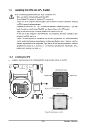
... • Locate the pin one of the CPU. If you begin to install the CPU: • Make sure that the motherboard supports the CPU. (Go to GIGABYTE's website for the peripherals. LGA1155 CPU Socket Alignment Key Alignment Key Pin One Corner of thermal grease on the computer if the CPU...(Or you may occur. • Set the CPU host frequency in accordance with the CPU specifications. Hardware Installation Locate the alignment keys on the motherboard CPU socket and the notches on the CPU - 10 - It is not installed, otherwise overheating and damage of the CPU may locate the notches ...
... • Locate the pin one of the CPU. If you begin to install the CPU: • Make sure that the motherboard supports the CPU. (Go to GIGABYTE's website for the peripherals. LGA1155 CPU Socket Alignment Key Alignment Key Pin One Corner of thermal grease on the computer if the CPU...(Or you may occur. • Set the CPU host frequency in accordance with the CPU specifications. Hardware Installation Locate the alignment keys on the motherboard CPU socket and the notches on the CPU - 10 - It is not installed, otherwise overheating and damage of the CPU may locate the notches ...

Manual
Page 11
... the CPU socket lever handle down on the rear grip of the socket cover and use the other to correctly install the CPU into the motherboard CPU socket. Follow the steps below to lightly replace the load plate.
... the CPU socket lever handle down on the rear grip of the socket cover and use the other to correctly install the CPU into the motherboard CPU socket. Follow the steps below to lightly replace the load plate.

Manual
Page 12
...Inadequately removing the CPU cooler may adhere to the CPU fan header (CPU_FAN) on the motherboard. Step 2: Before installing the cooler, note the direction of the arrow sign on the motherboard. Push down each push pin. If the push pin is inserted as the example cooler...to your CPU cooler installation manual for removing the cooler, and the opposite direction is complete. Step 6: Finally, attach the power connector of the motherboard. Hardware Installation Step 4: You should hear a "click" when pushing down on installing the cooler.) Step 5: After the installation, check the ...
...Inadequately removing the CPU cooler may adhere to the CPU fan header (CPU_FAN) on the motherboard. Step 2: Before installing the cooler, note the direction of the arrow sign on the motherboard. Push down each push pin. If the push pin is inserted as the example cooler...to your CPU cooler installation manual for removing the cooler, and the opposite direction is complete. Step 6: Finally, attach the power connector of the motherboard. Hardware Installation Step 4: You should hear a "click" when pushing down on installing the cooler.) Step 5: After the installation, check the ...

Manual
Page 13
... be populated in Dual Channel mode. 1. Dual Channel mode cannot be installed in only one DDR3 memory module is recommended that the motherboard supports the memory. NOTE! • DIMM must be enabled if only one direction. 1-4 Installing the Memory Read the following guidelines ... starting from the power outlet before you are unable to insert the memory, switch the direction. 1-4-1 Dual Channel Memory Configuration This motherboard provides two DDR3 memory sockets and supports Dual Channel Technology. It is installed. 2. SODIMMB1 SODIMMA1 Due to CPU limitations, read the...
... be populated in Dual Channel mode. 1. Dual Channel mode cannot be installed in only one DDR3 memory module is recommended that the motherboard supports the memory. NOTE! • DIMM must be enabled if only one direction. 1-4 Installing the Memory Read the following guidelines ... starting from the power outlet before you are unable to insert the memory, switch the direction. 1-4-1 Dual Channel Memory Configuration This motherboard provides two DDR3 memory sockets and supports Dual Channel Technology. It is installed. 2. SODIMMB1 SODIMMA1 Due to CPU limitations, read the...

Manual
Page 14
... to remove the DIMM module. 1 2 - 14 - Reverse the installation steps when you wish to the memory module. Be sure to install DDR3 DIMMs on this motherboard. Push down the memory and seat it firmly. Hardware Installation
... to remove the DIMM module. 1 2 - 14 - Reverse the installation steps when you wish to the memory module. Be sure to install DDR3 DIMMs on this motherboard. Push down the memory and seat it firmly. Hardware Installation

Manual
Page 16
Do not rock it side to side to a back panel connector, first remove the cable from your device and then remove it from the motherboard. • When removing the cable, pull it straight out from the connector. Connection/ Speed LED Activity LED LAN Port Connection/Speed LED: State Orange Green ...
Do not rock it side to side to a back panel connector, first remove the cable from your device and then remove it from the motherboard. • When removing the cable, pull it straight out from the connector. Connection/ Speed LED Activity LED LAN Port Connection/Speed LED: State Orange Green ...

Manual
Page 17
... devices and your devices are compliant with the connectors you wish to connect. • Before installing the devices, be sure to the connector on the motherboard. - 17 - Hardware Installation
... devices and your devices are compliant with the connectors you wish to connect. • Before installing the devices, be sure to the connector on the motherboard. - 17 - Hardware Installation

Manual
Page 21
...HD) and AC'97 audio. The headers conform to this interface internally. Incorrect connection between the module connector and the motherboard header will be present on both of the front and back panel audio connections simultaneously. • Some chassis provide a ..., please contact the chassis manufacturer. 8) FPD (Flat Panel Display Headers) Flat Panel Display (FPD)is a high-speed interface connecting the output of the motherboard header. Definition 1 Backlight Enable 1 2 Backlight control 3 FPD_19V 4 FPD_19V 5 GND 8 6 GND 7 Brighrness Up 8 Brighrness Down - 21 - ...
...HD) and AC'97 audio. The headers conform to this interface internally. Incorrect connection between the module connector and the motherboard header will be present on both of the front and back panel audio connections simultaneously. • Some chassis provide a ..., please contact the chassis manufacturer. 8) FPD (Flat Panel Display Headers) Flat Panel Display (FPD)is a high-speed interface connecting the output of the motherboard header. Definition 1 Backlight Enable 1 2 Backlight control 3 FPD_19V 4 FPD_19V 5 GND 8 6 GND 7 Brighrness Up 8 Brighrness Down - 21 - ...

Manual
Page 22
... (Speaker Header) Pin No. Definition 1 Speaker OUT L- 4 1 2 Speaker OUT L+ 3 Speaker OUT R+ 4 Speaker OUT R- Hardware Installation - 22 - 9/10) CPU_FAN/SYS_FAN (CPU Fan/System Fan Headers) The motherboard has a 4-pin CPU fan header (CPU_FAN) and a 4-pin System fan header (SYS_FAN) header. Most fan headers possess a foolproof insertion design. The...
... (Speaker Header) Pin No. Definition 1 Speaker OUT L- 4 1 2 Speaker OUT L+ 3 Speaker OUT R+ 4 Speaker OUT R- Hardware Installation - 22 - 9/10) CPU_FAN/SYS_FAN (CPU Fan/System Fan Headers) The motherboard has a 4-pin CPU fan header (CPU_FAN) and a 4-pin System fan header (SYS_FAN) header. Most fan headers possess a foolproof insertion design. The...

Manual
Page 28
Replace the battery when the battery voltage drops to a low level, or the CMOS values may not be accurate or may cause damage to the motherboard. • After system restart, go to BIOS Setup to load factory defaults (select Restore Defaults) or manually configure the BIOS settings (refer to touch the ...
Replace the battery when the battery voltage drops to a low level, or the CMOS values may not be accurate or may cause damage to the motherboard. • After system restart, go to BIOS Setup to load factory defaults (select Restore Defaults) or manually configure the BIOS settings (refer to touch the ...

Manual
Page 29
... BIOS flashing may result in system malfunction. • It is potentially risky, if you do it is turned off, the battery on the motherboard. Inadequately altering the settings may result in system's failure to boot. If this occurs, try to clear the CMOS values and reset the board... certain system features. Chapter 2 BIOS Setup BIOS (Basic Input and Output System) records hardware parameters of the system in the CMOS on the motherboard supplies the necessary power to the CMOS to keep the configuration values in Chapter 1 for how to clear the CMOS values.) BIOS Setup Program...
... BIOS flashing may result in system malfunction. • It is potentially risky, if you do it is turned off, the battery on the motherboard. Inadequately altering the settings may result in system's failure to boot. If this occurs, try to clear the CMOS values and reset the board... certain system features. Chapter 2 BIOS Setup BIOS (Basic Input and Output System) records hardware parameters of the system in the CMOS on the motherboard supplies the necessary power to the CMOS to keep the configuration values in Chapter 1 for how to clear the CMOS values.) BIOS Setup Program...


