
Manual
Page 1
... configuring the Smart Response Technology, all original data on the hard disk will see shall depend on your computer and press to enter BIOS Setup during the POST (Power-On Self-Test). Set PCH SATA Control Mode under the Integrated Peripherals menu to the SATA disk 4. Installing a ...menu options you will be lost once you enable RAID mode. Installing the operating system and drivers to RAID(XHD). Then save changes and exit BIOS Setup. The maximum cache memory size is recommended that you also need an SSD to enable the Intel Smart Response Technology • The Intel...
... configuring the Smart Response Technology, all original data on the hard disk will see shall depend on your computer and press to enter BIOS Setup during the POST (Power-On Self-Test). Set PCH SATA Control Mode under the Integrated Peripherals menu to the SATA disk 4. Installing a ...menu options you will be lost once you enable RAID mode. Installing the operating system and drivers to RAID(XHD). Then save changes and exit BIOS Setup. The maximum cache memory size is recommended that you also need an SSD to enable the Intel Smart Response Technology • The Intel...

Manual
Page 2
...fication area and double-click it to install the operating system. Installing the operating system and drivers to the SATA disk: After setting the BIOS, you can begin to open the Intel Rapid Storage Technology utility. - 2 - English 3.
...fication area and double-click it to install the operating system. Installing the operating system and drivers to the SATA disk: After setting the BIOS, you can begin to open the Intel Rapid Storage Technology utility. - 2 - English 3.
Manual
Page 3
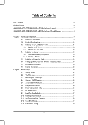
...rights reserved. For product-related information, check on our website at: http://www.gigabyte.com Identifying Your Motherboard Revision The revision number on your motherboard revision before updating motherboard BIOS, drivers, or when looking for technical information. No part of the product, ... motherboard is 1.0. Disclaimer Information in this : "REV: X.X." Documentation Classifications In order to assist in the use of this product, GIGABYTE provides the following types of documentations: For quick set-up of this manual may be reproduced, copied, translated, transmitted,...
...rights reserved. For product-related information, check on our website at: http://www.gigabyte.com Identifying Your Motherboard Revision The revision number on your motherboard revision before updating motherboard BIOS, drivers, or when looking for technical information. No part of the product, ... motherboard is 1.0. Disclaimer Information in this : "REV: X.X." Documentation Classifications In order to assist in the use of this product, GIGABYTE provides the following types of documentations: For quick set-up of this manual may be reproduced, copied, translated, transmitted,...
Manual
Page 4
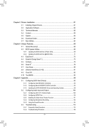
Table of Contents Box Contents...6 Optional Items...6 GA-Z68XP-UD3-iSSD/GA-Z68XP-UD3 Motherboard Layout 7 GA-Z68XP-UD3-iSSD/GA-Z68XP-UD3 Motherboard Block Diagram 8 Chapter 1 Hardware Installation 9 1-1 Installation Precautions 9 1-2 Product Specifications 10 1-3 Installing the CPU...Configuration 19 1-7 Back Panel Connectors 20 1-8 Internal Connectors 22 Chapter 2 BIOS Setup 33 2-1 Startup Screen 34 2-2 The Main Menu 35 2-3 MB Intelligent Tweaker(M.I.T 37 2-4 Standard CMOS Features 46 2-5 Advanced BIOS Features 48 2-6 Integrated Peripherals 50 2-7 Power Management Setup 53 2-8 PC...
Table of Contents Box Contents...6 Optional Items...6 GA-Z68XP-UD3-iSSD/GA-Z68XP-UD3 Motherboard Layout 7 GA-Z68XP-UD3-iSSD/GA-Z68XP-UD3 Motherboard Block Diagram 8 Chapter 1 Hardware Installation 9 1-1 Installation Precautions 9 1-2 Product Specifications 10 1-3 Installing the CPU...Configuration 19 1-7 Back Panel Connectors 20 1-8 Internal Connectors 22 Chapter 2 BIOS Setup 33 2-1 Startup Screen 34 2-2 The Main Menu 35 2-3 MB Intelligent Tweaker(M.I.T 37 2-4 Standard CMOS Features 46 2-5 Advanced BIOS Features 48 2-6 Integrated Peripherals 50 2-7 Power Management Setup 53 2-8 PC...
Manual
Page 5
... 62 3-4 Contact...63 3-5 System...63 3-6 Download Center 64 3-7 New Utilities...64 Chapter 4 Unique Features 65 4-1 Xpress Recovery2 65 4-2 BIOS Update Utilities 68 4-2-1 Updating the BIOS with the Q-Flash Utility 68 4-2-2 Updating the BIOS with the @BIOS Utility 71 4-3 EasyTune 6...72 4-4 Dynamic Energy Saver™ 2 73 4-5 Q-Share...75 4-6 Smart 6™ ...76 4-7 Auto Green...80 4-8 eXtreme...
... 62 3-4 Contact...63 3-5 System...63 3-6 Download Center 64 3-7 New Utilities...64 Chapter 4 Unique Features 65 4-1 Xpress Recovery2 65 4-2 BIOS Update Utilities 68 4-2-1 Updating the BIOS with the Q-Flash Utility 68 4-2-2 Updating the BIOS with the @BIOS Utility 71 4-3 EasyTune 6...72 4-4 Dynamic Energy Saver™ 2 73 4-5 Q-Share...75 4-6 Smart 6™ ...76 4-7 Auto Green...80 4-8 eXtreme...

Manual
Page 8
GA-Z68XP-UD3-iSSD/GA-Z68XP-UD3 Motherboard Block Diagram PCIe CLK (100 MHz) 1 PCI Express x16 or 2 PCI Express x8 LGA1155 CPU CPU CLK+/- (100 MHz) DDR3 2133/1866/1600/1333/... x1 3 PCI Express x1 PCIe to PCI Bridge DMI 2.0 FDI Intel® Z68 2 USB 3.0/2.0 2 USB 3.0/2.0 Etron EJ168 Etron EJ168 x1 x1 PCI Express Bus Dual BIOS HDMI 3 SATA 3Gb/s 1 SATA 3Gb/s 1 mSATA or Switch 2 SATA 6Gb/s 14 USB 2.0/1.1 PCI Bus VIA VT6308 2 IEEE 1394a CODEC LPC Bus iTE IT8728 COM Port...
GA-Z68XP-UD3-iSSD/GA-Z68XP-UD3 Motherboard Block Diagram PCIe CLK (100 MHz) 1 PCI Express x16 or 2 PCI Express x8 LGA1155 CPU CPU CLK+/- (100 MHz) DDR3 2133/1866/1600/1333/... x1 3 PCI Express x1 PCIe to PCI Bridge DMI 2.0 FDI Intel® Z68 2 USB 3.0/2.0 2 USB 3.0/2.0 Etron EJ168 Etron EJ168 x1 x1 PCI Express Bus Dual BIOS HDMI 3 SATA 3Gb/s 1 SATA 3Gb/s 1 mSATA or Switch 2 SATA 6Gb/s 14 USB 2.0/1.1 PCI Bus VIA VT6308 2 IEEE 1394a CODEC LPC Bus iTE IT8728 COM Port...
Manual
Page 12
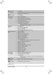
...Mbit flash ŠŠ Use of licensed AWARD BIOS ŠŠ Support for DualBIOS™ ŠŠ PnP 1.0a, DMI 2.0, SM BIOS 2.4, ACPI 1.0b Unique Features ŠŠ Support for @BIOS ŠŠ Support for Q-Flash ŠŠ Support for Xpress BIOS Rescue ŠŠ Support for Download Center ...138;Š Support for Microsoft® Windows 7/Vista/XP Form Factor ŠŠ ATX Form Factor; 30.5cm x 24.4cm * GIGABYTE reserves the right to make any changes to the integrated graphics port on the CPU/system cooler you install. Operating System ŠŠ ...
...Mbit flash ŠŠ Use of licensed AWARD BIOS ŠŠ Support for DualBIOS™ ŠŠ PnP 1.0a, DMI 2.0, SM BIOS 2.4, ACPI 1.0b Unique Features ŠŠ Support for @BIOS ŠŠ Support for Q-Flash ŠŠ Support for Xpress BIOS Rescue ŠŠ Support for Download Center ...138;Š Support for Microsoft® Windows 7/Vista/XP Form Factor ŠŠ ATX Form Factor; 30.5cm x 24.4cm * GIGABYTE reserves the right to make any changes to the integrated graphics port on the CPU/system cooler you install. Operating System ŠŠ ...
Manual
Page 16
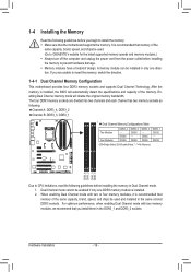
... the same capacity, brand, speed, and chips be installed in only one DDR3 memory module is installed, the BIOS will double the original memory bandwidth. Dual Channel mode cannot be used . (Go to GIGABYTE's website for the latest supported memory speeds and memory modules.) •• Always turn off the computer and...
... the same capacity, brand, speed, and chips be installed in only one DDR3 memory module is installed, the BIOS will double the original memory bandwidth. Dual Channel mode cannot be used . (Go to GIGABYTE's website for the latest supported memory speeds and memory modules.) •• Always turn off the computer and...
Manual
Page 18
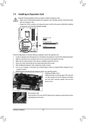
If necessary, go to BIOS Setup to make any required BIOS changes for your expansion card(s). 777 Install the driver provided with the expansion card in your operating system. • Installing a Graphics Card: Gently push down ...
If necessary, go to BIOS Setup to make any required BIOS changes for your expansion card(s). 777 Install the driver provided with the expansion card in your operating system. • Installing a Graphics Card: Gently push down ...

Manual
Page 24
... the correct orientation (the black connector wire is recommended that a system fan be lost. You may result in damage to keep the values (such as BIOS configurations, date, and time information) in accordance with an equivalent one minute. (Or use of the battery holder, making them short for one . self or...
... the correct orientation (the black connector wire is recommended that a system fan be lost. You may result in damage to keep the values (such as BIOS configurations, date, and time information) in accordance with an equivalent one minute. (Or use of the battery holder, making them short for one . self or...
Manual
Page 26
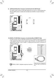
... instructions on configuring a RAID array. The Marvell 88SE9172 chip supports RAID 0 and RAID 1. Refer to your SATA hard drive. BUG RT Hardware Installation - 26 - DB_PORT BIOS Switcher (X58A-OC) 1 M_SATA mSATA DIP 1 23 1 DIP 1 23 1 DIP 1 23 1 Voltage measurement module(X58A-OC) PWM Switch (X58A-OC) DIP 1 23 PCIe power connector...
... instructions on configuring a RAID array. The Marvell 88SE9172 chip supports RAID 0 and RAID 1. Refer to your SATA hard drive. BUG RT Hardware Installation - 26 - DB_PORT BIOS Switcher (X58A-OC) 1 M_SATA mSATA DIP 1 23 1 DIP 1 23 1 DIP 1 23 1 Voltage measurement module(X58A-OC) PWM Switch (X58A-OC) DIP 1 23 PCIe power connector...

Manual
Page 27
.... Failure to do so may cause damage to the motherboard. •• After system restart, go to BIOS Setup to load factory defaults (select Load Optimized Defaults) or manually configure the BIOS settings (refer to clear the CMOS values (e.g. Open: Normal Short: Clear CMOS Values •• Always...values, place a jumper cap on your computer and unplug the power cord from the jumper. date information and BIOS configurations) and reset the CMOS values to touch the two pins for BIOS configurations). - 27 - 11) COMA (Serial Port Header) The COM header can provide one serial port ...
.... Failure to do so may cause damage to the motherboard. •• After system restart, go to BIOS Setup to load factory defaults (select Load Optimized Defaults) or manually configure the BIOS settings (refer to clear the CMOS values (e.g. Open: Normal Short: Clear CMOS Values •• Always...values, place a jumper cap on your computer and unplug the power cord from the jumper. date information and BIOS configurations) and reset the CMOS values to touch the two pins for BIOS configurations). - 27 - 11) COMA (Serial Port Header) The COM header can provide one serial port ...

Manual
Page 28
... different patterns to indicate the problem. The LED keeps blinking when the sys- When connecting your system using the power switch (refer to Chapter 2, "BIOS Setup," "Power Management Setup," for information about beep codes. •• HD (Hard Drive Activity LED, Blue) Connects to the hard drive activity... LED on the chassis front panel. The LED is off when the system is detected, the BIOS may configure the way to turn off (S5). •• PW (Power Switch, Red): Connects to the power switch on the chassis front...
... different patterns to indicate the problem. The LED keeps blinking when the sys- When connecting your system using the power switch (refer to Chapter 2, "BIOS Setup," "Power Management Setup," for information about beep codes. •• HD (Hard Drive Activity LED, Blue) Connects to the hard drive activity... LED on the chassis front panel. The LED is off when the system is detected, the BIOS may configure the way to turn off (S5). •• PW (Power Switch, Red): Connects to the power switch on the chassis front...
Manual
Page 29
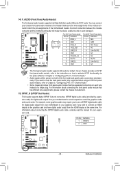
... 5 LINE2_R 4 NC 5 Line Out (R) 6 GND 6 NC 7 FAUDIO_JD 7 NC 8 No Pin 8 No Pin 9 LINE2_L 9 Line Out (L) 10 GND 10 NC DIP 1 23 1 DIP 1 23 1 DIP 1 23 1 BIOS Switcher (X58A-OC) DB_P•O•RTThe front panel audio header supports HD audio by expansionPcCaIerdposw)efrocrodnnigecittaorl(aSuATdAio)(Xo5u8Atp-OuCt)from the HDMI display at...
... 5 LINE2_R 4 NC 5 Line Out (R) 6 GND 6 NC 7 FAUDIO_JD 7 NC 8 No Pin 8 No Pin 9 LINE2_L 9 Line Out (L) 10 GND 10 NC DIP 1 23 1 DIP 1 23 1 DIP 1 23 1 BIOS Switcher (X58A-OC) DB_P•O•RTThe front panel audio header supports HD audio by expansionPcCaIerdposw)efrocrodnnigecittaorl(aSuATdAio)(Xo5u8Atp-OuCt)from the HDMI display at...

Manual
Page 30
... conforms to the USB bracket. Definition 1 VBUS 11 D2+ 2 SSRX1- 12 D2- 3 SSRX1+ 13 GND 4 GND 14 SSTX2+ 5 SSTX1- 15 SSTX2- 6 SSTX1+ 16 GND DB_PORT BIOS 7 GND 17 SSRX2+ 8 D1- 18 SSRX2- 9 D1+ 19 VBUS 10 NC 20 No Pin When the system is in S4/S5 mode, only the USB...
... conforms to the USB bracket. Definition 1 VBUS 11 D2+ 2 SSRX1- 12 D2- 3 SSRX1+ 13 GND 4 GND 14 SSTX2+ 5 SSTX1- 15 SSTX2- 6 SSTX1+ 16 GND DB_PORT BIOS 7 GND 17 SSRX2+ 8 D1- 18 SSRX2- 9 D1+ 19 VBUS 10 NC 20 No Pin When the system is in S4/S5 mode, only the USB...

Manual
Page 32
1 20) TPM (Trusted Platform Module Header) You may connect a TPM (Trusted Platform Module) to this header. Definition DIP 11 LAD0 1 23 12 GND PCIe power connector (SATA)(X58A-OC) 13 NC 14 ID 15 SB3V 16 SERIRQ 17 GND 18 NC 19 NC 20 SUSCLK Hardware Installation - 32 - DB_PORT BIOS Switc 1 1 19 TPM w/housing 20 Pin No. Definition 1 LCLK 2 GND 3 LFRAME 4 No Pin 5 LRESET 6 NC 7 LAD3 8 LAD2 9 VCC3 10 LAD1 1 Voltage measurement module(X58A-OC) PWM Swi DIP 2 Pin No.
1 20) TPM (Trusted Platform Module Header) You may connect a TPM (Trusted Platform Module) to this header. Definition DIP 11 LAD0 1 23 12 GND PCIe power connector (SATA)(X58A-OC) 13 NC 14 ID 15 SB3V 16 SERIRQ 17 GND 18 NC 19 NC 20 SUSCLK Hardware Installation - 32 - DB_PORT BIOS Switc 1 1 19 TPM w/housing 20 Pin No. Definition 1 LCLK 2 GND 3 LFRAME 4 No Pin 5 LRESET 6 NC 7 LAD3 8 LAD2 9 VCC3 10 LAD1 1 Voltage measurement module(X58A-OC) PWM Swi DIP 2 Pin No.

Manual
Page 33
... chapter or introductions of the system in the CMOS on the motherboard supplies the necessary power to the CMOS to boot. Chapter 2 BIOS Setup BIOS (Basic Input and Output System) records hardware parameters of the battery/ clearing CMOS jumper in Chapter 1 for the beep codes description....) during system startup, saving system parameters and loading operating system, etc. To see more advanced BIOS Setup menu options, you can press + in the CMOS. To upgrade the BIOS, use either the GIGABYTE Q-Flash or @BIOS utility. • Q-Flash allows the user to activate certain system features.
... chapter or introductions of the system in the CMOS on the motherboard supplies the necessary power to the CMOS to boot. Chapter 2 BIOS Setup BIOS (Basic Input and Output System) records hardware parameters of the battery/ clearing CMOS jumper in Chapter 1 for the beep codes description....) during system startup, saving system parameters and loading operating system, etc. To see more advanced BIOS Setup menu options, you can press + in the CMOS. To upgrade the BIOS, use either the GIGABYTE Q-Flash or @BIOS utility. • Q-Flash allows the user to activate certain system features.
Manual
Page 34
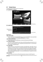
...Xpress Recovery2 during the POST. The LOGO Screen (Default) B. The POST Screen Award Modular BIOS v6.00PG Copyright (C) 1984-2011, Award Software, Inc. Motherboard Model BIOS Version Z68XP-UD3 F1ax . . . . : BIOS Setup : XpressRecovery2 : Boot Menu : Qflash 05/12/2011-Z68-7A89WG0CC-00 Function Keys ...Function Keys Function Keys: : POST SCREEN Press the key to show the BIOS POST screen at system startup, refer...
...Xpress Recovery2 during the POST. The LOGO Screen (Default) B. The POST Screen Award Modular BIOS v6.00PG Copyright (C) 1984-2011, Award Software, Inc. Motherboard Model BIOS Version Z68XP-UD3 F1ax . . . . : BIOS Setup : XpressRecovery2 : Boot Menu : Qflash 05/12/2011-Z68-7A89WG0CC-00 Function Keys ...Function Keys Function Keys: : POST SCREEN Press the key to show the BIOS POST screen at system startup, refer...

Manual
Page 35
...your system to its defaults. • The BIOS Setup menus described in this chapter are for the menu. Use arrow keys to move among the items and press to accept or enter a sub-menu. (Sample BIOS Version: GA-Z68XP-UD3 Flax) CMOS Setup Utility-Copyright (C) 1984-...2011 Award Software MB Intelligent Tweaker(M.I.T.) Standard CMOS Features Advanced BIOS Features Integrated Peripherals Power Management Setup PC...
...your system to its defaults. • The BIOS Setup menus described in this chapter are for the menu. Use arrow keys to move among the items and press to accept or enter a sub-menu. (Sample BIOS Version: GA-Z68XP-UD3 Flax) CMOS Setup Utility-Copyright (C) 1984-...2011 Award Software MB Intelligent Tweaker(M.I.T.) Standard CMOS Features Advanced BIOS Features Integrated Peripherals Power Management Setup PC...

Manual
Page 36
...to configure the system time and date, hard drive types, and the type of errors that stop the system boot, etc. Advanced BIOS Features Use this menu to configure the device boot order, advanced features available on the CPU, and the primary display adapter. Integrated ... USB, integrated audio, and integrated LAN, etc. Power Management Setup Use this menu to configure all changes and the previous settings remain in BIOS Setup. Set User Password Change, set , or disable password. It allows you can also carry out this task.) Exit Without Saving...
...to configure the system time and date, hard drive types, and the type of errors that stop the system boot, etc. Advanced BIOS Features Use this menu to configure the device boot order, advanced features available on the CPU, and the primary display adapter. Integrated ... USB, integrated audio, and integrated LAN, etc. Power Management Setup Use this menu to configure all changes and the previous settings remain in BIOS Setup. Set User Password Change, set , or disable password. It allows you can also carry out this task.) Exit Without Saving...


