
Manual
Page 1
... to RAID(XHD). Set PCH SATA Control Mode under the Integrated Peripherals menu to the SATA disk 4. Then save changes and exit BIOS Setup. Launching the Intel Rapid Storage Technology utility to enable the Intel Smart Response Technology • The Intel Smart Response Technology requires... need an SSD to the SATA disk. • Supported operating systems include Windows 7 and Windows Vista. • If you have and the BIOS version. - 1 - CMOS Setup Utility-Copyright (C) 1984-2011 Award Software Integrated Peripherals eXtreme Hard Drive (XHD) PCH SATA Control Mode OROM UI...
... to RAID(XHD). Set PCH SATA Control Mode under the Integrated Peripherals menu to the SATA disk 4. Then save changes and exit BIOS Setup. Launching the Intel Rapid Storage Technology utility to enable the Intel Smart Response Technology • The Intel Smart Response Technology requires... need an SSD to the SATA disk. • Supported operating systems include Windows 7 and Windows Vista. • If you have and the BIOS version. - 1 - CMOS Setup Utility-Copyright (C) 1984-2011 Award Software Integrated Peripherals eXtreme Hard Drive (XHD) PCH SATA Control Mode OROM UI...

Manual
Page 2
Installing the operating system and drivers to the SATA disk: After setting the BIOS, you can begin to open the Intel Rapid Storage Technology utility. - 2 - Launching the Intel Rapid Storage Technology utility to install all motherboard drivers, including the ...
Installing the operating system and drivers to the SATA disk: After setting the BIOS, you can begin to open the Intel Rapid Storage Technology utility. - 2 - Launching the Intel Rapid Storage Technology utility to install all motherboard drivers, including the ...
Manual
Page 3
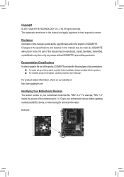
... by copyright laws and is 1.0. Changes to their respective owners. Documentation Classifications In order to assist in this product, GIGABYTE provides the following types of documentations: For quick set-up of this manual are legally registered to the specifications...notice. Example: For product-related information, check on our website at: http://www.gigabyte.com Identifying Your Motherboard Revision The revision number on your motherboard revision before updating motherboard BIOS, drivers, or when looking for technical information. Copyright © 2011 GIGA-BYTE ...
... by copyright laws and is 1.0. Changes to their respective owners. Documentation Classifications In order to assist in this product, GIGABYTE provides the following types of documentations: For quick set-up of this manual are legally registered to the specifications...notice. Example: For product-related information, check on our website at: http://www.gigabyte.com Identifying Your Motherboard Revision The revision number on your motherboard revision before updating motherboard BIOS, drivers, or when looking for technical information. Copyright © 2011 GIGA-BYTE ...
Manual
Page 4
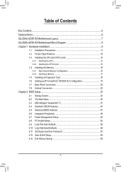
Table of Contents Box Contents...6 Optional Items...6 GA-Z68X-UD3R-B3 Motherboard Layout 7 GA-Z68X-UD3R-B3 Motherboard Block Diagram 8 Chapter 1 Hardware Installation 9 1-1 Installation Precautions 9 1-2 Product Specifications 10 1-3 Installing the CPU and CPU Cooler ... SLI Configuration 19 1-7 Back Panel Connectors 20 1-8 Internal Connectors 22 Chapter 2 BIOS Setup 33 2-1 Startup Screen 34 2-2 The Main Menu 35 2-3 MB Intelligent Tweaker(M.I.T 37 2-4 Standard CMOS Features 45 2-5 Advanced BIOS Features 47 2-6 Integrated Peripherals 49 2-7 Power Management Setup 52 2-8 PC Health ...
Table of Contents Box Contents...6 Optional Items...6 GA-Z68X-UD3R-B3 Motherboard Layout 7 GA-Z68X-UD3R-B3 Motherboard Block Diagram 8 Chapter 1 Hardware Installation 9 1-1 Installation Precautions 9 1-2 Product Specifications 10 1-3 Installing the CPU and CPU Cooler ... SLI Configuration 19 1-7 Back Panel Connectors 20 1-8 Internal Connectors 22 Chapter 2 BIOS Setup 33 2-1 Startup Screen 34 2-2 The Main Menu 35 2-3 MB Intelligent Tweaker(M.I.T 37 2-4 Standard CMOS Features 45 2-5 Advanced BIOS Features 47 2-6 Integrated Peripherals 49 2-7 Power Management Setup 52 2-8 PC Health ...
Manual
Page 5
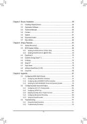
... 60 3-4 Contact...61 3-5 System...61 3-6 Download Center 62 3-7 New Utilities...62 Chapter 4 Unique Features 63 4-1 Xpress Recovery2 63 4-2 BIOS Update Utilities 66 4-2-1 Updating the BIOS with the Q-Flash Utility 66 4-2-2 Updating the BIOS with the @BIOS Utility 69 4-3 EasyTune 6...70 4-4 Dynamic Energy Saver™ 2 71 4-5 Q-Share...73 4-6 Smart 6™ ...74 4-7 Auto Green...78 4-8 eXtreme...
... 60 3-4 Contact...61 3-5 System...61 3-6 Download Center 62 3-7 New Utilities...62 Chapter 4 Unique Features 63 4-1 Xpress Recovery2 63 4-2 BIOS Update Utilities 66 4-2-1 Updating the BIOS with the Q-Flash Utility 66 4-2-2 Updating the BIOS with the @BIOS Utility 69 4-3 EasyTune 6...70 4-4 Dynamic Energy Saver™ 2 71 4-5 Q-Share...73 4-6 Smart 6™ ...74 4-7 Auto Green...78 4-8 eXtreme...
Manual
Page 8
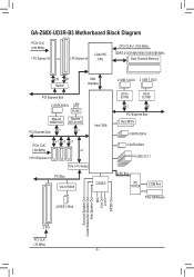
GA-Z68X-UD3R-B3 Motherboard Block Diagram PCIe CLK (100 MHz) 1 PCI Express x16 or 2 PCI Express x8 LGA1155 CPU CPU CLK+/- (100 MHz) DDR3 2133/1866/1600/1333/... to PCI Bridge Intel® Z68 PCI Bus VIA VT6308 CODEC 2 IEEE 1394a 2 USB 3.0/2.0 2 USB 3.0/2.0 Etron EJ168 Etron EJ168 x1 x1 PCI Express Bus Dual BIOS 4 SATA 3Gb/s 2 SATA 6Gb/s 14 USB 2.0/1.1 LPC Bus iTE IT8728 COM Port PS/2 KB/Mouse Surround Speaker Out Center/Subwoofer Speaker Out Side Speaker Out...
GA-Z68X-UD3R-B3 Motherboard Block Diagram PCIe CLK (100 MHz) 1 PCI Express x16 or 2 PCI Express x8 LGA1155 CPU CPU CLK+/- (100 MHz) DDR3 2133/1866/1600/1333/... to PCI Bridge Intel® Z68 PCI Bus VIA VT6308 CODEC 2 IEEE 1394a 2 USB 3.0/2.0 2 USB 3.0/2.0 Etron EJ168 Etron EJ168 x1 x1 PCI Express Bus Dual BIOS 4 SATA 3Gb/s 2 SATA 6Gb/s 14 USB 2.0/1.1 LPC Bus iTE IT8728 COM Port PS/2 KB/Mouse Surround Speaker Out Center/Subwoofer Speaker Out Side Speaker Out...
Manual
Page 12
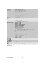
...Mbit flash ŠŠ Use of licensed AWARD BIOS ŠŠ Support for DualBIOS™ ŠŠ PnP 1.0a, DMI 2.0, SM BIOS 2.4, ACPI 1.0b Unique Features ŠŠ Support for @BIOS ŠŠ Support for Q-Flash ŠŠ Support for Xpress BIOS Rescue ŠŠ Support for Download Center ...138; Support for Microsoft® Windows 7/Vista/XP Form Factor ŠŠ ATX Form Factor; 30.5cm x 24.4cm * GIGABYTE reserves the right to make any changes to the product specifications and product-related information without prior notice. Hardware Installation - 12 -
...Mbit flash ŠŠ Use of licensed AWARD BIOS ŠŠ Support for DualBIOS™ ŠŠ PnP 1.0a, DMI 2.0, SM BIOS 2.4, ACPI 1.0b Unique Features ŠŠ Support for @BIOS ŠŠ Support for Q-Flash ŠŠ Support for Xpress BIOS Rescue ŠŠ Support for Download Center ...138; Support for Microsoft® Windows 7/Vista/XP Form Factor ŠŠ ATX Form Factor; 30.5cm x 24.4cm * GIGABYTE reserves the right to make any changes to the product specifications and product-related information without prior notice. Hardware Installation - 12 -
Manual
Page 16
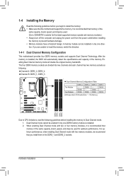
... have a foolproof design. For optimum performance, when enabling Dual Channel mode with two or four memory modules, it is installed, the BIOS will double the original memory bandwidth. After the memory is recommended that the motherboard supports the memory. When enabling Dual Channel mode with two... memory modules, we recommend that memory of the same capacity, brand, speed, and chips be used . (Go to GIGABYTE's website for optimum performance. DS/SS DS/SS DDR3_1 DS/SS - It is installed. 2. Hardware Installation - 16 - DS/SS DDR3_3 - The...
... have a foolproof design. For optimum performance, when enabling Dual Channel mode with two or four memory modules, it is installed, the BIOS will double the original memory bandwidth. After the memory is recommended that the motherboard supports the memory. When enabling Dual Channel mode with two... memory modules, we recommend that memory of the same capacity, brand, speed, and chips be used . (Go to GIGABYTE's website for optimum performance. DS/SS DS/SS DDR3_1 DS/SS - It is installed. 2. Hardware Installation - 16 - DS/SS DDR3_3 - The...
Manual
Page 18
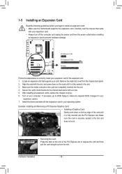
... the slot. 1-5 Installing an Expansion Card Read the following guidelines before installing an expansion card to prevent hardware damage. If necessary, go to BIOS Setup to make any required BIOS changes for your expansion card(s). 777 Install the driver provided with your operating system. Hardware Installation - 18 - Remove the metal slot cover...
... the slot. 1-5 Installing an Expansion Card Read the following guidelines before installing an expansion card to prevent hardware damage. If necessary, go to BIOS Setup to make any required BIOS changes for your expansion card(s). 777 Install the driver provided with your operating system. Hardware Installation - 18 - Remove the metal slot cover...
Manual
Page 24
... values may not be installed inside the chassis. Hardware Installation - 24 - Replace the battery when the battery voltage drops to keep the values (such as BIOS configurations, date, and time information) in the power cord and restart your CPU and system from the battery holder and wait for 5 seconds.) 333 Replace...
... values may not be installed inside the chassis. Hardware Installation - 24 - Replace the battery when the battery voltage drops to keep the values (such as BIOS configurations, date, and time information) in the power cord and restart your CPU and system from the battery holder and wait for 5 seconds.) 333 Replace...
Manual
Page 27
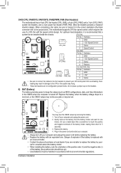
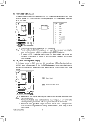
... when the sys- The LED is off when the system is operating. When connecting your system using the power switch (refer to Chapter 2, "BIOS Setup," "Power Management Setup," for information about beep codes. •• HD (Hard Drive Activity LED, Blue) Connects to the hard drive... reset switch, power LED, hard drive activity LED, speaker and etc. One single short beep will be heard if no problem is detected, the BIOS may differ by issuing a beep code. Hardware Installation This function requires a chassis with a chassis intrusion switch/sensor. If a problem is detected at...
... when the sys- The LED is off when the system is operating. When connecting your system using the power switch (refer to Chapter 2, "BIOS Setup," "Power Management Setup," for information about beep codes. •• HD (Hard Drive Activity LED, Blue) Connects to the hard drive... reset switch, power LED, hard drive activity LED, speaker and etc. One single short beep will be heard if no problem is detected, the BIOS may differ by issuing a beep code. Hardware Installation This function requires a chassis with a chassis intrusion switch/sensor. If a problem is detected at...
Manual
Page 28
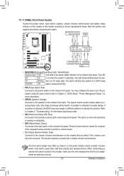
... 5 LINE2_R 4 NC 5 Line Out (R) 6 GND 6 NC 7 FAUDIO_JD 7 NC 8 No Pin 8 No Pin 9 LINE2_L 9 Line Out (L) 10 GND 10 NC DIP 1 23 1 DIP 1 23 1 DIP 1 23 1 BIOS Switcher (X58A-OC) DB_P•O•RTThe front panel audio header supports HD audio by expansionPcCaIerdposw)efrocrodnnigecittaorl(aSuATdAio)(Xo5u8Atp-OuCt)from the HDMI display at...
... 5 LINE2_R 4 NC 5 Line Out (R) 6 GND 6 NC 7 FAUDIO_JD 7 NC 8 No Pin 8 No Pin 9 LINE2_L 9 Line Out (L) 10 GND 10 NC DIP 1 23 1 DIP 1 23 1 DIP 1 23 1 BIOS Switcher (X58A-OC) DB_P•O•RTThe front panel audio header supports HD audio by expansionPcCaIerdposw)efrocrodnnigecittaorl(aSuATdAio)(Xo5u8Atp-OuCt)from the HDMI display at...
Manual
Page 29
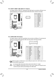
... to the USB bracket. - 29 - Definition 1 VBUS 11 D2+ 2 SSRX1- 12 D2- 3 SSRX1+ 13 GND 4 GND 14 SSTX2+ 5 SSTX1- 15 SSTX2- 6 SSTX1+ 16 GND DB_PORT BIOS 7 GND 17 SSRX2+ 8 D1- 18 SSRX2- 9 D1+ 19 VBUS 10 NC 20 No Pin When the system is in S4/S5 mode, only the USB...
... to the USB bracket. - 29 - Definition 1 VBUS 11 D2+ 2 SSRX1- 12 D2- 3 SSRX1+ 13 GND 4 GND 14 SSTX2+ 5 SSTX1- 15 SSTX2- 6 SSTX1+ 16 GND DB_PORT BIOS 7 GND 17 SSRX2+ 8 D1- 18 SSRX2- 9 D1+ 19 VBUS 10 NC 20 No Pin When the system is in S4/S5 mode, only the USB...
Manual
Page 30
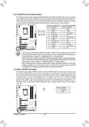
...few seconds. Failure to do so may cause damage to the motherboard. •• After system restart, go to BIOS Setup to load factory defaults (select Load Optimized Defaults) or manually configure the BIOS settings (refer to factory defaults. For purchasing the optional IEEE 1394a bracket, please con- Definition 1 TPA+ 9 1...provide one end of the cable to remove the jumper cap from the power outlet to prevent damage to touch the two pins for BIOS configurations). To clear the CMOS values, place a jumper cap on your computer and then attach the other end of the device ...
...few seconds. Failure to do so may cause damage to the motherboard. •• After system restart, go to BIOS Setup to load factory defaults (select Load Optimized Defaults) or manually configure the BIOS settings (refer to factory defaults. For purchasing the optional IEEE 1394a bracket, please con- Definition 1 TPA+ 9 1...provide one end of the cable to remove the jumper cap from the power outlet to prevent damage to touch the two pins for BIOS configurations). To clear the CMOS values, place a jumper cap on your computer and then attach the other end of the device ...
Manual
Page 31
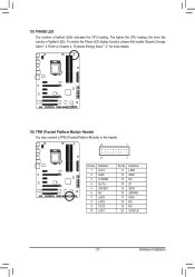
... indicates the CPU loading. To enable the Phase LED display function, please first enable Dynamic Energy Saver™ 2. Refer to this header. Hardware Installation DB_PORT BIOS Switc 1 1 19 TPM w/housing 20 Pin No. 1 2 3 4 5 6 7 8 9 10 Definition LCLK GND LFRAME No Pin LRESET NC LAD3 LAD2 VCC3 LAD1 1 Voltage measurement module(X58A-OC...
... indicates the CPU loading. To enable the Phase LED display function, please first enable Dynamic Energy Saver™ 2. Refer to this header. Hardware Installation DB_PORT BIOS Switc 1 1 19 TPM w/housing 20 Pin No. 1 2 3 4 5 6 7 8 9 10 Definition LCLK GND LFRAME No Pin LRESET NC LAD3 LAD2 VCC3 LAD1 1 Voltage measurement module(X58A-OC...
Manual
Page 33
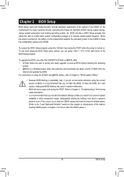
... settings (unless you can press + in system's failure to Chapter 4, "BIOS Update Utilities." • Because BIOS flashing is recommended that you do it with caution. To upgrade the BIOS, use either the GIGABYTE Q-Flash or @BIOS utility. • Q-Flash allows the user to clear the CMOS values.) ...- 33 - To flash the BIOS, do not encounter problems using the Q-Flash and @BIOS utilities, refer to boot. Inadequate BIOS flashing may result in...
... settings (unless you can press + in system's failure to Chapter 4, "BIOS Update Utilities." • Because BIOS flashing is recommended that you do it with caution. To upgrade the BIOS, use either the GIGABYTE Q-Flash or @BIOS utility. • Q-Flash allows the user to clear the CMOS values.) ...- 33 - To flash the BIOS, do not encounter problems using the Q-Flash and @BIOS utilities, refer to boot. Inadequate BIOS flashing may result in...
Manual
Page 34
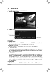
.... : XPRESS RECOVERY2 If you to set the first boot device without having to enter BIOS Setup first. A. Note: The setting in Boot Menu. Motherboard Model BIOS Version Z68X-UD3R-B3 F1a . . . . : BIOS Setup : XpressRecovery2 : Boot Menu : Qflash 04/13/2011-Z68-7A89WG05C-00 Function Keys Function Keys Function Keys: : POST SCREEN Press the key to accept...
.... : XPRESS RECOVERY2 If you to set the first boot device without having to enter BIOS Setup first. A. Note: The setting in Boot Menu. Motherboard Model BIOS Version Z68X-UD3R-B3 F1a . . . . : BIOS Setup : XpressRecovery2 : Boot Menu : Qflash 04/13/2011-Z68-7A89WG05C-00 Function Keys Function Keys Function Keys: : POST SCREEN Press the key to accept...
Manual
Page 35
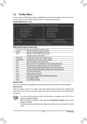
... numeric value or make changes Decrease the numeric value or make changes Show descriptions of function keys available for reference only and may differ by BIOS version. - 35 - Submenu Help While in this chapter are for the menu. Use arrow keys to move among the items and press to ... Setup Exit Without Saving ESC: Quit F8: Q-Flash Select Item F10: Save & Exit Setup Change CPU's Clock & Voltage F11: Save CMOS to BIOS F12: Load CMOS from BIOS Main Menu Help The on-screen description of a highlighted setup option is displayed on the right side of the submenu. • If you...
... numeric value or make changes Decrease the numeric value or make changes Show descriptions of function keys available for reference only and may differ by BIOS version. - 35 - Submenu Help While in this chapter are for the menu. Use arrow keys to move among the items and press to ... Setup Exit Without Saving ESC: Quit F8: Q-Flash Select Item F10: Save & Exit Setup Change CPU's Clock & Voltage F11: Save CMOS to BIOS F12: Load CMOS from BIOS Main Menu Help The on-screen description of a highlighted setup option is displayed on the right side of the submenu. • If you...
Manual
Page 36
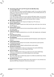
...menu to configure the system time and date, hard drive types, and the type of errors that stop the system boot, etc. Advanced BIOS Features Use this menu to configure the device boot order, advanced features available on the CPU, and the primary display adapter. Integrated Peripherals...you to make changes. Save & Exit Setup Save all the changes made in effect. It allows you to restrict access to the system and BIOS Setup. Pressing to 8 profiles (Profile 1-8) and name each profile. First select the profile you wish to load, then press to complete. MB...
...menu to configure the system time and date, hard drive types, and the type of errors that stop the system boot, etc. Advanced BIOS Features Use this menu to configure the device boot order, advanced features available on the CPU, and the primary display adapter. Integrated Peripherals...you to make changes. Save & Exit Setup Save all the changes made in effect. It allows you to restrict access to the system and BIOS Setup. Pressing to 8 profiles (Profile 1-8) and name each profile. First select the profile you wish to load, then press to complete. MB...
Manual
Page 37
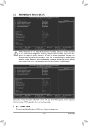
...Miscellaneous Settings [Press Enter] [Press Enter] [Press Enter] [Press Enter] [Press Enter] Item Help Menu Level BIOS Version BCLK CPU Frequency Memory Frequency Total Memory Size CPU Temperature Vcore DRAM Voltage F1a 99.80 MHz 3193.85 MHz 1330.... Settings [Press Enter] [Press Enter] [Press Enter] [Press Enter] [Press Enter] Item Help Menu Level BIOS Version BCLK CPU Frequency Memory Frequency Total Memory Size CPU Temperature Vcore DRAM Voltage F1a 99.80 MHz 3193.85 MHz 1330....
...Miscellaneous Settings [Press Enter] [Press Enter] [Press Enter] [Press Enter] [Press Enter] Item Help Menu Level BIOS Version BCLK CPU Frequency Memory Frequency Total Memory Size CPU Temperature Vcore DRAM Voltage F1a 99.80 MHz 3193.85 MHz 1330.... Settings [Press Enter] [Press Enter] [Press Enter] [Press Enter] [Press Enter] Item Help Menu Level BIOS Version BCLK CPU Frequency Memory Frequency Total Memory Size CPU Temperature Vcore DRAM Voltage F1a 99.80 MHz 3193.85 MHz 1330....


