
Manual
Page 3
... be reproduced, copied, translated, transmitted, or published in this manual are legally registered to use of this product, GIGABYTE provides the following types of documentations: For quick set-up of this : "REV: X.X." Documentation Classifications In order ...motherboard revision before updating motherboard BIOS, drivers, or when looking for technical information. The trademarks mentioned in this manual may be made by GIGABYTE without GIGABYTE's prior written permission. For example, "REV: 1.0" means the revision of GIGABYTE. Disclaimer Information in any...
... be reproduced, copied, translated, transmitted, or published in this manual are legally registered to use of this product, GIGABYTE provides the following types of documentations: For quick set-up of this : "REV: X.X." Documentation Classifications In order ...motherboard revision before updating motherboard BIOS, drivers, or when looking for technical information. The trademarks mentioned in this manual may be made by GIGABYTE without GIGABYTE's prior written permission. For example, "REV: 1.0" means the revision of GIGABYTE. Disclaimer Information in any...

Manual
Page 4
Table of Contents Box Contents...6 Optional Items...6 GA-X58A-UD9 Motherboard Layout 7 GA-X58A-UD9 Motherboard Block Diagram 8 Chapter 1 Hardware Installation 9 1-1 Installation Precautions 9 1-2 Product Specifications 10 1-3 Installing the CPU and CPU Cooler 13 ... Connectors 23 1-10 Onboard LEDs and Switches 25 1-11 Internal Connectors 28 Chapter 2 BIOS Setup 39 2-1 Startup Screen 40 2-2 The Main Menu 41 2-3 MB Intelligent Tweaker(M.I.T 43 2-4 Standard CMOS Features 53 2-5 Advanced BIOS Features 55 2-6 Integrated Peripherals 57 2-7 Power Management Setup 61 2-8 PC Health Status...
Table of Contents Box Contents...6 Optional Items...6 GA-X58A-UD9 Motherboard Layout 7 GA-X58A-UD9 Motherboard Block Diagram 8 Chapter 1 Hardware Installation 9 1-1 Installation Precautions 9 1-2 Product Specifications 10 1-3 Installing the CPU and CPU Cooler 13 ... Connectors 23 1-10 Onboard LEDs and Switches 25 1-11 Internal Connectors 28 Chapter 2 BIOS Setup 39 2-1 Startup Screen 40 2-2 The Main Menu 41 2-3 MB Intelligent Tweaker(M.I.T 43 2-4 Standard CMOS Features 53 2-5 Advanced BIOS Features 55 2-6 Integrated Peripherals 57 2-7 Power Management Setup 61 2-8 PC Health Status...

Manual
Page 5
...72 Chapter 4 Unique Features 73 4-1 Xpress Recovery2 73 4-2 BIOS Update Utilities 76 4-2-1 Updating the BIOS with the Q-Flash Utility 76 4-2-2 Updating the BIOS with the @BIOS Utility 79 4-3 EasyTune 6...80 4-4 Dynamic Energy Saver™... 2 81 4-5 Q-Share...83 4-6 Smart 6™ ...84 4-7 Auto Green...87 4-8 eXtreme Hard Drive (X.H.D 88 4-9 Teaming 89 Chapter 5 Appendix...91 5-1 Configuring SATA Hard Drive(s 91 5-1-1 Configuring Intel ICH10R SATA Controllers 91 5-1-2 Configuring JMicron JMB362/GIGABYTE...
...72 Chapter 4 Unique Features 73 4-1 Xpress Recovery2 73 4-2 BIOS Update Utilities 76 4-2-1 Updating the BIOS with the Q-Flash Utility 76 4-2-2 Updating the BIOS with the @BIOS Utility 79 4-3 EasyTune 6...80 4-4 Dynamic Energy Saver™... 2 81 4-5 Q-Share...83 4-6 Smart 6™ ...84 4-7 Auto Green...87 4-8 eXtreme Hard Drive (X.H.D 88 4-9 Teaming 89 Chapter 5 Appendix...91 5-1 Configuring SATA Hard Drive(s 91 5-1-1 Configuring Intel ICH10R SATA Controllers 91 5-1-2 Configuring JMicron JMB362/GIGABYTE...
Manual
Page 8
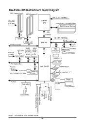
GA-X58A-UD9 Motherboard Block Diagram 3 PCI Express x8 4 PCI Express x16 CPU CLK+/- (133 MHz) PCIe CLK ... x1 x1 x1 PCI Express Bus PCIe CLK (100 MHz) 2 SATA 3Gb/s ATA-133/100/66/33 IDE Channel x1 GIGABYTE SATA2 QPI Interface IOH CLK (133 MHz) Intel® X58 PCI Express Bus x1 NEC D720200F1 x1 PCIe CLK Marvell 9128... (100 MHz) 2 SATA 6Gb/s Intel® ICH10R 2 USB 3.0/2.0 Dual BIOS 6 SATA 3Gb/s 12 USB 2.0/1.1 (Note) PCI Bus TSB43AB23 CODEC LPC Bus IT8720 Floppy PS/2 KB/Mouse 3 IEEE 1394a Surround Speaker ...
GA-X58A-UD9 Motherboard Block Diagram 3 PCI Express x8 4 PCI Express x16 CPU CLK+/- (133 MHz) PCIe CLK ... x1 x1 x1 PCI Express Bus PCIe CLK (100 MHz) 2 SATA 3Gb/s ATA-133/100/66/33 IDE Channel x1 GIGABYTE SATA2 QPI Interface IOH CLK (133 MHz) Intel® X58 PCI Express Bus x1 NEC D720200F1 x1 PCIe CLK Marvell 9128... (100 MHz) 2 SATA 6Gb/s Intel® ICH10R 2 USB 3.0/2.0 Dual BIOS 6 SATA 3Gb/s 12 USB 2.0/1.1 (Note) PCI Bus TSB43AB23 CODEC LPC Bus IT8720 Floppy PS/2 KB/Mouse 3 IEEE 1394a Surround Speaker ...
Manual
Page 12
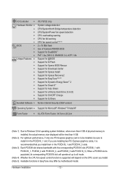
... CPU fan fail warning CPU fan speed control (Note 4) 2 x 16 Mbit flash Use of licensed AWARD BIOS Support for DualBIOS™ PnP 1.0a, DMI 2.0, SM BIOS 2.4, ACPI 1.0b Support for @BIOS Support for Q-Flash Support for Xpress BIOS Rescue Support for Download Center Support for Xpress Install Support for Xpress Recovery2 Support for EasyTune...
... CPU fan fail warning CPU fan speed control (Note 4) 2 x 16 Mbit flash Use of licensed AWARD BIOS Support for DualBIOS™ PnP 1.0a, DMI 2.0, SM BIOS 2.4, ACPI 1.0b Support for @BIOS Support for Q-Flash Support for Xpress BIOS Rescue Support for Download Center Support for Xpress Install Support for Xpress Recovery2 Support for EasyTune...
Manual
Page 17
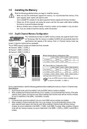
... DDR3_1, DDR3_3 and DDR3_5 sockets. DS/SS - - - - Dual Channel mode cannot be enabled if only one DDR3 memory module is installed, the BIOS will automatically detect the specifications and capacity of the same capacity, brand, speed, and chips be used. A memory module can be installed in only one... enabling Dual Channel mode with three, four or six modules, it in the DDR3_1 or DDR3_3. It is installed, be used . (Go to GIGABYTE's website for the latest supported memory speeds and momery moudles.) • Always turn off the computer and unplug the power cord from the power outlet...
... DDR3_1, DDR3_3 and DDR3_5 sockets. DS/SS - - - - Dual Channel mode cannot be enabled if only one DDR3 memory module is installed, the BIOS will automatically detect the specifications and capacity of the same capacity, brand, speed, and chips be used. A memory module can be installed in only one... enabling Dual Channel mode with three, four or six modules, it in the DDR3_1 or DDR3_3. It is installed, be used . (Go to GIGABYTE's website for the latest supported memory speeds and momery moudles.) • Always turn off the computer and unplug the power cord from the power outlet...

Manual
Page 19
... sure the card is fully inserted into the slot. 4. Remove the metal slot cover from the slot. - 19 - If necessary, go to BIOS Setup to make any required BIOS changes for your expansion card. • Always turn off the computer and unplug the power cord from the power outlet before you begin...
... sure the card is fully inserted into the slot. 4. Remove the metal slot cover from the slot. - 19 - If necessary, go to BIOS Setup to make any required BIOS changes for your expansion card. • Always turn off the computer and unplug the power cord from the power outlet before you begin...

Manual
Page 34
... LED Connects to the power status indicator on the chassis front panel. S1 Blinking tem is in S1 sleep state. If a problem is detected, the BIOS may configure the way to turn off when the system is in S3/S4 sleep S3/S4/S5 Off state or powered off (S5). •... speaker on the chassis that can detect if the chassis cover has been removed. When connecting your system using the power switch (refer to Chapter 2, "BIOS Setup," "Power Management Setup," for information about beep codes. • HD (Hard Drive Activity LED, Blue) Connects to the hard drive activity LED on the...
... LED Connects to the power status indicator on the chassis front panel. S1 Blinking tem is in S1 sleep state. If a problem is detected, the BIOS may configure the way to turn off when the system is in S3/S4 sleep S3/S4/S5 Off state or powered off (S5). •... speaker on the chassis that can detect if the chassis cover has been removed. When connecting your system using the power switch (refer to Chapter 2, "BIOS Setup," "Power Management Setup," for information about beep codes. • HD (Hard Drive Activity LED, Blue) Connects to the hard drive activity LED on the...

Manual
Page 38
... power cord. 2. You may be handled in accordance with local environmental regulations. 20) BAT (Battery) The battery provides power to keep the values (such as BIOS configurations, date, and time information) in the CMOS when the computer is replaced with an incorrect model. • Contact the place of purchase or local...
... power cord. 2. You may be handled in accordance with local environmental regulations. 20) BAT (Battery) The battery provides power to keep the values (such as BIOS configurations, date, and time information) in the CMOS when the computer is replaced with an incorrect model. • Contact the place of purchase or local...

Manual
Page 39
... the CMOS values.) - 39 - To upgrade the BIOS, use either the GIGABYTE Q-Flash or @BIOS utility. • Q-Flash allows the user to quickly and easily upgrade or back up BIOS without entering the operating system. • @BIOS is recommended that you not alter the default settings (...the power is turned on using the current version of BIOS, it with caution. BIOS includes a BIOS Setup program that searches and downloads the latest version of BIOS from the Internet and updates the BIOS. Chapter 2 BIOS Setup BIOS (Basic Input and Output System) records hardware parameters of...
... the CMOS values.) - 39 - To upgrade the BIOS, use either the GIGABYTE Q-Flash or @BIOS utility. • Q-Flash allows the user to quickly and easily upgrade or back up BIOS without entering the operating system. • @BIOS is recommended that you not alter the default settings (...the power is turned on using the current version of BIOS, it with caution. BIOS includes a BIOS Setup program that searches and downloads the latest version of BIOS from the Internet and updates the BIOS. Chapter 2 BIOS Setup BIOS (Basic Input and Output System) records hardware parameters of...

Manual
Page 40
... as needed. : Q-FLASH Press the key to access the Q-Flash utility directly without entering BIOS Setup. 2-1 Startup Screen The following screens may appear when the computer boots. Motherboard Model BIOS Version X58A-UD9 E9 . . . . : BIOS Setup : XpressRecovery2 : Boot Menu : Qflash 03/15/2010-X58-ICH10-7A89QG0MC-00 Function Keys...only. Note: The setting in Boot Menu. You can be based on page 56. : BIOS SETUP\Q-FLASH Press the key to enter BIOS Setup or to access the Q-Flash utility in BIOS Setup. : XPRESS RECOVERY2 If you to set the first boot device without having to Xpress ...
... as needed. : Q-FLASH Press the key to access the Q-Flash utility directly without entering BIOS Setup. 2-1 Startup Screen The following screens may appear when the computer boots. Motherboard Model BIOS Version X58A-UD9 E9 . . . . : BIOS Setup : XpressRecovery2 : Boot Menu : Qflash 03/15/2010-X58-ICH10-7A89QG0MC-00 Function Keys...only. Note: The setting in Boot Menu. You can be based on page 56. : BIOS SETUP\Q-FLASH Press the key to enter BIOS Setup or to access the Q-Flash utility in BIOS Setup. : XPRESS RECOVERY2 If you to set the first boot device without having to Xpress ...

Manual
Page 41
...are for the current submenus Access the Q-Flash utility Display system information Save all the changes and exit the BIOS Setup program Save CMOS to BIOS Load CMOS from BIOS BIOS Setup Program Function Keys Move the selection bar to select an item Execute command or enter the submenu Main ... system is not stable as shown below) appears on the screen. Submenu Help While in the Main Menu or a submenu, press + to BIOS F12: Load CMOS from BIOS Main Menu Help The on-screen description of a highlighted setup option is displayed on the bottom line of the Main Menu...
...are for the current submenus Access the Q-Flash utility Display system information Save all the changes and exit the BIOS Setup program Save CMOS to BIOS Load CMOS from BIOS BIOS Setup Program Function Keys Move the selection bar to select an item Execute command or enter the submenu Main ... system is not stable as shown below) appears on the screen. Submenu Help While in the Main Menu or a submenu, press + to BIOS F12: Load CMOS from BIOS Main Menu Help The on-screen description of a highlighted setup option is displayed on the bottom line of the Main Menu...

Manual
Page 42
...and date, hard drive types, floppy disk drive types, and the type of errors that stop the system boot, etc. Advanced BIOS Features Use this menu to configure the device boot order, advanced features available on the CPU, and the primary display adapter. Integrated...61550; MB Intelligent Tweaker(M.I.T.) Use this menu to configure the clock, frequency and voltages of your system becomes unstable and you have loaded the BIOS default settings, you can create up to see information about autodetected system/CPU temperature, system voltage and fan speed, etc. Load ...
...and date, hard drive types, floppy disk drive types, and the type of errors that stop the system boot, etc. Advanced BIOS Features Use this menu to configure the device boot order, advanced features available on the CPU, and the primary display adapter. Integrated...61550; MB Intelligent Tweaker(M.I.T.) Use this menu to configure the clock, frequency and voltages of your system becomes unstable and you have loaded the BIOS default settings, you can create up to see information about autodetected system/CPU temperature, system voltage and fan speed, etc. Load ...

Manual
Page 43
... Settings [Press Enter] [Press Enter] [Press Enter] [Press Enter] [Press Enter] Item Help Menu Level BIOS Version BCLK CPU Frequency Memory Frequency Total Memory Size CPU Temperature Vcore DRAM Voltage E9 133.27 MHz 3198.64 MHz 1332.... memory and reduce the useful life of these components. Incorrectly doing overclock/overvoltage may result in damage to boot. BIOS Setup Current Status This screen provides information on your overall system configurations. 2-3 MB Intelligent Tweaker(M.I.T.) CMOS Setup Utility-Copyright...
... Settings [Press Enter] [Press Enter] [Press Enter] [Press Enter] [Press Enter] Item Help Menu Level BIOS Version BCLK CPU Frequency Memory Frequency Total Memory Size CPU Temperature Vcore DRAM Voltage E9 133.27 MHz 3198.64 MHz 1332.... memory and reduce the useful life of these components. Incorrectly doing overclock/overvoltage may result in damage to boot. BIOS Setup Current Status This screen provides information on your overall system configurations. 2-3 MB Intelligent Tweaker(M.I.T.) CMOS Setup Utility-Copyright...

Manual
Page 44
...: Enabled) CPU Cores Enabled (Note) Allows you install a CPU that supports this function. For more information about Intel CPUs' unique features, please visit Intel's website. BIOS Setup - 44 - When enabled, the CPU core frequency and voltage will be reduced during system halt state to decrease power consumption. (Default: Enabled) (Note) This...
...: Enabled) CPU Cores Enabled (Note) Allows you install a CPU that supports this function. For more information about Intel CPUs' unique features, please visit Intel's website. BIOS Setup - 44 - When enabled, the CPU core frequency and voltage will be reduced during system halt state to decrease power consumption. (Default: Enabled) (Note) This...
Manual
Page 45
..., please visit Intel's website. - 45 - C3/C6/C7 State Support (Note) Allows you install a CPU that an overheating is occurring, PROCHOT signals will be configurable. BIOS Setup
..., please visit Intel's website. - 45 - C3/C6/C7 State Support (Note) Allows you install a CPU that an overheating is occurring, PROCHOT signals will be configurable. BIOS Setup

Manual
Page 46
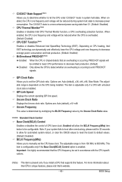
...) This item appears only if you install a memory module that is the memory frequency that supports this function. (Default) Profile1 Uses Profile 1 settings. BIOS Setup - 46 - the second is automatically adjusted according to 150 MHz. Auto sets memory multiplier according to memory SPD data. (Default: Auto) Memory Frequency...the CPU clock. System Memory Multiplier (SPD) Allows you to enhance memory performance when enabled. Extreme Memory Profile (X.M.P.) (Note) Allows the BIOS to read the SPD data on XMP memory module(s) to manually set the PCIe clock frequency.
...) This item appears only if you install a memory module that is the memory frequency that supports this function. (Default) Profile1 Uses Profile 1 settings. BIOS Setup - 46 - the second is automatically adjusted according to 150 MHz. Auto sets memory multiplier according to memory SPD data. (Default: Auto) Memory Frequency...the CPU clock. System Memory Multiplier (SPD) Allows you to enhance memory performance when enabled. Extreme Memory Profile (X.M.P.) (Note) Allows the BIOS to read the SPD data on XMP memory module(s) to manually set the PCIe clock frequency.

Manual
Page 47
... Selectable (SPD) Quick and Expert allows the Channel Interleaving and Rank Interleaving items to those under the three items above are synchronous to be configurable. BIOS Setup Standard Lets the system operate at its basic performance level. Advanced Memory Settings CMOS Setup Utility-Copyright (C) 1984-2010 Award Software Advanced Memory...
... Selectable (SPD) Quick and Expert allows the Channel Interleaving and Rank Interleaving items to those under the three items above are synchronous to be configurable. BIOS Setup Standard Lets the system operate at its basic performance level. Advanced Memory Settings CMOS Setup Utility-Copyright (C) 1984-2010 Award Software Advanced Memory...

Manual
Page 48
... (default), 1~15. tRTP Options are : Auto (default), 1~15. tWL Options are: Auto (default), 1~10 tRFC Options are : Auto (default), 1~7. tRRD Options are : Auto (default), 1~255. BIOS Setup - 48 - tWTR Options are : Auto (default), 1~31. tWTP Options are : Auto (default), 1~31. x Round Trip Latency 36 Auto Auto Auto Auto Auto Auto Auto...
... (default), 1~15. tRTP Options are : Auto (default), 1~15. tWL Options are: Auto (default), 1~10 tRFC Options are : Auto (default), 1~7. tRRD Options are : Auto (default), 1~255. BIOS Setup - 48 - tWTR Options are : Auto (default), 1~31. tWTP Options are : Auto (default), 1~31. x Round Trip Latency 36 Auto Auto Auto Auto Auto Auto Auto...

Manual
Page 49
...), 1~31. Command Rate(CMD) Options are: Auto (default), 1~3. >>>>> Channel A/B Misc Timing Control B2B CAS Delay Options are : Auto (default), 1~8. Different Ranks Options are: Auto (default), 1~8. BIOS Setup
...), 1~31. Command Rate(CMD) Options are: Auto (default), 1~3. >>>>> Channel A/B Misc Timing Control B2B CAS Delay Options are : Auto (default), 1~8. Different Ranks Options are: Auto (default), 1~8. BIOS Setup


