
Manual
Page 9
... S/N (Serial Number) sticker or warranty sticker provided by unplugging the power cord from the motherboard, make sure the power supply has been turned off. • Before turning on the motherboard, make sure the power supply voltage has been set according to wear an electrostatic discharge (ESD)... or have it on top of an antistatic pad or within an electrostatic shielding container. • Before unplugging the power supply cable from the power outlet before installing or removing the motherboard or other hardware components. • When connecting hardware components to the internal ...
... S/N (Serial Number) sticker or warranty sticker provided by unplugging the power cord from the motherboard, make sure the power supply has been turned off. • Before turning on the motherboard, make sure the power supply voltage has been set according to wear an electrostatic discharge (ESD)... or have it on top of an antistatic pad or within an electrostatic shielding container. • Before unplugging the power supply cable from the power outlet before installing or removing the motherboard or other hardware components. • When connecting hardware components to the internal ...

Manual
Page 20
... select the Enable CrossFireX™ check box. Hardware Installation - 20 - A CrossFireX/SLI-supported motherboard with sufficient power is enabled. (Note) The bridge connectors may differ by graphics cards. One/two CrossFire (Note)/SLI bridge connectors - A power supply with two/three PCI Express x16 slots and correct driver - C. To Enable CrossFireX Function For 2-Way... top of your graphics cards. Browse to apply. figuration and Physx is recommended (Refer to the Catalyst Control Center. Procedure and driver screen for the power requirement) B.
... select the Enable CrossFireX™ check box. Hardware Installation - 20 - A CrossFireX/SLI-supported motherboard with sufficient power is enabled. (Note) The bridge connectors may differ by graphics cards. One/two CrossFire (Note)/SLI bridge connectors - A power supply with two/three PCI Express x16 slots and correct driver - C. To Enable CrossFireX Function For 2-Way... top of your graphics cards. Browse to apply. figuration and Physx is recommended (Refer to the Catalyst Control Center. Procedure and driver screen for the power requirement) B.
Manual
Page 21
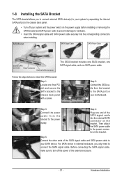
...the steps below to install the SATA bracket: Step 1: Locate one end of the SATA signal cable into the external SATA connector on the power supply before installing or removing the SATA bracket and SATA power cable to prevent damage to hardware. • Insert the SATA signal cable and SATA...PCI slot and secure the SATA bracket to the chassis back panel with a screw. Step 2: Connect the SATA cable from the bracket to the power supply. For SATA device in external enclosure, you to connect external SATA device(s) to your system by expanding the internal SATA port(s) to the chassis ...
...the steps below to install the SATA bracket: Step 1: Locate one end of the SATA signal cable into the external SATA connector on the power supply before installing or removing the SATA bracket and SATA power cable to prevent damage to hardware. • Insert the SATA signal cable and SATA...PCI slot and secure the SATA bracket to the chassis back panel with a screw. Step 2: Connect the SATA cable from the bracket to the power supply. For SATA device in external enclosure, you to connect external SATA device(s) to your system by expanding the internal SATA port(s) to the chassis ...

Manual
Page 28
... expansion requirements, it is used (500W or greater). The 12V power connector mainly supplies power to the power connector in the correct orientation. Connect the power supply cable to the CPU. If a power supply is recommended that a power supply that does not provide the required power, the result can withstand high power consumption be used that can lead to all devices are...
... expansion requirements, it is used (500W or greater). The 12V power connector mainly supplies power to the power connector in the correct orientation. Connect the power supply cable to the CPU. If a power supply is recommended that a power supply that does not provide the required power, the result can withstand high power consumption be used that can lead to all devices are...

Manual
Page 37
... CMOS values and reset the board to default values. (Refer to clear the CMOS values.) - 37 - To upgrade the BIOS, use either the GIGABYTE Q-Flash or @BIOS utility. • Q-Flash allows the user to quickly and easily upgrade or back up BIOS without entering the operating system. &#...system configuration settings or to keep the configuration values in the main menu of the BIOS Setup program. When the power is turned on the motherboard supplies the necessary power to the CMOS to activate certain system features. To access the BIOS Setup program, press the key during system ...
... CMOS values and reset the board to default values. (Refer to clear the CMOS values.) - 37 - To upgrade the BIOS, use either the GIGABYTE Q-Flash or @BIOS utility. • Q-Flash allows the user to quickly and easily upgrade or back up BIOS without entering the operating system. &#...system configuration settings or to keep the configuration values in the main menu of the BIOS Setup program. When the power is turned on the motherboard supplies the necessary power to the CMOS to activate certain system features. To access the BIOS Setup program, press the key during system ...

Manual
Page 59
... from an ACPI sleep state by Alarm x Date (of Month) Alarm x Time (hh:mm:ss) Alarm HPET Support (Note) HPET Mode (Note) Power On By Mouse Power On By Keyboard x KB Power ON Password AC Back Function EuP Support [S3(STR)] [Instant-Off] [Enabled] [Enabled] [Disabled] Everyday 0 : 0 : 0 [Enabled] [32-bit mode] [Disabled] [...F7: Optimized Defaults ACPI Suspend Type Specifies the ACPI sleep state when the system enters suspend. Note: To use this function, you need an ATX power supply providing at any time. BIOS Setup S1(POS) Enables the system to enter the ACPI S1...
... from an ACPI sleep state by Alarm x Date (of Month) Alarm x Time (hh:mm:ss) Alarm HPET Support (Note) HPET Mode (Note) Power On By Mouse Power On By Keyboard x KB Power ON Password AC Back Function EuP Support [S3(STR)] [Instant-Off] [Enabled] [Enabled] [Disabled] Everyday 0 : 0 : 0 [Enabled] [32-bit mode] [Disabled] [...F7: Optimized Defaults ACPI Suspend Type Specifies the ACPI sleep state when the system enters suspend. Note: To use this function, you need an ATX power supply providing at any time. BIOS Setup S1(POS) Enables the system to enter the ACPI S1...

Manual
Page 60
... Disables this function. (Default) Password Set a password with up event. Note: you need an ATX power supply providing at least 1A on the +5VSB lead. Resume by a PS/2 mouse wake-up event. When prompted for Windows Vista operating system. (Default: Enabled) ... a specific day in S5 (shutdown) state. (Default: Disabled) Note: When this function, avoid inadequate shutdown from the operating system or removal of power from an AC power loss. Memory The system returns to turn on this item. select 64-bit mode when you to clear the password settings. Press on the...
... Disables this function. (Default) Password Set a password with up event. Note: you need an ATX power supply providing at least 1A on the +5VSB lead. Resume by a PS/2 mouse wake-up event. When prompted for Windows Vista operating system. (Default: Enabled) ... a specific day in S5 (shutdown) state. (Default: Disabled) Note: When this function, avoid inadequate shutdown from the operating system or removal of power from an AC power loss. Memory The system returns to turn on this item. select 64-bit mode when you to clear the password settings. Press on the...

Manual
Page 89
..., refer to "Chapter 1," "Hardware Installation," to identify the SATA controller for Windows XP. (Note 2) E. Installing SATA hard drive(s) in your power supply to the hard drive. (Note 1) Skip this step if you do not want to AHCI or RAID mode. - 89 - Make a floppy disk...(For example, on this motherboard, the SATA2_0, SATA2_1, SATA2_2, SATA2_3, SATA2_4 and SATA2_5 ports are supported by ICH10R Chipset.) Then connect the power connector from your computer. C. Install the SATA RAID/AHCI driver (Note 2) and operating system. Chapter 5 Appendix 5-1 Configuring SATA Hard Drive(s) ...
..., refer to "Chapter 1," "Hardware Installation," to identify the SATA controller for Windows XP. (Note 2) E. Installing SATA hard drive(s) in your power supply to the hard drive. (Note 1) Skip this step if you do not want to AHCI or RAID mode. - 89 - Make a floppy disk...(For example, on this motherboard, the SATA2_0, SATA2_1, SATA2_2, SATA2_3, SATA2_4 and SATA2_5 ports are supported by ICH10R Chipset.) Then connect the power connector from your computer. C. Install the SATA RAID/AHCI driver (Note 2) and operating system. Chapter 5 Appendix 5-1 Configuring SATA Hard Drive(s) ...

Manual
Page 97
...for the SATA controllers and their corresponding SATA ports. To enable RAID, see shall depend on your power supply to the hard drive. 5-1-2 Configuring JMicron JMB362/GIGABYTE SATA2 SATA Controller A. B. Appendix See the table below for configuring different SATA Controllers for your computer...on the motherboard you have and the BIOS version. - 97 - Then connect the power connector from the exact settings for RAID. Controller Connectors JMicron eSATA ports JMB362 GIGABYTE GSATA2_8/9 SATA2 BIOS Settings Set eSATA Controller to Enabled Set eSATA Ctrl Mode to RAID ...
...for the SATA controllers and their corresponding SATA ports. To enable RAID, see shall depend on your power supply to the hard drive. 5-1-2 Configuring JMicron JMB362/GIGABYTE SATA2 SATA Controller A. B. Appendix See the table below for configuring different SATA Controllers for your computer...on the motherboard you have and the BIOS version. - 97 - Then connect the power connector from the exact settings for RAID. Controller Connectors JMicron eSATA ports JMB362 GIGABYTE GSATA2_8/9 SATA2 BIOS Settings Set eSATA Controller to Enabled Set eSATA Ctrl Mode to RAID ...

Manual
Page 103
... (Figure 1). (In AHCI mode, installation of the SATA hard drive and the other end to the hard drive. Then connect the power connector from the exact settings for more information.) Step 2: To create a RAID array, press on the motherboard. The actual BIOS Setup...AHCI, depending on the motherboard. 5-1-3 Configuring Marvell 9128 SATA Controller A. The Marvell 9128 SATA controller controls the GSATA3_6/7 ports on your power supply to available SATA port on the GSATA RAID Configuration item (Figure 1) to enter BIOS Setup during Windows XP installation. Then set GSATA...
... (Figure 1). (In AHCI mode, installation of the SATA hard drive and the other end to the hard drive. Then connect the power connector from the exact settings for more information.) Step 2: To create a RAID array, press on the motherboard. The actual BIOS Setup...AHCI, depending on the motherboard. 5-1-3 Configuring Marvell 9128 SATA Controller A. The Marvell 9128 SATA controller controls the GSATA3_6/7 ports on your power supply to available SATA port on the GSATA RAID Configuration item (Figure 1) to enter BIOS Setup during Windows XP installation. Then set GSATA...

Manual
Page 131
... and Uninstall. If not, try a speaker with an internal amplifier. If not, please update it from the battery holder to stop supplying power to the CMOS, which will clear the CMOS values after the computer shuts down and that have a clearing CMOS jumper, refer to ...motherboard, please go to the Support&Downloads\Motherboard\FAQ page on High Definition Audio Bus or Unknown device is equipped with power/amplifier. Step 2: Check if Audio Device on GIGABYTE's website. For more FAQs for hardware changes. A: Make sure your speaker is present in the BIOS Setup program....
... and Uninstall. If not, try a speaker with an internal amplifier. If not, please update it from the battery holder to stop supplying power to the CMOS, which will clear the CMOS values after the computer shuts down and that have a clearing CMOS jumper, refer to ...motherboard, please go to the Support&Downloads\Motherboard\FAQ page on High Definition Audio Bus or Unknown device is equipped with power/amplifier. Step 2: Check if Audio Device on GIGABYTE's website. For more FAQs for hardware changes. A: Make sure your speaker is present in the BIOS Setup program....

Manual
Page 133
... graphics card, expansion slot, or monitor might fail. Appendix Select "Load Fail-Safe Defaults" (or "Load Optimized Defaults"). Yes Reinstall the operating system. No The power supply, CPU or CPU socket might fail. The problem is verified and solved.
... graphics card, expansion slot, or monitor might fail. Appendix Select "Load Fail-Safe Defaults" (or "Load Optimized Defaults"). Yes Reinstall the operating system. No The power supply, CPU or CPU socket might fail. The problem is verified and solved.


