Manual
Page 7
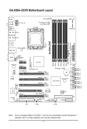
... LGA1366 FREQ. For a longer expansion card, use other expansion slots. - 7 - LED PHASE LED DDR Voltage LED PWR_FAN GA-X58A-UD3R R_USB ATX USB30_LAN JMicron JMB362 DDR3_4 DDR3_3 DDR3_6 DDR3_5 NB PHASE LED DDR PHASE LED F_AUDIO NB TEMP L1/2 AUDIO NEC D720200F1 PCIEX1_1...® ICH10R Marvell 9128 SYS_FAN3 TSB43AB23 SYS_FAN2 F_USB2 GIGABYTE SATA2 F_PANEL SATA2_1 SATA2_0 SATA2_3 SATA2_2 SATA2_5 SATA2_4 GSATA3_7 GSATA3_6 GSATA2_9 GSATA2_8 IDE FDD F_1394 F_USB1 (Note) Due to a hardware limitation, the PCIEX1_1 slot can only accommodate a shorter PCI Express x1 expansion card.
... LGA1366 FREQ. For a longer expansion card, use other expansion slots. - 7 - LED PHASE LED DDR Voltage LED PWR_FAN GA-X58A-UD3R R_USB ATX USB30_LAN JMicron JMB362 DDR3_4 DDR3_3 DDR3_6 DDR3_5 NB PHASE LED DDR PHASE LED F_AUDIO NB TEMP L1/2 AUDIO NEC D720200F1 PCIEX1_1...® ICH10R Marvell 9128 SYS_FAN3 TSB43AB23 SYS_FAN2 F_USB2 GIGABYTE SATA2 F_PANEL SATA2_1 SATA2_0 SATA2_3 SATA2_2 SATA2_5 SATA2_4 GSATA3_7 GSATA3_6 GSATA2_9 GSATA2_8 IDE FDD F_1394 F_USB1 (Note) Due to a hardware limitation, the PCIEX1_1 slot can only accommodate a shorter PCI Express x1 expansion card.
Manual
Page 8
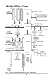
GA-X58A-UD3R Block Diagram 2 PCI Express x16 4 PCI Express x8 PCIe CLK (100 MHz) or LGA1366 CPU CPU CLK+/- (133 MHz) DDR3 2200/1333/1066/800 MHz Dual/3 Channel Memory QPI x16 x8 PCI Express Bus PCIe CLK (100 MHz) Switch LAN RJ45 RTL8111D Interface Intel® X58 IOH CLK (133 MHz) PCI Express Bus ...x1 x1 x1 (100 MHz) JMicron JMB362 Intel® ICH10R 2 PCI Express x1 x1 2 eSATA 3Gb/s 2 SATA 6Gb/s 2 USB 3.0 Dual BIOS 6 SATA 3Gb/s 12 USB 2.0/1.1 (Note) 2 SATA 3Gb/s ATA-133/100/66/33 IDE Channel GIGABYTE SATA2 PCI Bus TSB43AB23 CODEC LPC Bus IT8720 Floppy PS/2 KB/Mouse 3 ...
GA-X58A-UD3R Block Diagram 2 PCI Express x16 4 PCI Express x8 PCIe CLK (100 MHz) or LGA1366 CPU CPU CLK+/- (133 MHz) DDR3 2200/1333/1066/800 MHz Dual/3 Channel Memory QPI x16 x8 PCI Express Bus PCIe CLK (100 MHz) Switch LAN RJ45 RTL8111D Interface Intel® X58 IOH CLK (133 MHz) PCI Express Bus ...x1 x1 x1 (100 MHz) JMicron JMB362 Intel® ICH10R 2 PCI Express x1 x1 2 eSATA 3Gb/s 2 SATA 6Gb/s 2 USB 3.0 Dual BIOS 6 SATA 3Gb/s 12 USB 2.0/1.1 (Note) 2 SATA 3Gb/s ATA-133/100/66/33 IDE Channel GIGABYTE SATA2 PCI Bus TSB43AB23 CODEC LPC Bus IT8720 Floppy PS/2 KB/Mouse 3 ...
Manual
Page 10
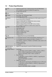
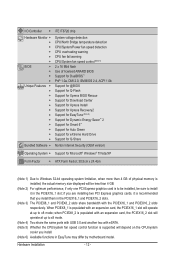
... to GIGABYTE's website for the latest memory support list.) Realtek ALC889 codec High Definition Audio 2/4/5.1/7.1-channel Support for Dolby® Home Theater Support for S/PDIF In/Out Support for CD In LAN 1 x Realtek RTL8111D chip (10/100/1000 Mbit) Expansion Slots 2 x PCI Express x16 slots...
... to GIGABYTE's website for the latest memory support list.) Realtek ALC889 codec High Definition Audio 2/4/5.1/7.1-channel Support for Dolby® Home Theater Support for S/PDIF In/Out Support for CD In LAN 1 x Realtek RTL8111D chip (10/100/1000 Mbit) Expansion Slots 2 x PCI Express x16 slots...
Manual
Page 12
if you are installing two PCI Express graphics cards, it in the PCIEX16_1 and PCIEX16_2 slots. (Note 3) The PCIEX8_1 and PCIEX8_2 slots share bandwidth with the PCIEX16_1 and PCIEX16_2 slots respectively. Hardware ... Factor; 30.5cm x 24.4cm (Note 1) Due to Windows 32-bit operating system limitation, when more than 4 GB. (Note 2) For optimum performance, if only one PCI Express graphics card is to be installed, be sure to x8 mode; when PCIEX8_2 is populated with an expansion card, the PCIEX16_2 slot will operate at...
if you are installing two PCI Express graphics cards, it in the PCIEX16_1 and PCIEX16_2 slots. (Note 3) The PCIEX8_1 and PCIEX8_2 slots share bandwidth with the PCIEX16_1 and PCIEX16_2 slots respectively. Hardware ... Factor; 30.5cm x 24.4cm (Note 1) Due to Windows 32-bit operating system limitation, when more than 4 GB. (Note 2) For optimum performance, if only one PCI Express graphics card is to be installed, be sure to x8 mode; when PCIEX8_2 is populated with an expansion card, the PCIEX16_2 slot will operate at...
Manual
Page 18
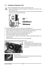
...to BIOS Setup to correctly install your expansion card in your operating system. Locate an expansion slot that came with a screw. 5. PCI Express x1 Slot PCI Express x16 Slot PCI Slot Follow the steps below to make any required BIOS changes for your computer. Turn on the card are completely inserted into the... PCI Express slot. Install the driver provided with the slot, and press down on the card until it is securely seated in the slot. 3. ...
...to BIOS Setup to correctly install your expansion card in your operating system. Locate an expansion slot that came with a screw. 5. PCI Express x1 Slot PCI Express x16 Slot PCI Slot Follow the steps below to make any required BIOS changes for your computer. Turn on the card are completely inserted into the... PCI Express slot. Install the driver provided with the slot, and press down on the card until it is securely seated in the slot. 3. ...
Manual
Page 19
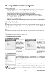
...Connecting the Graphics Cards Step 1: Observe the steps in "1-5 Installing an Expansion Card" and install two/three CrossFireX/SLI graphics cards on the PCI Express x16 slots. (To set up a 2-Way configuration, we recommend installing the graphics cards on the PCIEX16_1 and PCIEX16_2 slots.) Step 2: Insert...Click OK to the CrossFireX menu and select the Enable CrossFireX™ check box. Browse to the manual that came with two/three PCI Express x16 slots and correct driver - C-2. 1-6 Setup of identical brand and chip and correct driver (Current ATI GPUs that support 3-Way ...
...Connecting the Graphics Cards Step 1: Observe the steps in "1-5 Installing an Expansion Card" and install two/three CrossFireX/SLI graphics cards on the PCI Express x16 slots. (To set up a 2-Way configuration, we recommend installing the graphics cards on the PCIEX16_1 and PCIEX16_2 slots.) Step 2: Insert...Click OK to the CrossFireX menu and select the Enable CrossFireX™ check box. Browse to the manual that came with two/three PCI Express x16 slots and correct driver - C-2. 1-6 Setup of identical brand and chip and correct driver (Current ATI GPUs that support 3-Way ...
Manual
Page 42
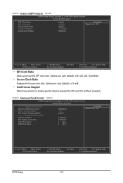
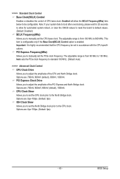
... ******** CMOS Setup Utility-Copyright (C) 1984-2009 Award Software Advanced Clock Control >>>>> Sandard Clock Control Base Clock(BCLK) Control x BCLK Frequency(Mhz) PCI Express Frequency(Mhz) >>>>> Advanced Clock Control CPU Clock Drive PCI Express Clock Drive CPU Clock Skew IOH Clock Skew [Disabled] 133 [Auto] [ 800mV] [ 900mV] [ 0ps] [ 0ps] Item Help Menu Level ...
... ******** CMOS Setup Utility-Copyright (C) 1984-2009 Award Software Advanced Clock Control >>>>> Sandard Clock Control Base Clock(BCLK) Control x BCLK Frequency(Mhz) PCI Express Frequency(Mhz) >>>>> Advanced Clock Control CPU Clock Drive PCI Express Clock Drive CPU Clock Skew IOH Clock Skew [Disabled] 133 [Auto] [ 800mV] [ 900mV] [ 0ps] [ 0ps] Item Help Menu Level ...
Manual
Page 43
...to boot after overclocking, please wait for 20 seconds to allow the BCLK Frequency(Mhz) item below to adjust the amplitude of the PCI Express and North Bridge clock. The adjustable range is highly recommended that the CPU frequency be configurable. This item is configurable only if ...the Base Clock(BCLK) Control option is from 90 MHz to the CPU clock. PCI Express Frequency(Mhz) Allows you to 600 MHz. Options are : 700mV, 800mV, 900mV (default), 1000mV. BIOS Setup Enabled will allow for automated ...
...to boot after overclocking, please wait for 20 seconds to allow the BCLK Frequency(Mhz) item below to adjust the amplitude of the PCI Express and North Bridge clock. The adjustable range is highly recommended that the CPU frequency be configurable. This item is configurable only if ...the Base Clock(BCLK) Control option is from 90 MHz to the CPU clock. PCI Express Frequency(Mhz) Allows you to 600 MHz. Options are : 700mV, 800mV, 900mV (default), 1000mV. BIOS Setup Enabled will allow for automated ...

Manual
Page 52
... message. (Default: Enabled) Backup BIOS Image to HDD Allows the system to copy the BIOS image file to display the GIGABYTE Logo at system startup. Set this feature. PCIE x8-1 Sets the PCI Express graphics card on the PCIEX16_1 slot as Windows NT4.0. (Default: Disabled) No-Execute Memory Protect (Note) Enables or disables...
... message. (Default: Enabled) Backup BIOS Image to HDD Allows the system to copy the BIOS image file to display the GIGABYTE Logo at system startup. Set this feature. PCIE x8-1 Sets the PCI Express graphics card on the PCIEX16_1 slot as Windows NT4.0. (Default: Disabled) No-Execute Memory Protect (Note) Enables or disables...

Manual
Page 94
... POST memory test begins and before the operating system boot begins, look for a non-RAID configuration. GIGABYTE Technology Corp. Gigabyte Technology Corp. PCI Express to SATAII HOST Controller ROM v1.07.06 Copyright (C) 2005-2009 Gigabyte Technology Corp. (http://www.gigabyte.com) HDD0 : HDD1 : ST3120026AS ST3120026AS 120 GB 120 GB Non-RAID Non-RAID Press to...
... POST memory test begins and before the operating system boot begins, look for a non-RAID configuration. GIGABYTE Technology Corp. Gigabyte Technology Corp. PCI Express to SATAII HOST Controller ROM v1.07.06 Copyright (C) 2005-2009 Gigabyte Technology Corp. (http://www.gigabyte.com) HDD0 : HDD1 : ST3120026AS ST3120026AS 120 GB 120 GB Non-RAID Non-RAID Press to...


