Manual
Page 16
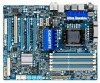
... them in the DDR3_1, DDR3_2, DDR3_3 and DDR3_5 sockets. • If only one direction. ory is installed, the BIOS will appear during the POST. DS/SS - - Dual Channel mode cannot be enabled if only one or two DDR3 memory modules are unable to install it is recommended that ... upgrade by allowing different memory sizes to install them in the DDR3_1 and DDR3_3 sockets. 3 Channel-1. 3 Channel mode cannot be used . (Go to GIGABYTE's website for the latest memory support list.) • Always turn off the computer and unplug the power cord from the power outlet before installing the...
... them in the DDR3_1, DDR3_2, DDR3_3 and DDR3_5 sockets. • If only one direction. ory is installed, the BIOS will appear during the POST. DS/SS - - Dual Channel mode cannot be enabled if only one or two DDR3 memory modules are unable to install it is recommended that ... upgrade by allowing different memory sizes to install them in the DDR3_1 and DDR3_3 sockets. 3 Channel-1. 3 Channel mode cannot be used . (Go to GIGABYTE's website for the latest memory support list.) • Always turn off the computer and unplug the power cord from the power outlet before installing the...
Manual
Page 35
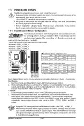
... it is turned off, the battery on the motherboard supplies the necessary power to the CMOS to boot. To upgrade the BIOS, use either the GIGABYTE Q-Flash or @BIOS utility. • Q-Flash allows the user to quickly and easily upgrade or back up BIOS without entering the operating system. •... program. Refer to Chapter 5, "Troubleshooting," for how to activate certain system features. To access the BIOS Setup program, press the key during the POST when the power is turned on using the current version of BIOS, it with caution. If this occurs, try to clear the CMOS values and...
... it is turned off, the battery on the motherboard supplies the necessary power to the CMOS to boot. To upgrade the BIOS, use either the GIGABYTE Q-Flash or @BIOS utility. • Q-Flash allows the user to quickly and easily upgrade or back up BIOS without entering the operating system. •... program. Refer to Chapter 5, "Troubleshooting," for how to activate certain system features. To access the BIOS Setup program, press the key during the POST when the power is turned on using the current version of BIOS, it with caution. If this occurs, try to clear the CMOS values and...
Manual
Page 36
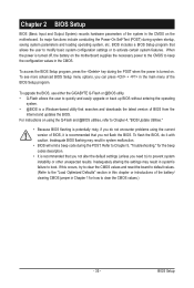
...Setup. : XPRESS RECOVERY2 If you to accept. To show the BIOS POST screen. The POST Screen Award Modular BIOS v6.00PG, An Energy Star Ally Copyright (C) 1984-2009, Award Software, Inc. BIOS Setup - 36 - Motherboard Model BIOS Version X58A-UD3R F1d . . . . : BIOS Setup : XpressRecovery2 : Boot ...Menu : Qflash 12/23/2009-X58-ICH10-7A89QG0KC-00 Function Keys Function Keys Function Keys: : POST SCREEN Press the key to show the BIOS POST screen at system startup, refer to the ...
...Setup. : XPRESS RECOVERY2 If you to accept. To show the BIOS POST screen. The POST Screen Award Modular BIOS v6.00PG, An Energy Star Ally Copyright (C) 1984-2009, Award Software, Inc. BIOS Setup - 36 - Motherboard Model BIOS Version X58A-UD3R F1d . . . . : BIOS Setup : XpressRecovery2 : Boot ...Menu : Qflash 12/23/2009-X58-ICH10-7A89QG0KC-00 Function Keys Function Keys Function Keys: : POST SCREEN Press the key to show the BIOS POST screen at system startup, refer to the ...

Manual
Page 49
... Configure your IDE/SATA devices by using one of the three methods below: • Auto Lets the BIOS automatically detect IDE/SATA devices during the POST. (Default) - 49 - The date format is 13:0:0. For example, 1 p.m. Time (hh:mm:ss) Sets the system time. Select the desired field and use the up...
... Configure your IDE/SATA devices by using one of the three methods below: • Auto Lets the BIOS automatically detect IDE/SATA devices during the POST. (Default) - 49 - The date format is 13:0:0. For example, 1 p.m. Time (hh:mm:ss) Sets the system time. Select the desired field and use the up...

Manual
Page 50
...all other errors. Typically, 640 KB will not stop for a floppy disk drive error but it will stop for an error during the POST. Options are : Auto (default), Large. Capacity Approximate capacity of sectors. Access Mode Sets the hard drive access mode. Access Mode Sets...; None If no IDE/SATA devices are used , set this item to None so the system will skip the detection of the device during the POST for faster system startup. IDE Channel 2, 3 Master, 4, 5, 6 Master/Slave, 7 Master, 9 Master/Slave Extended IDE Drive Configure your hard drive ...
...all other errors. Typically, 640 KB will not stop for a floppy disk drive error but it will stop for an error during the POST. Options are : Auto (default), Large. Capacity Approximate capacity of sectors. Access Mode Sets the hard drive access mode. Access Mode Sets...; None If no IDE/SATA devices are used , set this item to None so the system will skip the detection of the device during the POST for faster system startup. IDE Channel 2, 3 Master, 4, 5, 6 Master/Slave, 7 Master, 9 Master/Slave Extended IDE Drive Configure your hard drive ...

Manual
Page 52
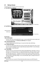
...first initiation of the monitor display from 0 to 15 seconds. (Default: 0) Full Screen LOGO Show Allows you to determine whether to display the GIGABYTE Logo at system startup. The ad- Set this feature. PCI Sets the PCI graphics card as the first display. (Default) PCIE x16-1 ... overflow attacks when working with its sup- set a delay time for the BIOS to Enabled for Windows XP operating system; Disabled displays normal POST message. (Default: Enabled) Backup BIOS Image to HDD Allows the system to copy the BIOS image file to limit CPUID maximum value. BIOS...
...first initiation of the monitor display from 0 to 15 seconds. (Default: 0) Full Screen LOGO Show Allows you to determine whether to display the GIGABYTE Logo at system startup. The ad- Set this feature. PCI Sets the PCI graphics card as the first display. (Default) PCIE x16-1 ... overflow attacks when working with its sup- set a delay time for the BIOS to Enabled for Windows XP operating system; Disabled displays normal POST message. (Default: Enabled) Backup BIOS Image to HDD Allows the system to copy the BIOS image file to limit CPUID maximum value. BIOS...
Manual
Page 54
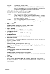
... in MS-DOS. (Default: Disabled) USB Storage Function Determines whether to detect USB storage devices, including USB flash drives and USB hard drives during the POST. (Default: Enabled) Azalia Codec Enables or disables the onboard audio function. (Default: Auto) If you wish to Disabled. Onboard H/W 1394 Enables or disables the onboard...
... in MS-DOS. (Default: Disabled) USB Storage Function Determines whether to detect USB storage devices, including USB flash drives and USB hard drives during the POST. (Default: Enabled) Azalia Codec Enables or disables the onboard audio function. (Default: Auto) If you wish to Disabled. Onboard H/W 1394 Enables or disables the onboard...
Manual
Page 70
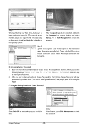
... Xpress Recovery2. 2. After you wish to start backing up your hard drive data. Step 1: Select BACKUP to enter Xpress Recovery2 later, simply press during the POST. Please note that if there is no enough unallocated space, Xpress Recovery2 cannot save the backup file to check disk allocation. If you use the...
... Xpress Recovery2. 2. After you wish to start backing up your hard drive data. Step 1: Select BACKUP to enter Xpress Recovery2 later, simply press during the POST. Please note that if there is no enough unallocated space, Xpress Recovery2 cannot save the backup file to check disk allocation. If you use the...
Manual
Page 72
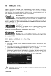
...file is DualBIOS™? X58A-UD3R F1d . . . . : BIOS Setup : XpressRecovery2 : Boot Menu : Qflash 12/23/2009-X58-ICH10-7A89QG0KC-00 Because BIOS flashing is @BIOS™? @BIOS allows you can access Q-Flash by adding one more physical BIOS chip. 4-2 BIOS Update Utilities GIGABYTE motherboards provide two unique ... it with the Q-Flash Utility A. Extract the file and save the new BIOS file (e.g. X58AUD3R.f1) to enter Q-Flash. During the POST, press the key to your floppy disk, USB flash drive, or hard drive. Motherboards that matches your computer by either pressing the key ...
...file is DualBIOS™? X58A-UD3R F1d . . . . : BIOS Setup : XpressRecovery2 : Boot Menu : Qflash 12/23/2009-X58-ICH10-7A89QG0KC-00 Because BIOS flashing is @BIOS™? @BIOS allows you can access Q-Flash by adding one more physical BIOS chip. 4-2 BIOS Update Utilities GIGABYTE motherboards provide two unique ... it with the Q-Flash Utility A. Extract the file and save the new BIOS file (e.g. X58AUD3R.f1) to enter Q-Flash. During the POST, press the key to your floppy disk, USB flash drive, or hard drive. Motherboards that matches your computer by either pressing the key ...
Manual
Page 73
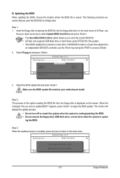
... from Drive Please SparevsesBaInOySketoy Dtoricvoentinue Enter : Run hi:Move ESC:Reset F10:Power Off - 73 - Step 2: The process of Q-Flash, use the key during the POST to update BIOS?" Unique Features The following procedure assumes that you sure to access Q-Flash. 2. Step 1: 1. Select Floppy A and press . appears, press to select Update...
... from Drive Please SparevsesBaInOySketoy Dtoricvoentinue Enter : Run hi:Move ESC:Reset F10:Power Off - 73 - Step 2: The process of Q-Flash, use the key during the POST to update BIOS?" Unique Features The following procedure assumes that you sure to access Q-Flash. 2. Step 1: 1. Select Floppy A and press . appears, press to select Update...
Manual
Page 74
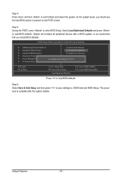
Step 5: During the POST, press to CMOS and exit BIOS Setup. System will re-detect all peripheral devices after the system restarts. CMOS Setup Utility-Copyright (C) 1984-2009 Award .... Unique Features - 74 - The procedure is complete after a BIOS update, so we recommend that you should see the new BIOS version is present on the POST screen. Select Load Optimized Defaults and press to exit Q-Flash and reboot the system. As the system boots, you reload BIOS defaults. Step 4: Press and...
Step 5: During the POST, press to CMOS and exit BIOS Setup. System will re-detect all peripheral devices after the system restarts. CMOS Setup Utility-Copyright (C) 1984-2009 Award .... Unique Features - 74 - The procedure is complete after a BIOS update, so we recommend that you should see the new BIOS version is present on the POST screen. Select Load Optimized Defaults and press to exit Q-Flash and reboot the system. As the system boots, you reload BIOS defaults. Step 4: Press and...
Manual
Page 86
... menu options you do not want to create RAID, set ICH SATA Control Mode under the Integrated Peripherals menu to enter BIOS Setup during the POST (Power-On Self-Test). Appendix - 86 - To create RAID, set this section may differ from the exact settings for your computer and press to RAID...
... menu options you do not want to create RAID, set ICH SATA Control Mode under the Integrated Peripherals menu to enter BIOS Setup during the POST (Power-On Self-Test). Appendix - 86 - To create RAID, set this section may differ from the exact settings for your computer and press to RAID...

Manual
Page 87
Step 1: After the POST memory test begins and before the operating system boot begins, look for a non-RAID configuration. RAID Volumes : None defined. Create RAID Volume If you press + , ...
Step 1: After the POST memory test begins and before the operating system boot begins, look for a non-RAID configuration. RAID Volumes : None defined. Create RAID Volume If you press + , ...
Manual
Page 93
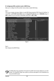
... Then connect the power connector from the exact settings for your power supply to the hard drive. Controller Connectors JMicron eSATA ports JMB362 GIGABYTE GSATA2_8/9 SATA2 BIOS Settings Set eSATA Controller to Enabled Set eSATA Ctrl Mode to RAID Set GSATA 8_9/IDE Controller to Enabled Set GSATA... of the SATA signal cable to the rear of the SATA hard drive and the other end to enter BIOS Setup during the POST. Appendix See the table below for configuring different SATA Controllers for the SATA controllers and their corresponding SATA ports. Configuring SATA controller ...
... Then connect the power connector from the exact settings for your power supply to the hard drive. Controller Connectors JMicron eSATA ports JMB362 GIGABYTE GSATA2_8/9 SATA2 BIOS Settings Set eSATA Controller to Enabled Set eSATA Ctrl Mode to RAID Set GSATA 8_9/IDE Controller to Enabled Set GSATA... of the SATA signal cable to the rear of the SATA hard drive and the other end to enter BIOS Setup during the POST. Appendix See the table below for configuring different SATA Controllers for the SATA controllers and their corresponding SATA ports. Configuring SATA controller ...

Manual
Page 94
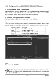
... Menu block. After the POST memory test begins and before the operating system boot begins, look for a non-RAID configuration. Press + to enter RAID Setup Utility ... PCI Express to SATAII HOST Controller ROM v1.07.06 Copyright (C) 2005-2009 Gigabyte Technology Corp. (http://www.gigabyte.com) HDD0 : HDD1 ... or down arrow key to highlight through choices in the Hard Disk Drive List block and press to configure a RAID array. GIGABYTE Technology Corp. Configuring a RAID array in RAID BIOS Enter the RAID BIOS setup utility to see detailed information about the selected hard drive....
... Menu block. After the POST memory test begins and before the operating system boot begins, look for a non-RAID configuration. Press + to enter RAID Setup Utility ... PCI Express to SATAII HOST Controller ROM v1.07.06 Copyright (C) 2005-2009 Gigabyte Technology Corp. (http://www.gigabyte.com) HDD0 : HDD1 ... or down arrow key to highlight through choices in the Hard Disk Drive List block and press to configure a RAID array. GIGABYTE Technology Corp. Configuring a RAID array in RAID BIOS Enter the RAID BIOS setup utility to see detailed information about the selected hard drive....
Manual
Page 99
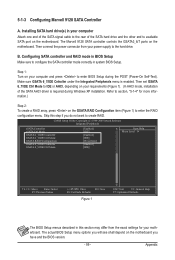
... configuration menu. Skip this section may differ from your motherboard. Make sure GSATA 6_7/IDE Cntroller under the Integrated Peripherals menu is required during the POST (Power-On Self-Test). CMOS Setup Utility-Copyright (C) 1984-2009 Award Software Integrated Peripherals eSATA Controller eSATA Ctrl Mode GSATA 6_7/IDE Controller GSATA 6_7...
... configuration menu. Skip this section may differ from your motherboard. Make sure GSATA 6_7/IDE Cntroller under the Integrated Peripherals menu is required during the POST (Power-On Self-Test). CMOS Setup Utility-Copyright (C) 1984-2009 Award Software Integrated Peripherals eSATA Controller eSATA Ctrl Mode GSATA 6_7/IDE Controller GSATA 6_7...

Manual
Page 127
... CMOS values after about one minute. Then install the onboard HD audio driver from the motherboard driver disk or download the audio driver from GIGABYTE's website to show the advanced options. Appendix If not, try a speaker with an internal amplifier. Step 2: Check if Audio Device on... inserted properly 1 long, 2 short: Monitor or graphics card error Continuous short beeps: Power error - 127 - Press to enter BIOS Setup during the POST mean? If your motherboard, please go to the Support&Downloads\Motherboard\FAQ page on . If yes, please disable this device. (If not, skip this...
... CMOS values after about one minute. Then install the onboard HD audio driver from the motherboard driver disk or download the audio driver from GIGABYTE's website to show the advanced options. Appendix If not, try a speaker with an internal amplifier. Step 2: Check if Audio Device on... inserted properly 1 long, 2 short: Monitor or graphics card error Continuous short beeps: Power error - 127 - Press to enter BIOS Setup during the POST mean? If your motherboard, please go to the Support&Downloads\Motherboard\FAQ page on . If yes, please disable this device. (If not, skip this...


