Manual
Page 2
Motherboard GA-X58A-OC Mar. 22, 2011 Motherboard GA-X58A-OC Mar. 22, 2011
Motherboard GA-X58A-OC Mar. 22, 2011 Motherboard GA-X58A-OC Mar. 22, 2011
Manual
Page 3
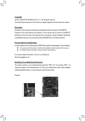
...by copyright laws and is the property of this product, GIGABYTE provides the following types of documentations: For quick set-up of the motherboard is protected by GIGABYTE without GIGABYTE's prior written permission. Documentation Classifications In order to the ...without prior notice. For product-related information, check on our website at: http://www.gigabyte.com Identifying Your Motherboard Revision The revision number on your motherboard revision before updating motherboard BIOS, drivers, or when looking for technical information. Example: Copyright © 2011...
...by copyright laws and is the property of this product, GIGABYTE provides the following types of documentations: For quick set-up of the motherboard is protected by GIGABYTE without GIGABYTE's prior written permission. Documentation Classifications In order to the ...without prior notice. For product-related information, check on our website at: http://www.gigabyte.com Identifying Your Motherboard Revision The revision number on your motherboard revision before updating motherboard BIOS, drivers, or when looking for technical information. Example: Copyright © 2011...
Manual
Page 4
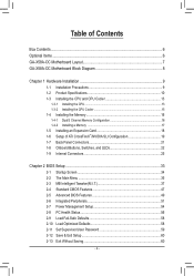
Table of Contents Box Contents...6 Optional Items...6 GA-X58A-OC Motherboard Layout 7 GA-X58A-OC Motherboard Block Diagram 8 Chapter 1 Hardware Installation 9 1-1 Installation Precautions 9 1-2 Product Specifications 10 1-3 Installing the CPU and CPU Cooler 13 1-3-1 Installing the CPU 13 1-3-2 Installing the CPU Cooler ...
Table of Contents Box Contents...6 Optional Items...6 GA-X58A-OC Motherboard Layout 7 GA-X58A-OC Motherboard Block Diagram 8 Chapter 1 Hardware Installation 9 1-1 Installation Precautions 9 1-2 Product Specifications 10 1-3 Installing the CPU and CPU Cooler 13 1-3-1 Installing the CPU 13 1-3-2 Installing the CPU Cooler ...
Manual
Page 6
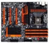
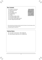
Box Contents GA-X58A-OC motherboard Motherboard driver disk User's Manual Quick Installation Guide Four SATA cables I/O Shield One 2-Way SLI bridge connector One 3-Way SLI bridge connector One 2-Way CrossFireX bridge connector Seven voltage measurement cables • The box contents above are subject to change without notice. • The motherboard image is for reference only and...
Box Contents GA-X58A-OC motherboard Motherboard driver disk User's Manual Quick Installation Guide Four SATA cables I/O Shield One 2-Way SLI bridge connector One 3-Way SLI bridge connector One 2-Way CrossFireX bridge connector Seven voltage measurement cables • The box contents above are subject to change without notice. • The motherboard image is for reference only and...
Manual
Page 7
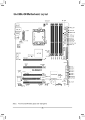
GA-X58A-OC Motherboard Layout CMOS_SW 4G Gear DIP 1 23 + _+ _ KB_MS USB_LAN AUDIO ATX_12V_2X1 R_USB3 ATX_12V_2X Realtek RTL8111E Etron EJ168 SW1 LGA1366 FREQ_DW FREQ_UP RATIO_DW SYS_FAN1 PW_SW ... DDR3_4 DDR3_3 DDR3_6 DDR3_5 Debug LED (Note) SYS_FAN6 SYS_FAN5 MCH Temperature Sensor PCIEX16_1 Intel® X58 CPU_FAN HP_PWR1 NB_FAN PCIEX8_1 SYS_FAN2 ATX4P4 CODEC GA-X58A-OC SYSTEM1 Temperature Sensor PCIEX16_2 iTE IT8720 PCI PCIEX8_2 F_AUDIO SYS_FAN4 SPDIF_O M_BIOS B_BIOS SYS_FAN3 Intel® ICH10R Marvell 88SE9182 MBIOS_LED BBIOS_LED F_USB1 SYSTEM2 Temperature ...
GA-X58A-OC Motherboard Layout CMOS_SW 4G Gear DIP 1 23 + _+ _ KB_MS USB_LAN AUDIO ATX_12V_2X1 R_USB3 ATX_12V_2X Realtek RTL8111E Etron EJ168 SW1 LGA1366 FREQ_DW FREQ_UP RATIO_DW SYS_FAN1 PW_SW ... DDR3_4 DDR3_3 DDR3_6 DDR3_5 Debug LED (Note) SYS_FAN6 SYS_FAN5 MCH Temperature Sensor PCIEX16_1 Intel® X58 CPU_FAN HP_PWR1 NB_FAN PCIEX8_1 SYS_FAN2 ATX4P4 CODEC GA-X58A-OC SYSTEM1 Temperature Sensor PCIEX16_2 iTE IT8720 PCI PCIEX8_2 F_AUDIO SYS_FAN4 SPDIF_O M_BIOS B_BIOS SYS_FAN3 Intel® ICH10R Marvell 88SE9182 MBIOS_LED BBIOS_LED F_USB1 SYSTEM2 Temperature ...
Manual
Page 8
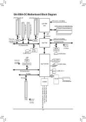
GA-X58A-OC Motherboard Block Diagram 2 PCI Express x8 2 PCI Express x8 LGA1366 CPU CPU CLK+/- (133 MHz) DDR3 2200/1333/1066/800 MHz Dual/3 Channel Memory 1 PCI Express ...
GA-X58A-OC Motherboard Block Diagram 2 PCI Express x8 2 PCI Express x8 LGA1366 CPU CPU CLK+/- (133 MHz) DDR3 2200/1333/1066/800 MHz Dual/3 Channel Memory 1 PCI Express ...
Manual
Page 9
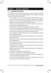
... and power connectors of the product, please consult a certified computer technician. - 9 - Chapter 1 Hardware Installation 1-1 Installation Precautions The motherboard contains numerous delicate electronic circuits and components which can lead to damage to system components as well as physical harm to the user. &#... wrist strap, keep your hands dry and first touch a metal object to eliminate static electricity. • Prior to installing the motherboard, please have a problem related to the use of your dealer. Prior to installation, carefully read the user's manual and follow these...
... and power connectors of the product, please consult a certified computer technician. - 9 - Chapter 1 Hardware Installation 1-1 Installation Precautions The motherboard contains numerous delicate electronic circuits and components which can lead to damage to system components as well as physical harm to the user. &#... wrist strap, keep your hands dry and first touch a metal object to eliminate static electricity. • Prior to installing the motherboard, please have a problem related to the use of your dealer. Prior to installation, carefully read the user's manual and follow these...
Manual
Page 12
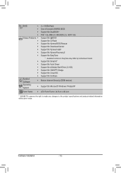
...Support for Xpress Recovery2 ŠŠ Support for EasyTune * Available functions in EasyTune may differ by motherboard model. ŠŠ Support for Smart 6™ ŠŠ Support for Auto Green Š...eXtreme Hard Drive (X.H.D) ŠŠ Support for ON/OFF Charge ŠŠ Support for Cloud OC ŠŠ Support for Q-Share Bundled Software ŠŠ Norton Internet Security (OEM version) ... ŠŠ ATX Form Factor; 30.5cm x 26.4cm * GIGABYTE reserves the right to make any changes to the product specifications and product-related information without prior notice...
...Support for Xpress Recovery2 ŠŠ Support for EasyTune * Available functions in EasyTune may differ by motherboard model. ŠŠ Support for Smart 6™ ŠŠ Support for Auto Green Š...eXtreme Hard Drive (X.H.D) ŠŠ Support for ON/OFF Charge ŠŠ Support for Cloud OC ŠŠ Support for Q-Share Bundled Software ŠŠ Norton Internet Security (OEM version) ... ŠŠ ATX Form Factor; 30.5cm x 26.4cm * GIGABYTE reserves the right to make any changes to the product specifications and product-related information without prior notice...

Manual
Page 13
... Alignment Key 1 LGA1366 CPU Triangle Pin One Marking on the CPU. It is not installed, otherwise overheating and dam- Locate the alignment keys on the motherboard CPU socket and the notches on the CPU Notch Notch - 13 - LGA1366 CPU Socket Pin One Corner of thermal grease on the computer if the...
... Alignment Key 1 LGA1366 CPU Triangle Pin One Marking on the CPU. It is not installed, otherwise overheating and dam- Locate the alignment keys on the motherboard CPU socket and the notches on the CPU Notch Notch - 13 - LGA1366 CPU Socket Pin One Corner of thermal grease on the computer if the...

Manual
Page 14
... sure to turn off the computer and unplug the power cord from the power outlet to prevent damage to correctly install the CPU into the motherboard CPU socket. B.
... sure to turn off the computer and unplug the power cord from the power outlet to prevent damage to correctly install the CPU into the motherboard CPU socket. B.
Manual
Page 15
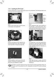
...shows, the installation is to install.) Step 3: Place the cooler atop the CPU, aligning the four push pins through the pin holes on the motherboard. Use extreme care when removing the CPU cooler because the thermal grease/tape between the CPU cooler and CPU may damage the CPU. - 15...) on the male push pin. (Turning the push pin along the direction of the installed CPU. Step 6: Finally, attach the power connector of the motherboard. Hardware Installation Step 4: You should hear a "click" when pushing down on the contrary, is complete. If the push pin is inserted as the ...
...shows, the installation is to install.) Step 3: Place the cooler atop the CPU, aligning the four push pins through the pin holes on the motherboard. Use extreme care when removing the CPU cooler because the thermal grease/tape between the CPU cooler and CPU may damage the CPU. - 15...) on the male push pin. (Turning the push pin along the direction of the installed CPU. Step 6: Finally, attach the power connector of the motherboard. Hardware Installation Step 4: You should hear a "click" when pushing down on the contrary, is complete. If the push pin is inserted as the ...

Manual
Page 16
... enabling Dual Channel mode with three memory modules, be sure to insert the memory, switch the direction. 1-4-1 Dual/3 Channel Memory Configuration This motherboard provides six DDR3 memory sockets and supports Dual/3 Channel Technology. When enabling 3 Channel mode with two memory modules, be sure to install the...install them in Dual or 3 Channel mode. When enabling Dual Channel mode with four memory modules, be used . (Go to GIGABYTE's website for the latest supported memory speeds and momery modules.) • Always turn off the computer and unplug the power cord from...
... enabling Dual Channel mode with three memory modules, be sure to insert the memory, switch the direction. 1-4-1 Dual/3 Channel Memory Configuration This motherboard provides six DDR3 memory sockets and supports Dual/3 Channel Technology. When enabling 3 Channel mode with two memory modules, be sure to install the...install them in Dual or 3 Channel mode. When enabling Dual Channel mode with four memory modules, be used . (Go to GIGABYTE's website for the latest supported memory speeds and momery modules.) • Always turn off the computer and unplug the power cord from...

Manual
Page 17
... memory socket. Hardware Installation As indica1ted in the picture on the left, place your memory modules in one direction. Place the memory module on this motherboard. Notch 1 DDR3 DIMM A DDR3 memory module has a notch, so it vertically into place when the memory module is securely inserted. - 17 - Step 1: Note the orientation...
... memory socket. Hardware Installation As indica1ted in the picture on the left, place your memory modules in one direction. Place the memory module on this motherboard. Notch 1 DDR3 DIMM A DDR3 memory module has a notch, so it vertically into place when the memory module is securely inserted. - 17 - Step 1: Note the orientation...
Manual
Page 18
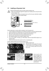
... the chassis back panel. 2. Remove the metal slot cover from the power outlet before you begin to install an expansion card: • Make sure the motherboard supports the expansion card. If necessary, go to BIOS Setup to make any required BIOS changes for your computer. Carefully read the manual that supports...
... the chassis back panel. 2. Remove the metal slot cover from the power outlet before you begin to install an expansion card: • Make sure the motherboard supports the expansion card. If necessary, go to BIOS Setup to make any required BIOS changes for your computer. Carefully read the manual that supports...
Manual
Page 19
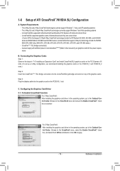
... technology include the ATI Radeon HD 3800, HD 4800, and HD 5800 series and AMD Radeon HD 6950 and HD 6970 series. A CrossFireX/SLI-supported motherboard with sufficient power is selected. CrossFireX/SLI-supported graphics cards of ATI CrossFireX™/NVIDIA SLI Configuration A. Connecting the Graphics Cards Step 1: Observe the steps...
... technology include the ATI Radeon HD 3800, HD 4800, and HD 5800 series and AMD Radeon HD 6950 and HD 6970 series. A CrossFireX/SLI-supported motherboard with sufficient power is selected. CrossFireX/SLI-supported graphics cards of ATI CrossFireX™/NVIDIA SLI Configuration A. Connecting the Graphics Cards Step 1: Observe the steps...

Manual
Page 21
... default line in jack. Microphones must be used to prevent an electrical short inside the cable connector. Do not rock it straight out from the motherboard. • When removing the cable, pull it side to side to connect front speakers in devices such as a USB keyboard/mouse, USB printer, USB flash...
... default line in jack. Microphones must be used to prevent an electrical short inside the cable connector. Do not rock it straight out from the motherboard. • When removing the cable, pull it side to side to connect front speakers in devices such as a USB keyboard/mouse, USB printer, USB flash...
Manual
Page 24
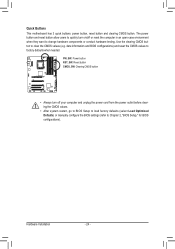
... Optimized Defaults) or manually configure the BIOS settings (refer to change hardware components or conduct hardware testing. Hardware Installation - 24 - DIP 1 23 Quick Buttons This motherboard has 3 quick buttons: power button, reset button and clearing CMOS button. The power button and reset button allow users to quickly turn off or reset...
... Optimized Defaults) or manually configure the BIOS settings (refer to change hardware components or conduct hardware testing. Hardware Installation - 24 - DIP 1 23 Quick Buttons This motherboard has 3 quick buttons: power button, reset button and clearing CMOS button. The power button and reset button allow users to quickly turn off or reset...

Manual
Page 25
..., make sure your devices are compliant with the connectors you wish to connect. • Before installing the devices, be sure to the connector on the motherboard. - 25 - Hardware Installation Unplug the power cord from the power outlet to prevent damage to the devices. • After installing the device and before connecting...
..., make sure your devices are compliant with the connectors you wish to connect. • Before installing the devices, be sure to the connector on the motherboard. - 25 - Hardware Installation Unplug the power cord from the power outlet to prevent damage to the devices. • After installing the device and before connecting...

Manual
Page 26
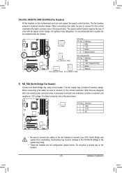
... CPU manufacturer when using an Intel Extreme Edition CPU (130W). • To meet expansion requirements, it is turned off and all the components on the motherboard. Before connecting the power connector, first make sure the power supply is recommended that a power supply that does not provide the required power, the result...
... CPU manufacturer when using an Intel Extreme Edition CPU (130W). • To meet expansion requirements, it is turned off and all the components on the motherboard. Before connecting the power connector, first make sure the power supply is recommended that a power supply that does not provide the required power, the result...
Manual
Page 27
... connecting a fan cable, be sure to connect it in the correct orientation (the black connector wire is recommended that a system fan be sure to this motherboard are 4-pin and support fan speed control function. When connecting a fan cable, be installed inside the chassis. DIP 1 23 1 Pin No. For optimum heat dissipation...
... connecting a fan cable, be sure to connect it in the correct orientation (the black connector wire is recommended that a system fan be sure to this motherboard are 4-pin and support fan speed control function. When connecting a fan cable, be installed inside the chassis. DIP 1 23 1 Pin No. For optimum heat dissipation...


