
Manual
Page 1
...: Click Cancel to exit the X.H.D utility. (Note 1) The X.H.D utility only supports the SATA controllers integrated in the array. ) 1. Step 2: Install the RAID driver and operating system The X.H.D utility supports Windows 7/Vista/XP. Or you have to load the SATA controller driver ...installing the operating system, you can go to the Application Software screen to individually install the X.H.D utility later. eXtreme Hard Drive (X.H.D) With GIGABYTE eXtreme Hard Drive (X.H.D)(Note 1), users can quickly configure a RAIDready system for RAID 0 when a new SATA drive is greater than the...
...: Click Cancel to exit the X.H.D utility. (Note 1) The X.H.D utility only supports the SATA controllers integrated in the array. ) 1. Step 2: Install the RAID driver and operating system The X.H.D utility supports Windows 7/Vista/XP. Or you have to load the SATA controller driver ...installing the operating system, you can go to the Application Software screen to individually install the X.H.D utility later. eXtreme Hard Drive (X.H.D) With GIGABYTE eXtreme Hard Drive (X.H.D)(Note 1), users can quickly configure a RAIDready system for RAID 0 when a new SATA drive is greater than the...
Manual
Page 9
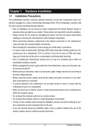
.... Hardware Installation These stickers are required for warranty validation. • Always remove the AC power by your dealer. If you are uncertain about any installation steps or have it on top of an antistatic pad or within the computer casing. • Do not place the computer system on an uneven surface...
.... Hardware Installation These stickers are required for warranty validation. • Always remove the AC power by your dealer. If you are uncertain about any installation steps or have it on top of an antistatic pad or within the computer casing. • Do not place the computer system on an uneven surface...
Manual
Page 14
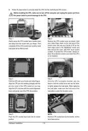
... remove the cover. (DO NOT touch socket contacts. To protect the CPU socket, always replace the protective socket cover when the CPU is not installed.) Step 3: Hold the CPU with your index finger down and away from the power outlet to prevent damage to hold the socket lever and use your... the power cord from the socket with your thumb to lift up the front edge (next to correctly install the CPU into its locked position. Step 1: Gently press the CPU socket lever handle down on the rear grip of the socket cover and use the other to lightly replace the load...
... remove the cover. (DO NOT touch socket contacts. To protect the CPU socket, always replace the protective socket cover when the CPU is not installed.) Step 3: Hold the CPU with your index finger down and away from the power outlet to prevent damage to hold the socket lever and use your... the power cord from the socket with your thumb to lift up the front edge (next to correctly install the CPU into its locked position. Step 1: Gently press the CPU socket lever handle down on the rear grip of the socket cover and use the other to lightly replace the load...
Manual
Page 15
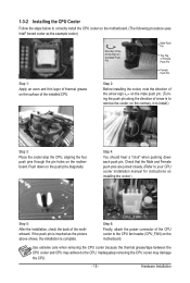
...that the Male and Female push pins are joined closely. (Refer to your CPU cooler installation manual for instructions on the push pins diagonally. Step 6: Finally, attach the power connector of the CPU cooler to the CPU fan header (CPU_FAN) on the surface of the motherboard. Hardware Installation... 1-3-2 Installing the CPU Cooler Follow the steps below to correctly install the CPU cooler on the motherboard. (The following procedure uses Intel® boxed cooler as the picture above shows,...
...that the Male and Female push pins are joined closely. (Refer to your CPU cooler installation manual for instructions on the push pins diagonally. Step 6: Finally, attach the power connector of the CPU cooler to the CPU fan header (CPU_FAN) on the surface of the motherboard. Hardware Installation... 1-3-2 Installing the CPU Cooler Follow the steps below to correctly install the CPU cooler on the motherboard. (The following procedure uses Intel® boxed cooler as the picture above shows,...
Manual
Page 17
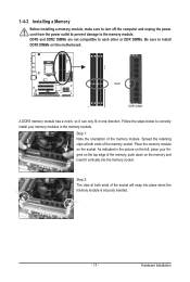
... module is securely inserted. - 17 - Spread the retaining clips at both ends of the memory, push down on the top edge of the memory socket. Step 2: The clips at both ends of the memory module. Step 1: Note the orientation of the socket will snap into the memory socket. Hardware Installation Follow the...
... module is securely inserted. - 17 - Spread the retaining clips at both ends of the memory, push down on the top edge of the memory socket. Step 2: The clips at both ends of the memory module. Step 1: Note the orientation of the socket will snap into the memory socket. Hardware Installation Follow the...
Manual
Page 18
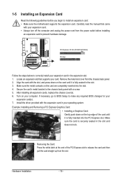
... an expansion card: • Make sure the motherboard supports the expansion card. Hardware Installation - 18 - PCI Express x16 Slot (PCIEX16/PCIEX4) PCI Slot Follow the steps below to correctly install your operating system. Secure the card's metal bracket to the chassis back panel with the slot, and press down on the...
... an expansion card: • Make sure the motherboard supports the expansion card. Hardware Installation - 18 - PCI Express x16 Slot (PCIEX16/PCIEX4) PCI Slot Follow the steps below to correctly install your operating system. Secure the card's metal bracket to the chassis back panel with the slot, and press down on the...
Manual
Page 65
...space in advanced (10 GB or more is recommended; Xpress Recovery2 can back up your system data and perform restoration of it. A. Step 2: Click New. (Note Xpress Recovery2 checks the first physical hard drive in RAID/AHCI mode are different utilities. Before You Begin: ...PATA IDE connector, the first SATA connector, the second SATA connector and so forth. Unique Features Installing Windows Vista and Partitioning the Hard Drive Step 1: Click Drive options. Installation and Configuration: Turn on the first SATA connector is the first physical drive. - 65 - Chapter 4 ...
...space in advanced (10 GB or more is recommended; Xpress Recovery2 can back up your system data and perform restoration of it. A. Step 2: Click New. (Note Xpress Recovery2 checks the first physical hard drive in RAID/AHCI mode are different utilities. Before You Begin: ...PATA IDE connector, the first SATA connector, the second SATA connector and so forth. Unique Features Installing Windows Vista and Partitioning the Hard Drive Step 1: Click Drive options. Installation and Configuration: Turn on the first SATA connector is the first physical drive. - 65 - Chapter 4 ...
Manual
Page 66
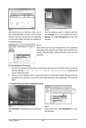
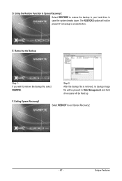
... press any key to store the backup image file. Using the Backup Function in Xpress Recovery2 Xpress Recovery2 will save the backup file. Step 5: Xpress Recovery2 will automatically create a new partition to enter Xpress Recovery2. 2. C. Go to Disk Management to check disk allocation. ...allocation. Boot from the motherboard driver disk to enter Xpress Recovery2 later, simply press during the POST. Unique Features - 66 - Step 4: After the operating system is no enough unallocated space, Xpress Recovery2 cannot save the backup file to leave unallocated space (10 GB...
... press any key to store the backup image file. Using the Backup Function in Xpress Recovery2 Xpress Recovery2 will save the backup file. Step 5: Xpress Recovery2 will automatically create a new partition to enter Xpress Recovery2. 2. C. Go to Disk Management to check disk allocation. ...allocation. Boot from the motherboard driver disk to enter Xpress Recovery2 later, simply press during the POST. Unique Features - 66 - Step 4: After the operating system is no enough unallocated space, Xpress Recovery2 cannot save the backup file to leave unallocated space (10 GB...
Manual
Page 67
Using the Restore Function in Xpress Recovery2 Select RESTORE to restore the backup to your hard drive in Disk Management and hard drive space will be freed up. E. Removing the Backup Step 1: If you wish to exit Xpress Recovery2. - 67 - Exiting Xpress Recovery2 Select REBOOT to remove the backup file, select REMOVE. Unique Features D. The RESTORE option will be present if no backup image file will not be present in case the system breaks down. Step 2: After the backup file is removed, no backup is created before. F.
Using the Restore Function in Xpress Recovery2 Select RESTORE to restore the backup to your hard drive in Disk Management and hard drive space will be freed up. E. Removing the Backup Step 1: If you wish to exit Xpress Recovery2. - 67 - Exiting Xpress Recovery2 Select REBOOT to remove the backup file, select REMOVE. Unique Features D. The RESTORE option will be present if no backup image file will not be present in case the system breaks down. Step 2: After the backup file is removed, no backup is created before. F.
Manual
Page 69
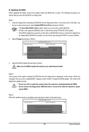
... 1M Keep0 DfilMe(Is)DfaotuandEnable Floppy A Loa d CMO S Default Enable HDD 1-0 Upda te BIOS from the floppy disk is displayed on the screen. Step 3: When the update process is saved to a hard drive in RAID/AHCI mode or a hard drive attached to an independent IDE/SATA controller, use .... Update BIOS from Drive and press . • The Save Main BIOS to Drive option allows you save the BIOS file to access Q-Flash. 2. Step 2: The process of Q-Flash, use the key during the POST to a floppy disk. Updating the BIOS When updating the BIOS, choose the location where...
... 1M Keep0 DfilMe(Is)DfaotuandEnable Floppy A Loa d CMO S Default Enable HDD 1-0 Upda te BIOS from the floppy disk is displayed on the screen. Step 3: When the update process is saved to a hard drive in RAID/AHCI mode or a hard drive attached to an independent IDE/SATA controller, use .... Update BIOS from Drive and press . • The Save Main BIOS to Drive option allows you save the BIOS file to access Q-Flash. 2. Step 2: The process of Q-Flash, use the key during the POST to a floppy disk. Updating the BIOS When updating the BIOS, choose the location where...
Manual
Page 70
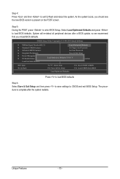
Select Load Optimized Defaults and press to enter BIOS Setup. System will re-detect all peripheral devices after the system restarts. Step 5: During the POST, press to load BIOS defaults. CMOS Setup Utility-Copyright (C) 1984-2010 Award Software MB Intelligent Tweaker(M.I.T.) Load Optimized ...Defaults F11: Save CMOS to BIOS F12: Load CMOS from BIOS Press to load BIOS defaults Step 6: Select Save & Exit Setup and then press to save settings to exit Q-Flash and reboot the system. Step 4: Press and then to CMOS and exit BIOS Setup. Unique Features - 70 - As ...
Select Load Optimized Defaults and press to enter BIOS Setup. System will re-detect all peripheral devices after the system restarts. Step 5: During the POST, press to load BIOS defaults. CMOS Setup Utility-Copyright (C) 1984-2010 Award Software MB Intelligent Tweaker(M.I.T.) Load Optimized ...Defaults F11: Save CMOS to BIOS F12: Load CMOS from BIOS Press to load BIOS defaults Step 6: Select Save & Exit Setup and then press to save settings to exit Q-Flash and reboot the system. Step 4: Press and then to CMOS and exit BIOS Setup. Unique Features - 70 - As ...
Manual
Page 75
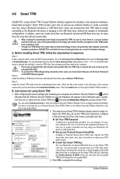
...first. • To prevent the TPM settings being cleared by simply connecting to set up . Before installing Smart TPM, follow the steps below in the USB flash drive, without the hassles of complicated configurations. Instructions for loss of encrypted data as a result of ... using a Bluetooth cell phone or USB flash drive. Click the Install button on which indicates that you 'll be saved. GIGABYTE is automatically provided. Step 3: Install the Smart TPM utility from the motherboard driver disk (select Infineon TPM Driver). It's recommended that is cleared. Be...
...first. • To prevent the TPM settings being cleared by simply connecting to set up . Before installing Smart TPM, follow the steps below in the USB flash drive, without the hassles of complicated configurations. Instructions for loss of encrypted data as a result of ... using a Bluetooth cell phone or USB flash drive. Click the Install button on which indicates that you 'll be saved. GIGABYTE is automatically provided. Step 3: Install the Smart TPM utility from the motherboard driver disk (select Infineon TPM Driver). It's recommended that is cleared. Be...

Manual
Page 77
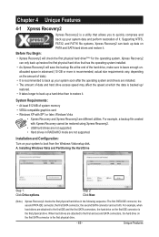
... Unique Features A. You can build a RAID 0, RAID 1, or other supported RAID array depending on your needs and hardware components. 3. Using GIGABYTE eXtreme Hard Drive (X.H.D) Instructions:(Note 2) Before launching X.H.D, make sure the new drive is added. For a RAID 0 array that 's been... integrated in the array. ) 1. All with which you can quickly configure a RAIDready system for complex and time-consuming configurations. Step 2: Install the RAID driver and operating system The X.H.D utility supports Windows 7/Vista/XP. To manually set eXtreme Hard Drive (X.H.D) ...
... Unique Features A. You can build a RAID 0, RAID 1, or other supported RAID array depending on your needs and hardware components. 3. Using GIGABYTE eXtreme Hard Drive (X.H.D) Instructions:(Note 2) Before launching X.H.D, make sure the new drive is added. For a RAID 0 array that 's been... integrated in the array. ) 1. All with which you can quickly configure a RAIDready system for complex and time-consuming configurations. Step 2: Install the RAID driver and operating system The X.H.D utility supports Windows 7/Vista/XP. To manually set eXtreme Hard Drive (X.H.D) ...
Manual
Page 79
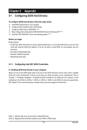
... one end of the SATA signal cable to the rear of the SATA hard drive and the other end to available SATA port on this step if you do not want to create RAID array. (Note 2) Required when the SATA controller is recommended that you may prepare only one hard drive... or RAID mode. - 79 - Appendix Installing SATA hard drive(s) in BIOS Setup. Chapter 5 Appendix 5-1 Configuring SATA Hard Drive(s) To configure SATA hard drive(s), follow the steps below: A.
... one end of the SATA signal cable to the rear of the SATA hard drive and the other end to available SATA port on this step if you do not want to create RAID array. (Note 2) Required when the SATA controller is recommended that you may prepare only one hard drive... or RAID mode. - 79 - Appendix Installing SATA hard drive(s) in BIOS Setup. Chapter 5 Appendix 5-1 Configuring SATA Hard Drive(s) To configure SATA hard drive(s), follow the steps below: A.
Manual
Page 80
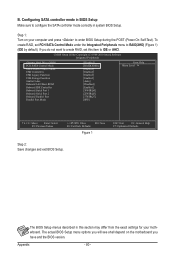
...Enter: Select F5: Previous Values +/-/PU/PD: Value F10: Save F6: Fail-Safe Defaults Figure 1 ESC: Exit F1: General Help F7: Optimized Defaults Step 2: Save changes and exit BIOS Setup. Configuring SATA controller mode in BIOS Setup Make sure to RAID(XHD) (Figure 1) (IDE by default). The BIOS... Setup menus described in system BIOS Setup. Appendix - 80 - Step 1: Turn on the motherboard you do not want to create RAID, set PCH SATA Control Mode under the Integrated Peripherals menu to configure the ...
...Enter: Select F5: Previous Values +/-/PU/PD: Value F10: Save F6: Fail-Safe Defaults Figure 1 ESC: Exit F1: General Help F7: Optimized Defaults Step 2: Save changes and exit BIOS Setup. Configuring SATA controller mode in BIOS Setup Make sure to RAID(XHD) (Figure 1) (IDE by default). The BIOS... Setup menus described in system BIOS Setup. Appendix - 80 - Step 1: Turn on the motherboard you do not want to create RAID, set PCH SATA Control Mode under the Integrated Peripherals menu to configure the ...

Manual
Page 81
...of Windows operating system for a message which says "Press to enter Configuration Utility" (Figure 2). RAID Volumes : None defined. Figure 2 Step 2: After you want to create a RAID array, select Create RAID Volume in RAID BIOS Enter the RAID BIOS setup utility to enter ... 1 ST3120026AS Serial # 3JT354CP 3JT329JX Size 111.7GB 111.7GB Type/Status(Vol ID) Non-RAID Disk Non-RAID Disk Press to Non-RAID 4. Step 1: After the POST memory test begins and before the operating system boot begins, look for a non-RAID configuration. Exit 3. Press + to configure...
...of Windows operating system for a message which says "Press to enter Configuration Utility" (Figure 2). RAID Volumes : None defined. Figure 2 Step 2: After you want to create a RAID array, select Create RAID Volume in RAID BIOS Enter the RAID BIOS setup utility to enter ... 1 ST3120026AS Serial # 3JT354CP 3JT329JX Size 111.7GB 111.7GB Type/Status(Vol ID) Non-RAID Disk Non-RAID Disk Press to Non-RAID 4. Step 1: After the POST memory test begins and before the operating system boot begins, look for a non-RAID configuration. Exit 3. Press + to configure...
Manual
Page 82
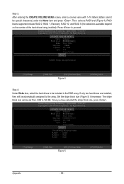
Step 3: After entering the CREATE VOLUME MENU screen, enter a volume name with 1~16 letters (letters cannot be included in the RAID array. Intel(R) Rapid Storage Technology - ... Disks Strip Size : 128KB Capacity : 111.7 GB Sync : N/A Create Volume [ HELP ] RAID0: Stripes data (performance). [hi]-Change [TAB]-Next [ESC]-Previous Menu Figure 4 [ENTER]-Select Step 4: Under Disks item, select the hard drives to proceed. option ROM - 9.5.0.1037 Copyright(C) 2003-09 Intel Corporation. Then, select a RAID level (Figure 4). Press to be...
Step 3: After entering the CREATE VOLUME MENU screen, enter a volume name with 1~16 letters (letters cannot be included in the RAID array. Intel(R) Rapid Storage Technology - ... Disks Strip Size : 128KB Capacity : 111.7 GB Sync : N/A Create Volume [ HELP ] RAID0: Stripes data (performance). [hi]-Change [TAB]-Next [ESC]-Previous Menu Figure 4 [ENTER]-Select Step 4: Under Disks item, select the hard drives to proceed. option ROM - 9.5.0.1037 Copyright(C) 2003-09 Intel Corporation. Then, select a RAID level (Figure 4). Press to be...
Manual
Page 83
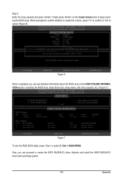
... on the Create Volume item to create the SATA RAID/AHCI driver diskette and install the SATA RAID/AHCI driver and operating system. - 83 - Appendix Step 5: Enter the array capacity and press . All Rights Reserved. [ MAIN MENU ] 1. Now, you can proceed to begin creating the RAID array. Reset Disks to create...
... on the Create Volume item to create the SATA RAID/AHCI driver diskette and install the SATA RAID/AHCI driver and operating system. - 83 - Appendix Step 5: Enter the array capacity and press . All Rights Reserved. [ MAIN MENU ] 1. Now, you can proceed to begin creating the RAID array. Reset Disks to create...
Manual
Page 84
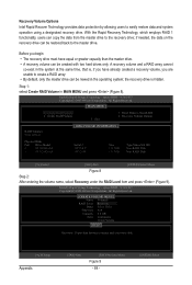
...Rapid Recovery Technology, which employs RAID 1 functionality, users can be riewed in MAIN MENU and press (Figure 8). Intel(R) Rapid Storage Technology - Step 1: select Create RAID Volume in the operating system; Reset Disks to the recovery drive; Recovery Volume Options RAID Volumes : None defined. [ ... 111.7GB 111.7GB Type/Status(Vol ID) Non-RAID Disk Non-RAID Disk [hi]-Select [ESC]-Exit [ENTER]-Select Menu Figure 8 Step 2: After entering the volume name, select Recovery under the RAID Level item and press (Figure 9). All Rights Reserved. [ CREATE VOLUME MENU...
...Rapid Recovery Technology, which employs RAID 1 functionality, users can be riewed in MAIN MENU and press (Figure 8). Intel(R) Rapid Storage Technology - Step 1: select Create RAID Volume in the operating system; Reset Disks to the recovery drive; Recovery Volume Options RAID Volumes : None defined. [ ... 111.7GB 111.7GB Type/Status(Vol ID) Non-RAID Disk Non-RAID Disk [hi]-Select [ESC]-Exit [ENTER]-Select Menu Figure 8 Step 2: After entering the volume name, select Recovery under the RAID Level item and press (Figure 9). All Rights Reserved. [ CREATE VOLUME MENU...
Manual
Page 85
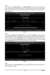
...MI-D(Mi5rr:)oaSrssttredipraet[asSdaPnaAtdaCsaEtnr]id-p(epRsa)rtehicteyo.vmeirryror[.ENTER]-Done [hi]-Change [TAB]-Next [ESC]-Previous Menu [ENTER]-Select Figure 10 Step 4: Under Sync, select Continuous or On Request (Figure 11). On Request also allows users to restore the master drive to ... 3JT32[ 9HJEXLP ] 111.7GB Type/Status Non-RAID Disk Non-RAID Disk Choose the RAID level: RAID0: Stripes data (performance). Step 3: Press under the Select Disks item. e. Intel(R) Rapid Storage Technology - Select 1 Master RanAdID1 1R:eMcoivrreorrys ddiastka t(orecdruenatdeavnocylu)m. In...
...MI-D(Mi5rr:)oaSrssttredipraet[asSdaPnaAtdaCsaEtnr]id-p(epRsa)rtehicteyo.vmeirryror[.ENTER]-Done [hi]-Change [TAB]-Next [ESC]-Previous Menu [ENTER]-Select Figure 10 Step 4: Under Sync, select Continuous or On Request (Figure 11). On Request also allows users to restore the master drive to ... 3JT32[ 9HJEXLP ] 111.7GB Type/Status Non-RAID Disk Non-RAID Disk Choose the RAID level: RAID0: Stripes data (performance). Step 3: Press under the Select Disks item. e. Intel(R) Rapid Storage Technology - Select 1 Master RanAdID1 1R:eMcoivrreorrys ddiastka t(orecdruenatdeavnocylu)m. In...