
Manual
Page 1
... the biggest drive in the Intel Chipset. (Note 2) It is added. Before installing the operating system, you can quickly configure a RAIDready system for RAID 0. Or you have to load the SATA controller driver first. eXtreme Hard Drive (X.H.D) With GIGABYTE eXtreme Hard Drive (X.H.D)(Note 1), users can go to the Application Software screen to...
... the biggest drive in the Intel Chipset. (Note 2) It is added. Before installing the operating system, you can quickly configure a RAIDready system for RAID 0. Or you have to load the SATA controller driver first. eXtreme Hard Drive (X.H.D) With GIGABYTE eXtreme Hard Drive (X.H.D)(Note 1), users can go to the Application Software screen to...

Manual
Page 3
... example, "REV: 1.0" means the revision of the motherboard is the property of the product, read the Quick Installation Guide included with the product. For product-related information, check on our website at: http://www.gigabyte.com.tw Identifying Your Motherboard Revision The revision number on our website. Copyright © 2009 GIGA-BYTE...
... example, "REV: 1.0" means the revision of the motherboard is the property of the product, read the Quick Installation Guide included with the product. For product-related information, check on our website at: http://www.gigabyte.com.tw Identifying Your Motherboard Revision The revision number on our website. Copyright © 2009 GIGA-BYTE...

Manual
Page 4
Table of Contents Box Contents...6 Optional Items...6 GA-P55M-UD2 Motherboard Layout 7 Block Diagram...8 Chapter 1 Hardware Installation 9 1-1 Installation Precautions 9 1-2 Product Specifications 10 1-3 Installing the CPU and CPU Cooler 13 1-3-1 Installing the CPU 13 1-3-2 Installing the CPU Cooler 15 1-4 Installing the Memory 16 1-4-1 Dual Channel Memory Configuration 16 1-4-2 Installing a Memory 17 1-5 Installing an Expansion Card 18 1-6 Back Panel Connectors 19 1-7 Internal Connectors 21...
Table of Contents Box Contents...6 Optional Items...6 GA-P55M-UD2 Motherboard Layout 7 Block Diagram...8 Chapter 1 Hardware Installation 9 1-1 Installation Precautions 9 1-2 Product Specifications 10 1-3 Installing the CPU and CPU Cooler 13 1-3-1 Installing the CPU 13 1-3-2 Installing the CPU Cooler 15 1-4 Installing the Memory 16 1-4-1 Dual Channel Memory Configuration 16 1-4-2 Installing a Memory 17 1-5 Installing an Expansion Card 18 1-6 Back Panel Connectors 19 1-7 Internal Connectors 21...

Manual
Page 5
Chapter 3 Drivers Installation 61 3-1 Installing Chipset Drivers 61 3-2 Application Software 62 3-3 Technical Manuals 62 3-4 Contact...63 3-5 System...63 3-6 Download Center 64 3-7 New Utilities...64 Chapter 4 ...; ...76 Chapter 5 Appendix...79 5-1 Configuring SATA Hard Drive(s 79 5-1-1 Configuring Intel P55 SATA Controllers 79 5-1-2 Configuring GIGABYTE SATA2 SATA Controller 87 5-1-3 Making a SATA RAID/AHCI Driver Diskette 93 5-1-4 Installing the SATA RAID/AHCI Driver and Operating System 94 5-2 Configuring Audio Input and Output 105 5-2-1 Configuring 2/4/5.1/7.1-Channel Audio 105 ...
Chapter 3 Drivers Installation 61 3-1 Installing Chipset Drivers 61 3-2 Application Software 62 3-3 Technical Manuals 62 3-4 Contact...63 3-5 System...63 3-6 Download Center 64 3-7 New Utilities...64 Chapter 4 ...; ...76 Chapter 5 Appendix...79 5-1 Configuring SATA Hard Drive(s 79 5-1-1 Configuring Intel P55 SATA Controllers 79 5-1-2 Configuring GIGABYTE SATA2 SATA Controller 87 5-1-3 Making a SATA RAID/AHCI Driver Diskette 93 5-1-4 Installing the SATA RAID/AHCI Driver and Operating System 94 5-2 Configuring Audio Input and Output 105 5-2-1 Configuring 2/4/5.1/7.1-Channel Audio 105 ...
Manual
Page 6
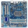
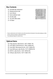
Box Contents GA-P55M-UD2 motherboard Motherboard driver disk User's Manual Quick Installation Guide One IDE cable Two SATA 3Gb/s cables I/O Shield • The box contents above are subject to change without notice. • The motherboard image is ...
Box Contents GA-P55M-UD2 motherboard Motherboard driver disk User's Manual Quick Installation Guide One IDE cable Two SATA 3Gb/s cables I/O Shield • The box contents above are subject to change without notice. • The motherboard image is ...
Manual
Page 9
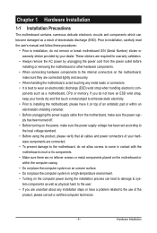
...not place the computer system in a high-temperature environment. • Turning on the power, make sure they are uncertain about any installation steps or have it on top of an antistatic pad or within an electrostatic shielding container. • Before unplugging the power supply ...cable from the power outlet before installing or removing the motherboard or other hardware components. • When connecting hardware components to the internal connectors on the motherboard, make...
...not place the computer system in a high-temperature environment. • Turning on the power, make sure they are uncertain about any installation steps or have it on top of an antistatic pad or within an electrostatic shielding container. • Before unplugging the power supply ...cable from the power outlet before installing or removing the motherboard or other hardware components. • When connecting hardware components to the internal connectors on the motherboard, make...

Manual
Page 10
...1, and JBOD w iTE IT8720 chip: - 1 x floppy disk drive connector supporting up to 2 SATA 3Gb/s devices - Support for SATA RAID 0, RAID 1, RAID 5, and RAID 10 w GIGABYTE SATA2 chip: - 1 x IDE connector supporting ATA-133/100/66/33 and up to 2 IDE devices - 2 x SATA 3Gb/s connectors (GSATA2_0, GSATA2_1) supporting up to 1 SATA 3Gb..., SATA2_2, SATA2_3, SATA2_4) supporting up to 5 SATA 3Gb/s devices - 1 x eSATA 3Gb/s connector on the back panel supporting up to 1 floppy disk drive Hardware Installation - 10 -
...1, and JBOD w iTE IT8720 chip: - 1 x floppy disk drive connector supporting up to 2 SATA 3Gb/s devices - Support for SATA RAID 0, RAID 1, RAID 5, and RAID 10 w GIGABYTE SATA2 chip: - 1 x IDE connector supporting ATA-133/100/66/33 and up to 2 IDE devices - 2 x SATA 3Gb/s connectors (GSATA2_0, GSATA2_1) supporting up to 1 SATA 3Gb..., SATA2_2, SATA2_3, SATA2_4) supporting up to 5 SATA 3Gb/s devices - 1 x eSATA 3Gb/s connector on the back panel supporting up to 1 floppy disk drive Hardware Installation - 10 -

Manual
Page 11
Hardware Installation USB w IEEE 1394 w Internal w Connectors w w w w w w w w w w w w w w w Back Panel w Connectors w w w w w w w I . TSB43AB23 chip Up to 2 IEEE 1394a ports (1 on the back panel, 4 via the USB brackets connected to ...
Hardware Installation USB w IEEE 1394 w Internal w Connectors w w w w w w w w w w w w w w w Back Panel w Connectors w w w w w w w I . TSB43AB23 chip Up to 2 IEEE 1394a ports (1 on the back panel, 4 via the USB brackets connected to ...
Manual
Page 12
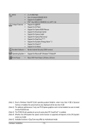
...0a, DMI 2.0, SM BIOS 2.4, ACPI 1.0b Support for @BIOS Support for Q-Flash Support for Xpress BIOS Rescue Support for Download Center Support for Xpress Install Support for Xpress Recovery2 Support for EasyTune (Note 5) Support for Dynamic Energy Saver™ 2 Support for Smart 6™ Support for Q-Share Norton Internet ...memory size displayed will be less than 4 GB. (Note 2) For optimum performance, if only one PCI Express graphics card is to be installed, be sure to install it in the PCIEX16 slot. (Note 3) The PCIEX16 slot operates at up to x4 mode when ATI CrossFireX™ is enabled. (...
...0a, DMI 2.0, SM BIOS 2.4, ACPI 1.0b Support for @BIOS Support for Q-Flash Support for Xpress BIOS Rescue Support for Download Center Support for Xpress Install Support for Xpress Recovery2 Support for EasyTune (Note 5) Support for Dynamic Energy Saver™ 2 Support for Smart 6™ Support for Q-Share Norton Internet ...memory size displayed will be less than 4 GB. (Note 2) For optimum performance, if only one PCI Express graphics card is to be installed, be sure to install it in the PCIEX16 slot. (Note 3) The PCIEX16 slot operates at up to x4 mode when ATI CrossFireX™ is enabled. (...
Manual
Page 13
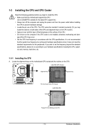
...CPU support list.) • Always turn on the computer if the CPU cooler is not recommended that the motherboard supports the CPU. (Go to GIGABYTE's website for the peripherals. age of the CPU. LGA1156 CPU Socket Alignment Key Alignment Key Pin One Corner of the CPU Socket LGA1156 CPU ...Notch Notch Triangle Pin One Marking on the CPU. It is not installed, otherwise overheating and dam- If you wish to set beyond the standard specifications, please do so according to your hardware specifications including the CPU...
...CPU support list.) • Always turn on the computer if the CPU cooler is not recommended that the motherboard supports the CPU. (Go to GIGABYTE's website for the peripherals. age of the CPU. LGA1156 CPU Socket Alignment Key Alignment Key Pin One Corner of the CPU Socket LGA1156 CPU ...Notch Notch Triangle Pin One Marking on the CPU. It is not installed, otherwise overheating and dam- If you wish to set beyond the standard specifications, please do so according to your hardware specifications including the CPU...

Manual
Page 14
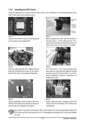
... the lever base portion. Follow the steps below to grasp the protective socket cover as well. Step 2: Use your thumb and index finger to correctly install the CPU into its locked position. Align the CPU pin one marking (triangle) with the pin one hand to lightly replace the load plate. Step... end of the CPU socket (or you may align the CPU notches with the socket alignment keys) and gently insert the CPU into position. Hardware Installation - 14 - Step 1: Gently press the CPU socket lever handle down and away from the power outlet to prevent damage to turn off the computer and...
... the lever base portion. Follow the steps below to grasp the protective socket cover as well. Step 2: Use your thumb and index finger to correctly install the CPU into its locked position. Align the CPU pin one marking (triangle) with the pin one hand to lightly replace the load plate. Step... end of the CPU socket (or you may align the CPU notches with the socket alignment keys) and gently insert the CPU into position. Hardware Installation - 14 - Step 1: Gently press the CPU socket lever handle down and away from the power outlet to prevent damage to turn off the computer and...
Manual
Page 15
...motherboard. Direction of the Arrow Sign on the Male Push Pin Male Push Pin The Top of Female Push Pin Female Push Pin Step 2: Before installing the cooler, note the direction of the arrow sign on the push pins diagonally. If the push pin is inserted as the example cooler.) ...Step 1: Apply an even and thin layer of thermal grease on the motherboard. Hardware Installation Use extreme care when removing the CPU cooler because the thermal grease/tape between the CPU cooler and CPU may damage the CPU. - 15 - ...
...motherboard. Direction of the Arrow Sign on the Male Push Pin Male Push Pin The Top of Female Push Pin Female Push Pin Step 2: Before installing the cooler, note the direction of the arrow sign on the push pins diagonally. If the push pin is inserted as the example cooler.) ...Step 1: Apply an even and thin layer of thermal grease on the motherboard. Hardware Installation Use extreme care when removing the CPU cooler because the thermal grease/tape between the CPU cooler and CPU may damage the CPU. - 15 - ...

Manual
Page 16
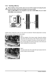
... installed in only one DDR3 memory module is installed, it is recommended to install...-"=No Memory) DDR3_2 DDR3_1 DDR3_4 DDR3_3 Due to install them in the DDR3_1 and DDR3_3 sockets. Dual ... sockets. After the memory is installed. 2. If only one direction. Hardware Installation - 16 - A memory module...power cord from the power outlet before installing the memory to insert the memory,..., speed, and chips be used . (Go to install the memory: • Make sure that memory of the... module is installed, the BIOS will double the original memory bandwidth. 1-4 Installing the Memory...
... installed in only one DDR3 memory module is installed, it is recommended to install...-"=No Memory) DDR3_2 DDR3_1 DDR3_4 DDR3_3 Due to install them in the DDR3_1 and DDR3_3 sockets. Dual ... sockets. After the memory is installed. 2. If only one direction. Hardware Installation - 16 - A memory module...power cord from the power outlet before installing the memory to insert the memory,..., speed, and chips be used . (Go to install the memory: • Make sure that memory of the... module is installed, the BIOS will double the original memory bandwidth. 1-4 Installing the Memory...
Manual
Page 17
.... Step 1: Note the orientation of the memory socket. As indicated in the picture on the left, place your memory modules in one direction. Hardware Installation Place the memory module on the memory and insert it can only fit in the memory sockets. Follow the steps below to...DDR3 and DDR2 DIMMs are not compatible to each other or DDR DIMMs. Be sure to correctly install your fingers on the top edge of the socket will snap into the memory socket. 1-4-2 Installing a Memory Before installing a memory module, make sure to turn off the computer and unplug the power cord from the...
.... Step 1: Note the orientation of the memory socket. As indicated in the picture on the left, place your memory modules in one direction. Hardware Installation Place the memory module on the memory and insert it can only fit in the memory sockets. Follow the steps below to...DDR3 and DDR2 DIMMs are not compatible to each other or DDR DIMMs. Be sure to correctly install your fingers on the top edge of the socket will snap into the memory socket. 1-4-2 Installing a Memory Before installing a memory module, make sure to turn off the computer and unplug the power cord from the...

Manual
Page 18
... expansion slot. 1. Make sure the metal contacts on the top edge of the PCI Express slot to correctly install your operating system. Secure the card's metal bracket to install an expansion card: • Make sure the motherboard supports the expansion card. If necessary, go to BIOS...unplug the power cord from the power outlet before you begin to the chassis back panel with a screw. 5. Example: Installing and Removing a PCI Express Graphics Card: • Installing a Graphics Card: Gently push down on your expansion card(s). 7. PCI Express x16 Slot PCI Slot Follow the steps ...
... expansion slot. 1. Make sure the metal contacts on the top edge of the PCI Express slot to correctly install your operating system. Secure the card's metal bracket to install an expansion card: • Make sure the motherboard supports the expansion card. If necessary, go to BIOS...unplug the power cord from the power outlet before you begin to the chassis back panel with a screw. 5. Example: Installing and Removing a PCI Express Graphics Card: • Installing a Graphics Card: Gently push down on your expansion card(s). 7. PCI Express x16 Slot PCI Slot Follow the steps ...

Manual
Page 19
... flash drive and etc. RJ-45 LAN Port The Gigabit Ethernet LAN port provides Internet connection at up to connect a PS/2 keyboard or mouse. Hardware Installation 1-6 Back Panel Connectors USB Port The USB port supports the USB 2.0/1.1 specification. PS/2 Keyboard and PS/2 Mouse Port Use this port for an IEEE 1394a...
... flash drive and etc. RJ-45 LAN Port The Gigabit Ethernet LAN port provides Internet connection at up to connect a PS/2 keyboard or mouse. Hardware Installation 1-6 Back Panel Connectors USB Port The USB port supports the USB 2.0/1.1 specification. PS/2 Keyboard and PS/2 Mouse Port Use this port for an IEEE 1394a...

Manual
Page 20
... connect side speakers in a 4/5.1/7.1-channel audio configuration. This jack can be connected to this audio jack to perform different functions via the audio software. Hardware Installation - 20 - Line Out Jack (Green) The default line out jack. Rear Speaker Out Jack (Black) Use this jack. Line In Jack (Blue) The default line...
... connect side speakers in a 4/5.1/7.1-channel audio configuration. This jack can be connected to this audio jack to perform different functions via the audio software. Hardware Installation - 20 - Line Out Jack (Green) The default line out jack. Rear Speaker Out Jack (Black) Use this jack. Line In Jack (Blue) The default line...

Manual
Page 21
... before turning on the computer, make sure your computer. Unplug the power cord from the power outlet to prevent damage to the devices. • After installing the device and before connecting external devices: • First make sure the device cable has been securely attached to turn off the devices and your...
... before turning on the computer, make sure your computer. Unplug the power cord from the power outlet to prevent damage to the devices. • After installing the device and before connecting external devices: • First make sure the device cable has been securely attached to turn off the devices and your...
Manual
Page 22
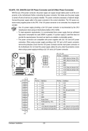
... can withstand high power consumption be used that can supply enough stable power to an unstable or unbootable system. • The power connectors are properly installed. Do not insert the power supply cables into pins under the protective covers when using a power supply providing a 2x4 12V and a 2x12 power ... 2x4-pin 12V) 2 GND (Only for 2x4-pin 12V) 3 GND 4 GND 5 +12V (Only for 2x4-pin 12V) 6 +12V (Only for 2x12-pin ATX) ATX Hardware Installation - 22 - Definition 13 3.3V 2 3.3V 14 -12V 3 GND 15 GND 4 +5V 16 PS_ON (soft On/Off) 5 GND 17 GND 6 +5V 18 GND 7 GND...
... can withstand high power consumption be used that can supply enough stable power to an unstable or unbootable system. • The power connectors are properly installed. Do not insert the power supply cables into pins under the protective covers when using a power supply providing a 2x4 12V and a 2x12 power ... 2x4-pin 12V) 2 GND (Only for 2x4-pin 12V) 3 GND 4 GND 5 +12V (Only for 2x4-pin 12V) 6 +12V (Only for 2x12-pin ATX) ATX Hardware Installation - 22 - Definition 13 3.3V 2 3.3V 14 -12V 3 GND 15 GND 4 +5V 16 PS_ON (soft On/Off) 5 GND 17 GND 6 +5V 18 GND 7 GND...
Manual
Page 23
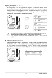
... disk drive. The pin 1 of different color. 3/4) CPU_FAN/SYS_FAN (Fan Headers) The motherboard has a 4-pin CPU fan header (CPU_FAN) and a 4-pin (SYS_FAN). Hardware Installation When connecting a fan cable, be installed inside the chassis. 1 CPU_FAN CPU_FAN: Pin No. Definition 1 GND 2 +12V / Speed Control 3 Sense 4 Speed Control 1 SYS_FAN SYS_FAN: Pin No. 1 2 3 4 Definition GND +12V...
... disk drive. The pin 1 of different color. 3/4) CPU_FAN/SYS_FAN (Fan Headers) The motherboard has a 4-pin CPU fan header (CPU_FAN) and a 4-pin (SYS_FAN). Hardware Installation When connecting a fan cable, be installed inside the chassis. 1 CPU_FAN CPU_FAN: Pin No. Definition 1 GND 2 +12V / Speed Control 3 Sense 4 Speed Control 1 SYS_FAN SYS_FAN: Pin No. 1 2 3 4 Definition GND +12V...


