
Manual
Page 1
... details the steps to automatically and quickly set up a RAID 0 array later using the Auto function. B. eXtreme Hard Drive (X.H.D) With GIGABYTE eXtreme Hard Drive (X.H.D)(Note 1), users can quickly configure a RAIDready system for RAID 0 when a new SATA drive is recommended that before ...to automatically install all of your hard drive read/write performance without the need for complex and time-consuming configurations. Using GIGABYTE eXtreme Hard Drive (X.H.D) Instructions:(Note 2) Before launching X.H.D, make sure the new drive is greater than the RAID-ready system...
... details the steps to automatically and quickly set up a RAID 0 array later using the Auto function. B. eXtreme Hard Drive (X.H.D) With GIGABYTE eXtreme Hard Drive (X.H.D)(Note 1), users can quickly configure a RAIDready system for RAID 0 when a new SATA drive is recommended that before ...to automatically install all of your hard drive read/write performance without the need for complex and time-consuming configurations. Using GIGABYTE eXtreme Hard Drive (X.H.D) Instructions:(Note 2) Before launching X.H.D, make sure the new drive is greater than the RAID-ready system...
Manual
Page 1
GA-P55M-UD2 LGA1156 socket motherboard for Intel® Core™ i7 processor family/ Intel® Core™ i5 processor family User's Manual Rev. 1001 12ME-P55MUD2-1001R
GA-P55M-UD2 LGA1156 socket motherboard for Intel® Core™ i7 processor family/ Intel® Core™ i5 processor family User's Manual Rev. 1001 12ME-P55MUD2-1001R

Manual
Page 3
... on how to assist in this manual may be reproduced, copied, translated, transmitted, or published in this manual is protected by GIGABYTE without GIGABYTE's prior written permission. Copyright © 2009 GIGA-BYTE TECHNOLOGY CO., LTD. No part of the product, read the Quick Installation... Guide included with the product. Documentation Classifications In order to use of this product, GIGABYTE provides the following types of documentations: For quick set-up of this manual may be made by copyright laws and is 1.0. ...
... on how to assist in this manual may be reproduced, copied, translated, transmitted, or published in this manual is protected by GIGABYTE without GIGABYTE's prior written permission. Copyright © 2009 GIGA-BYTE TECHNOLOGY CO., LTD. No part of the product, read the Quick Installation... Guide included with the product. Documentation Classifications In order to use of this product, GIGABYTE provides the following types of documentations: For quick set-up of this manual may be made by copyright laws and is 1.0. ...

Manual
Page 4
Table of Contents Box Contents...6 Optional Items...6 GA-P55M-UD2 Motherboard Layout 7 Block Diagram...8 Chapter 1 Hardware Installation 9 1-1 Installation Precautions 9 1-2 Product Specifications 10 1-3 Installing the CPU and CPU Cooler 13 1-3-1 Installing the CPU 13 1-3-2 Installing the ...
Table of Contents Box Contents...6 Optional Items...6 GA-P55M-UD2 Motherboard Layout 7 Block Diagram...8 Chapter 1 Hardware Installation 9 1-1 Installation Precautions 9 1-2 Product Specifications 10 1-3 Installing the CPU and CPU Cooler 13 1-3-1 Installing the CPU 13 1-3-2 Installing the ...

Manual
Page 5
... 4-4 Dynamic Energy Saver™ 2 73 4-5 Q-Share...75 4-6 Smart 6™ ...76 Chapter 5 Appendix...79 5-1 Configuring SATA Hard Drive(s 79 5-1-1 Configuring Intel P55 SATA Controllers 79 5-1-2 Configuring GIGABYTE SATA2 SATA Controller 87 5-1-3 Making a SATA RAID/AHCI Driver Diskette 93 5-1-4 Installing the SATA RAID/AHCI Driver and Operating System 94 5-2 Configuring Audio Input and...
... 4-4 Dynamic Energy Saver™ 2 73 4-5 Q-Share...75 4-6 Smart 6™ ...76 Chapter 5 Appendix...79 5-1 Configuring SATA Hard Drive(s 79 5-1-1 Configuring Intel P55 SATA Controllers 79 5-1-2 Configuring GIGABYTE SATA2 SATA Controller 87 5-1-3 Making a SATA RAID/AHCI Driver Diskette 93 5-1-4 Installing the SATA RAID/AHCI Driver and Operating System 94 5-2 Configuring Audio Input and...
Manual
Page 6
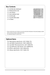
Box Contents GA-P55M-UD2 motherboard Motherboard driver disk User's Manual Quick Installation Guide One IDE cable Two SATA 3Gb/s cables I/O Shield • The box contents above are subject to ...
Box Contents GA-P55M-UD2 motherboard Motherboard driver disk User's Manual Quick Installation Guide One IDE cable Two SATA 3Gb/s cables I/O Shield • The box contents above are subject to ...

Manual
Page 7
GA-P55M-UD2 Motherboard Layout KB_USB R_SPDIF R_USB_2 CPU_FAN ATX_12V_2X4 LGA1156 PHASE LED ATX IT8720 GA-P55M-UD2 DDR3_2 DDR3_1 DDR3_4 DDR3_3 R_USB_1 USB_1394_ESATA USB_LAN RTL8111D AUDIO BAT F_AUDIO PCIEX16 PCI1 CODEC PCI2 CD_IN PCIEX4 SPDIF_O SPDIF_I FDD B_BIOS M_BIOS IDE GIGABYTE SATA2 TSB43AB23 Intel® P55 SATA2_4 CLR_CMOS SYS_FAN GSATA2_1 GSATA2_0 SATA2_1 SATA2_0 SATA2_3 SATA2_2 COMA F1_1394 F_USB2 F_USB1 F_PANEL - 7 -
GA-P55M-UD2 Motherboard Layout KB_USB R_SPDIF R_USB_2 CPU_FAN ATX_12V_2X4 LGA1156 PHASE LED ATX IT8720 GA-P55M-UD2 DDR3_2 DDR3_1 DDR3_4 DDR3_3 R_USB_1 USB_1394_ESATA USB_LAN RTL8111D AUDIO BAT F_AUDIO PCIEX16 PCI1 CODEC PCI2 CD_IN PCIEX4 SPDIF_O SPDIF_I FDD B_BIOS M_BIOS IDE GIGABYTE SATA2 TSB43AB23 Intel® P55 SATA2_4 CLR_CMOS SYS_FAN GSATA2_1 GSATA2_0 SATA2_1 SATA2_0 SATA2_3 SATA2_2 COMA F1_1394 F_USB2 F_USB1 F_PANEL - 7 -
Manual
Page 8
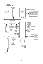
Block Diagram 1 PCI Express x16 PCIe CLK (100 MHz) LGA1156 CPU CPU CLK+/- (133 MHz) DDR3 2200/1333/1066/800 MHz Dual Channel Memory x16 PCI Express Bus DMI Interface PCI Express Bus x4 x1 x1 RTL8111D RJ45 GIGABYTE SATA2 1 PCI Express x4 LAN 2 SATA 3Gb/s ATA-133/100/66/33 IDE Channel PCI Bus TSB43AB23 Intel® P55 CODEC Dual BIOS 6 SATA 3Gb/s 14 USB Ports LPC IT8720 Bus Floppy COM PS/2 KB/Mouse 2 IEEE 1394a Surround Speaker Out Center/Subwoofer Speaker Out Side Speaker Out MIC Line Out Line In S/PDIF In S/PDIF Out 2 PCI PCI CLK (33 MHz) - 8 -
Block Diagram 1 PCI Express x16 PCIe CLK (100 MHz) LGA1156 CPU CPU CLK+/- (133 MHz) DDR3 2200/1333/1066/800 MHz Dual Channel Memory x16 PCI Express Bus DMI Interface PCI Express Bus x4 x1 x1 RTL8111D RJ45 GIGABYTE SATA2 1 PCI Express x4 LAN 2 SATA 3Gb/s ATA-133/100/66/33 IDE Channel PCI Bus TSB43AB23 Intel® P55 CODEC Dual BIOS 6 SATA 3Gb/s 14 USB Ports LPC IT8720 Bus Floppy COM PS/2 KB/Mouse 2 IEEE 1394a Surround Speaker Out Center/Subwoofer Speaker Out Side Speaker Out MIC Line Out Line In S/PDIF In S/PDIF Out 2 PCI PCI CLK (33 MHz) - 8 -
Manual
Page 9
If you are connected tightly and securely. • When handling the motherboard, avoid touching any installation steps or have it on top of an antistatic pad or within the computer casing. • Do not place the computer system on an uneven surface. • Do not place the computer system in a high-temperature environment. • Turning on the power, make sure the power supply voltage has been set according to the local voltage standard. • Before using the product, please verify that all cables and power connectors of your dealer. Prior to installation, carefully read the ...
If you are connected tightly and securely. • When handling the motherboard, avoid touching any installation steps or have it on top of an antistatic pad or within the computer casing. • Do not place the computer system on an uneven surface. • Do not place the computer system in a high-temperature environment. • Turning on the power, make sure the power supply voltage has been set according to the local voltage standard. • Before using the product, please verify that all cables and power connectors of your dealer. Prior to installation, carefully read the ...

Manual
Page 10
... floppy disk drive connector supporting up to 1 floppy disk drive Hardware Installation - 10 - Support for SATA RAID 0, RAID 1, RAID 5, and RAID 10 w GIGABYTE SATA2 chip: - 1 x IDE connector supporting ATA-133/100/66/33 and up to 2 IDE devices - 2 x SATA 3Gb/s connectors (GSATA2_0, GSATA2_1)...an Intel® Core™ i7 series processor/Intel® Core™ i5 series processor in the LGA1156 package (Go to GIGABYTE's website for the latest CPU support list.) L3 cache varies with CPU Chipset w Intel® P55 Express Chipset Memory Audio &#...
... floppy disk drive connector supporting up to 1 floppy disk drive Hardware Installation - 10 - Support for SATA RAID 0, RAID 1, RAID 5, and RAID 10 w GIGABYTE SATA2 chip: - 1 x IDE connector supporting ATA-133/100/66/33 and up to 2 IDE devices - 2 x SATA 3Gb/s connectors (GSATA2_0, GSATA2_1)...an Intel® Core™ i7 series processor/Intel® Core™ i5 series processor in the LGA1156 package (Go to GIGABYTE's website for the latest CPU support list.) L3 cache varies with CPU Chipset w Intel® P55 Express Chipset Memory Audio &#...

Manual
Page 11
Hardware Installation USB w IEEE 1394 w Internal w Connectors w w w w w w w w w w w w w w w Back Panel w Connectors w w w w w w w I/O Controller w Integrated in the Chipset Up to 14 USB 2.0/1.1 ports (10 on the back panel, 1 via the USB brackets connected to the internal IEEE 1394a header) 1 x 24-pin ATX main power connector 1 x 8-pin ATX 12V power connector 1 x floppy disk drive connector 1 x IDE connector 7 x SATA 3Gb/s connectors 1 x CPU...
Hardware Installation USB w IEEE 1394 w Internal w Connectors w w w w w w w w w w w w w w w Back Panel w Connectors w w w w w w w I/O Controller w Integrated in the Chipset Up to 14 USB 2.0/1.1 ports (10 on the back panel, 1 via the USB brackets connected to the internal IEEE 1394a header) 1 x 24-pin ATX main power connector 1 x 8-pin ATX 12V power connector 1 x floppy disk drive connector 1 x IDE connector 7 x SATA 3Gb/s connectors 1 x CPU...
Manual
Page 12
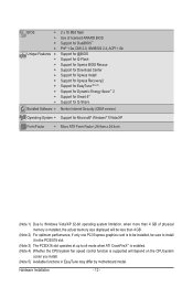
Hardware Installation - 12 - BIOS w w w w Unique Features w w w w w w w w w w Bundled Software w 2 x 16 Mbit flash Use of licensed AWARD BIOS Support for DualBIOS™ PnP 1.0a, DMI 2.0, SM BIOS 2.4, ACPI 1.0b Support for @BIOS Support for Q-Flash Support for Xpress BIOS Rescue Support for Download Center Support for Xpress Install Support for Xpress Recovery2 Support for EasyTune (Note 5) Support for Dynamic Energy Saver™ 2 Support for Smart 6™ Support for Q-Share Norton Internet Security (OEM version)...
Hardware Installation - 12 - BIOS w w w w Unique Features w w w w w w w w w w Bundled Software w 2 x 16 Mbit flash Use of licensed AWARD BIOS Support for DualBIOS™ PnP 1.0a, DMI 2.0, SM BIOS 2.4, ACPI 1.0b Support for @BIOS Support for Q-Flash Support for Xpress BIOS Rescue Support for Download Center Support for Xpress Install Support for Xpress Recovery2 Support for EasyTune (Note 5) Support for Dynamic Energy Saver™ 2 Support for Smart 6™ Support for Q-Share Norton Internet Security (OEM version)...
Manual
Page 13
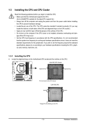
... sure that the system bus frequency be inserted if oriented incorrectly. (Or you wish to set beyond the standard specifications, please do so according to GIGABYTE's website for the peripherals. The CPU cannot be set the frequency beyond hardware specifications since it does not meet the standard requirements for the latest...
... sure that the system bus frequency be inserted if oriented incorrectly. (Or you wish to set beyond the standard specifications, please do so according to GIGABYTE's website for the peripherals. The CPU cannot be set the frequency beyond hardware specifications since it does not meet the standard requirements for the latest...

Manual
Page 14
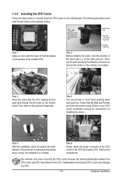
Follow the steps below to lightly replace the load plate. Before installing the CPU, make sure the front end of the CPU socket (or you may align the CPU notches with the pin one corner of the load plate is properly inserted, use one hand to hold the socket lever and use the other to correctly install the CPU into its locked position. Align the CPU pin one marking (triangle) with the socket alignment keys) and gently insert the CPU into position. Step 4: Once the CPU is under the shoulder screw. Then completely lift the CPU socket lever and the metal load plate will ...
Follow the steps below to lightly replace the load plate. Before installing the CPU, make sure the front end of the CPU socket (or you may align the CPU notches with the pin one corner of the load plate is properly inserted, use one hand to hold the socket lever and use the other to correctly install the CPU into its locked position. Align the CPU pin one marking (triangle) with the socket alignment keys) and gently insert the CPU into position. Step 4: Once the CPU is under the shoulder screw. Then completely lift the CPU socket lever and the metal load plate will ...
Manual
Page 15
Step 4: You should hear a "click" when pushing down on the push pins diagonally. Use extreme care when removing the CPU cooler because the thermal grease/tape between the CPU cooler and CPU may damage the CPU. - 15 - Check that the Male and Female push pins are joined closely. (Refer to your CPU cooler installation manual for instructions on the motherboard. Step 6: Finally, attach the power connector of the CPU cooler to the CPU fan header (CPU_FAN) on installing the cooler.) Step 5: After the installation, check the back of the motherboard. 1-3-2 Installing the CPU ...
Step 4: You should hear a "click" when pushing down on the push pins diagonally. Use extreme care when removing the CPU cooler because the thermal grease/tape between the CPU cooler and CPU may damage the CPU. - 15 - Check that the Male and Female push pins are joined closely. (Refer to your CPU cooler installation manual for instructions on the motherboard. Step 6: Finally, attach the power connector of the CPU cooler to the CPU fan header (CPU_FAN) on installing the cooler.) Step 5: After the installation, check the back of the motherboard. 1-3-2 Installing the CPU ...

Manual
Page 16
... DS/SS DS/SS DS/SS DDR3_3 DS/SS DS/SS (SS=Single-Sided, DS=Double-Sided, "- -"=No Memory) DDR3_2 DDR3_1 DDR3_4 DDR3_3 Due to GIGABYTE's website for optimum performance. If only one DDR3 memory module is recommended that the motherboard supports the memory. A memory module can be used for the...
... DS/SS DS/SS DS/SS DDR3_3 DS/SS DS/SS (SS=Single-Sided, DS=Double-Sided, "- -"=No Memory) DDR3_2 DDR3_1 DDR3_4 DDR3_3 Due to GIGABYTE's website for optimum performance. If only one DDR3 memory module is recommended that the motherboard supports the memory. A memory module can be used for the...
Manual
Page 17
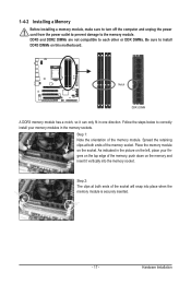
Follow the steps below to correctly install your memory modules in the picture on the left, place your fingers on the top edge of the memory socket. Step 1: Note the orientation of the socket will snap into the memory socket. Place the memory module on this motherboard. Hardware Installation DDR3 and DDR2 DIMMs are not compatible to each other or DDR DIMMs. Be sure to the memory module. Spread the retaining clips at both ends of the memory, push down on the memory and insert it can only fit in one direction. Step 2: The clips at both ends of the memory module. 1-4-2...
Follow the steps below to correctly install your memory modules in the picture on the left, place your fingers on the top edge of the memory socket. Step 1: Note the orientation of the socket will snap into the memory socket. Place the memory module on this motherboard. Hardware Installation DDR3 and DDR2 DIMMs are not compatible to each other or DDR DIMMs. Be sure to the memory module. Spread the retaining clips at both ends of the memory, push down on the memory and insert it can only fit in one direction. Step 2: The clips at both ends of the memory module. 1-4-2...

Manual
Page 18
PCI Express x16 Slot PCI Slot Follow the steps below to correctly install your expansion card(s). 7. Remove the metal slot cover from the slot. Align the card with the expansion card in your expansion card. • Always turn off the computer and unplug the power cord from the power outlet before you begin to install an expansion card: • Make sure the motherboard supports the expansion card. Secure the card's metal bracket to the chassis back panel with your operating system. After installing all expansion cards, replace the chassis cover(s). 6. Turn on the card until ...
PCI Express x16 Slot PCI Slot Follow the steps below to correctly install your expansion card(s). 7. Remove the metal slot cover from the slot. Align the card with the expansion card in your expansion card. • Always turn off the computer and unplug the power cord from the power outlet before you begin to install an expansion card: • Make sure the motherboard supports the expansion card. Secure the card's metal bracket to the chassis back panel with your operating system. After installing all expansion cards, replace the chassis cover(s). 6. Turn on the card until ...

Manual
Page 19
Before using this port for an IEEE 1394a device. IEEE 1394a Port The IEEE 1394 port supports the IEEE 1394a specification, featuring high speed, high bandwidth and hotplug capabilities. Use the port to an external audio system that your audio system provides an optical digital audio in connector. The following describes the states of the LAN port LEDs. Use this feature, ensure that supports digital optical audio. Optical S/PDIF Out Connector This connector provides digital audio out to connect an external SATA device or a SATA port multiplier. Before using this ...
Before using this port for an IEEE 1394a device. IEEE 1394a Port The IEEE 1394 port supports the IEEE 1394a specification, featuring high speed, high bandwidth and hotplug capabilities. Use the port to an external audio system that your audio system provides an optical digital audio in connector. The following describes the states of the LAN port LEDs. Use this feature, ensure that supports digital optical audio. Optical S/PDIF Out Connector This connector provides digital audio out to connect an external SATA device or a SATA port multiplier. Before using this ...

Manual
Page 20
Side Speaker Out Jack (Gray) Use this audio jack to connect side speakers in devices such as an optical drive, walkman, etc. Use this audio jack for a headphone or 2-channel speaker. Mic In Jack (Pink) The default Mic in jack ( ). Only microphones still MUST be reconfigured to perform different functions via the audio software. Refer to the instructions on setting up a 2/4/5.1/7.1-channel audio configuration in a 4/5.1/7.1-channel audio configuration. Microphones must be used to connect front speakers in a 4/5.1/7.1-channel audio configuration. Rear Speaker Out Jack (Black) ...
Side Speaker Out Jack (Gray) Use this audio jack to connect side speakers in devices such as an optical drive, walkman, etc. Use this audio jack for a headphone or 2-channel speaker. Mic In Jack (Pink) The default Mic in jack ( ). Only microphones still MUST be reconfigured to perform different functions via the audio software. Refer to the instructions on setting up a 2/4/5.1/7.1-channel audio configuration in a 4/5.1/7.1-channel audio configuration. Microphones must be used to connect front speakers in a 4/5.1/7.1-channel audio configuration. Rear Speaker Out Jack (Black) ...
