
Manual
Page 1
.... Before installing the operating system, you can go to the Application Software screen to individually install the X.H.D utility later. eXtreme Hard Drive (X.H.D) With GIGABYTE eXtreme Hard Drive (X.H.D)(Note 1), users can use X.H.D to easily add a hard drive into a RAID 0 array that before you can build a ..., back up a RAID array: (Note 3): Click Manual to access the Intel Matrix Storage Console, with a simple click of a button, X.H.D helps to enhance your data to the biggest drive in the Intel Chipset. (Note 2) It is added. Step 2: Install the RAID driver and operating ...
.... Before installing the operating system, you can go to the Application Software screen to individually install the X.H.D utility later. eXtreme Hard Drive (X.H.D) With GIGABYTE eXtreme Hard Drive (X.H.D)(Note 1), users can use X.H.D to easily add a hard drive into a RAID 0 array that before you can build a ..., back up a RAID array: (Note 3): Click Manual to access the Intel Matrix Storage Console, with a simple click of a button, X.H.D helps to enhance your data to the biggest drive in the Intel Chipset. (Note 2) It is added. Step 2: Install the RAID driver and operating ...

Manual
Page 3
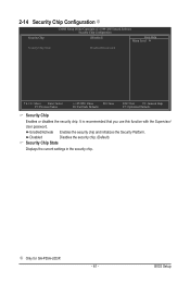
...appear. CMOS Setup Utility-Copyright (C) 1984-2009 Award Software Security Chip Configuration Security Chip Clear Security Chip [Enabled/Activate] [Enter] Item Help Menu Level Security Chip State Enabled/Activated Move Enter: Select F5: Previous Values +/-/PU/PD: Value F10: Save F6: ...Fail-Safe Defaults ESC: Exit F1: General Help F7: Optimized Defaults Step 2: After completing the settings, press to the Security Chip Configuration menu and the following screen will become ...
...appear. CMOS Setup Utility-Copyright (C) 1984-2009 Award Software Security Chip Configuration Security Chip Clear Security Chip [Enabled/Activate] [Enter] Item Help Menu Level Security Chip State Enabled/Activated Move Enter: Select F5: Previous Values +/-/PU/PD: Value F10: Save F6: ...Fail-Safe Defaults ESC: Exit F1: General Help F7: Optimized Defaults Step 2: After completing the settings, press to the Security Chip Configuration menu and the following screen will become ...
Manual
Page 35
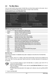
... its defaults. • The BIOS Setup menus described in this chapter are for GA-P55A-UD3P. - 35 - Use arrow keys to move among the items and press to accept or enter a sub-menu. (Sample BIOS Version: GA-P55A-UD3P D12) CMOS Setup Utility-Copyright (C) 1984-2009 Award Software MB Intelligent ...numeric value or make changes Decrease the numeric value or make changes Show descriptions of the function keys Move cursor to the Item Help block on the right (submenus only) Restore the previous BIOS settings for the current submenus Load the Fail-Safe BIOS default ...
... its defaults. • The BIOS Setup menus described in this chapter are for GA-P55A-UD3P. - 35 - Use arrow keys to move among the items and press to accept or enter a sub-menu. (Sample BIOS Version: GA-P55A-UD3P D12) CMOS Setup Utility-Copyright (C) 1984-2009 Award Software MB Intelligent ...numeric value or make changes Decrease the numeric value or make changes Show descriptions of the function keys Move cursor to the Item Help block on the right (submenus only) Restore the previous BIOS settings for the current submenus Load the Fail-Safe BIOS default ...
Manual
Page 37
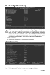
... } Advanced Memory Settings } Advanced Voltage Settings } Miscellaneous Settings [Press Enter] [Press Enter] [Press Enter] [Press Enter] [Press Enter] Item Help Menu Level BIOS Version BCLK CPU Frequency Memory Frequency Total Memory Size D12 136.73 MHz 2324.39 MHz 1367.34 MHz 2048 MB...Move Enter: Select F5: Previous Values +/-/PU/PD: Value F10: Save F6: Fail-Safe Defaults ESC: Exit F1: General Help F7: Optimized Defaults Whether the system will work stably with the overclock/overvoltage settings you made is for advanced users only and we...
... } Advanced Memory Settings } Advanced Voltage Settings } Miscellaneous Settings [Press Enter] [Press Enter] [Press Enter] [Press Enter] [Press Enter] Item Help Menu Level BIOS Version BCLK CPU Frequency Memory Frequency Total Memory Size D12 136.73 MHz 2324.39 MHz 1367.34 MHz 2048 MB...Move Enter: Select F5: Previous Values +/-/PU/PD: Value F10: Save F6: Fail-Safe Defaults ESC: Exit F1: General Help F7: Optimized Defaults Whether the system will work stably with the overclock/overvoltage settings you made is for advanced users only and we...
Manual
Page 38
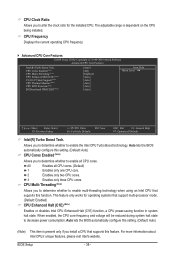
... Thermal Monitor (Note) CPU EIST Function (Note) Bi-Directional PROCHOT (Note) [Auto] [All] [Enabled] [Auto] [Auto] [Auto] [Auto] [Auto] Item Help Menu Level Move Enter: Select F5: Previous Values +/-/PU/PD: Value F10: Save F6: Fail-Safe Defaults ESC: Exit F1: General... Help F7: Optimized Defaults Intel(R) Turbo Boost Tech. BIOS Setup - 38 - CPU Frequency Displays the current operating CPU frequency. Advanced CPU...
... Thermal Monitor (Note) CPU EIST Function (Note) Bi-Directional PROCHOT (Note) [Auto] [All] [Enabled] [Auto] [Auto] [Auto] [Auto] [Auto] Item Help Menu Level Move Enter: Select F5: Previous Values +/-/PU/PD: Value F10: Save F6: Fail-Safe Defaults ESC: Exit F1: General... Help F7: Optimized Defaults Intel(R) Turbo Boost Tech. BIOS Setup - 38 - CPU Frequency Displays the current operating CPU frequency. Advanced CPU...

Manual
Page 41
... A } Channel A Timing Settings >>>>> Channel B } Channel B Timing Settings [Disabled] [Auto] 1333 [Turbo] [Auto] 1.5V 1.1V Auto Auto [Press Enter] [Press Enter] Item Help Menu Level Move Enter: Select F5: Previous Values +/-/PU/PD: Value F10: Save F6: Fail-Safe Defaults ESC: Exit F1: General... Help F7: Optimized Defaults Extreme Memory Profile (X.M.P.) (Note) Allows the BIOS to read the SPD data on XMP memory module(s) to enhance...
... A } Channel A Timing Settings >>>>> Channel B } Channel B Timing Settings [Disabled] [Auto] 1333 [Turbo] [Auto] 1.5V 1.1V Auto Auto [Press Enter] [Press Enter] Item Help Menu Level Move Enter: Select F5: Previous Values +/-/PU/PD: Value F10: Save F6: Fail-Safe Defaults ESC: Exit F1: General... Help F7: Optimized Defaults Extreme Memory Profile (X.M.P.) (Note) Allows the BIOS to read the SPD data on XMP memory module(s) to enhance...

Manual
Page 42
... as 1.5V. x Round Trip Latency 36 Auto Auto Auto Auto Auto Auto Auto Auto Auto Auto Auto Auto Auto Auto Auto Auto Item Help Menu Level Move Enter: Select F5: Previous Values +/-/PU/PD: Value F10: Save F6: Fail-Safe Defaults ESC: ...Exit F1: General Help F7: Optimized Defaults >>>>> Channel A/B Standard Timing Control CAS Latency Time Options are : Auto (default), 1~7. tRRD Options are : Auto (default), 6~15. Rank ...
... as 1.5V. x Round Trip Latency 36 Auto Auto Auto Auto Auto Auto Auto Auto Auto Auto Auto Auto Auto Auto Auto Auto Item Help Menu Level Move Enter: Select F5: Previous Values +/-/PU/PD: Value F10: Save F6: Fail-Safe Defaults ESC: ...Exit F1: General Help F7: Optimized Defaults >>>>> Channel A/B Standard Timing Control CAS Latency Time Options are : Auto (default), 1~7. tRRD Options are : Auto (default), 6~15. Rank ...

Manual
Page 43
...] DRAM Termination 0.750V [Auto] Ch-A Data VRef. 0.750V [Auto] Ch-B Data VRef. 0.750V [Auto] Ch-A Address VRef. 0.750V [Auto] Ch-B Address VRef. 0.750V [Auto] Item Help Menu Level Move Enter: Select F5: Previous Values +/-/PU/PD: Value F10: Save F6: Fail-Safe Defaults ESC: Exit F1: General...
...] DRAM Termination 0.750V [Auto] Ch-A Data VRef. 0.750V [Auto] Ch-B Data VRef. 0.750V [Auto] Ch-A Address VRef. 0.750V [Auto] Ch-B Address VRef. 0.750V [Auto] Item Help Menu Level Move Enter: Select F5: Previous Values +/-/PU/PD: Value F10: Save F6: Fail-Safe Defaults ESC: Exit F1: General...
Manual
Page 45
... Memory Settings } Advanced Voltage Settings } Miscellaneous Settings [Press Enter] [Press Enter] [Press Enter] [Press Enter] [Press Enter] Item Help Menu Level BIOS Version BCLK CPU Frequency Memory Frequency Total Memory Size D12 136.73 MHz 2324.39 MHz 1367.34 MHz 2048 MB...584V Move Enter: Select F5: Previous Values +/-/PU/PD: Value F10: Save F6: Fail-Safe Defaults ESC: Exit F1: General Help F7: Optimized Defaults This section provides information on the BIOS version, CPU base clock, CPU frequency, memory frequency, total memory size ...
... Memory Settings } Advanced Voltage Settings } Miscellaneous Settings [Press Enter] [Press Enter] [Press Enter] [Press Enter] [Press Enter] Item Help Menu Level BIOS Version BCLK CPU Frequency Memory Frequency Total Memory Size D12 136.73 MHz 2324.39 MHz 1367.34 MHz 2048 MB...584V Move Enter: Select F5: Previous Values +/-/PU/PD: Value F10: Save F6: Fail-Safe Defaults ESC: Exit F1: General Help F7: Optimized Defaults This section provides information on the BIOS version, CPU base clock, CPU frequency, memory frequency, total memory size ...
Manual
Page 46
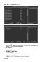
...-Copyright (C) 1984-2009 Award Software Standard CMOS Features Date (mm:dd:yy) Time (hh:mm:ss) Wed, Sep 23 2009 22:31:24 Item Help Menu Level } IDE Channel 0 Master } IDE Channel 0 Slave } IDE Channel 1 Master } IDE Channel 1 Slave } IDE Channel 2...44M, 3.5"] Move Enter: Select F5: Previous Values +/-/PU/PD: Value F10: Save F6: Fail-Safe Defaults ESC: Exit F1: General Help F7: Optimized Defaults CMOS Setup Utility-Copyright (C) 1984-2009 Award Software Standard CMOS Features Halt On Base Memory Extended Memory Total Memory [All,...
...-Copyright (C) 1984-2009 Award Software Standard CMOS Features Date (mm:dd:yy) Time (hh:mm:ss) Wed, Sep 23 2009 22:31:24 Item Help Menu Level } IDE Channel 0 Master } IDE Channel 0 Slave } IDE Channel 1 Master } IDE Channel 1 Slave } IDE Channel 2...44M, 3.5"] Move Enter: Select F5: Previous Values +/-/PU/PD: Value F10: Save F6: Fail-Safe Defaults ESC: Exit F1: General Help F7: Optimized Defaults CMOS Setup Utility-Copyright (C) 1984-2009 Award Software Standard CMOS Features Halt On Base Memory Extended Memory Total Memory [All,...

Manual
Page 48
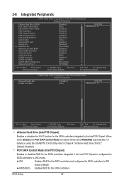
...Press to HDD Init Display First [Press Enter] [Disabled] [Hard Disk] [CDROM] [Floppy] [Setup] [Disabled] [Disabled] [Enabled] [0] [Enabled] [Disabled] [PCI] Item Help Menu Level Move Enter: Select F5: Previous Values +/-/PU/PD: Value F10: Save F6: Fail-Safe Defaults ESC: Exit F1: General... Help F7: Optimized Defaults Hard Disk Boot Priority Specifies the sequence of loading the operating system from the available devices. The settings here ...
...Press to HDD Init Display First [Press Enter] [Disabled] [Hard Disk] [CDROM] [Floppy] [Setup] [Disabled] [Disabled] [Enabled] [0] [Enabled] [Disabled] [PCI] Item Help Menu Level Move Enter: Select F5: Previous Values +/-/PU/PD: Value F10: Save F6: Fail-Safe Defaults ESC: Exit F1: General... Help F7: Optimized Defaults Hard Disk Boot Priority Specifies the sequence of loading the operating system from the available devices. The settings here ...
Manual
Page 50
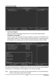
For details on using the GIGABYTE X.H.D utility, refer to Chaper 4, "eXtreme Hard Drive (X.H.D)." (Default: Disabled...Auto] [Enabled] [Disabled] [Press Enter] [Disabled] [Enabled] [Enabled] [IDE] [Enabled] [IDE] [Press Enter] [3F8/IRQ4] Item Help Menu Level Move Enter: Select F5: Previous Values +/-/PU/PD: Value F10: Save F6: Fail-Safe Defaults ESC: Exit F1: General...Previous Values +/-/PU/PD: Value F10: Save F6: Fail-Safe Defaults ESC: Exit F1: General Help F7: Optimized Defaults eXtreme Hard Drive (Intel P55 Chipset) Enables or disables the X.H.D function for the...
For details on using the GIGABYTE X.H.D utility, refer to Chaper 4, "eXtreme Hard Drive (X.H.D)." (Default: Disabled...Auto] [Enabled] [Disabled] [Press Enter] [Disabled] [Enabled] [Enabled] [IDE] [Enabled] [IDE] [Press Enter] [3F8/IRQ4] Item Help Menu Level Move Enter: Select F5: Previous Values +/-/PU/PD: Value F10: Save F6: Fail-Safe Defaults ESC: Exit F1: General...Previous Values +/-/PU/PD: Value F10: Save F6: Fail-Safe Defaults ESC: Exit F1: General Help F7: Optimized Defaults eXtreme Hard Drive (Intel P55 Chipset) Enables or disables the X.H.D function for the...

Manual
Page 52
... Part1-2 Status = Open / Length = 0m Part3-6 Status = Open / Length = 0m Part4-5 Status = Open / Length = 0m Part7-8 Status = Open / Length = 0m Item Help Menu Level Move Enter: Select F5: Previous Values +/-/PU/PD: Value F10: Save F6: Fail-Safe Defaults ESC: Exit F1: General... Help F7: Optimized Defaults This motherboard incorporates cable diagnostic feature designed to the fault or short. This feature will be the approximate distance to...
... Part1-2 Status = Open / Length = 0m Part3-6 Status = Open / Length = 0m Part4-5 Status = Open / Length = 0m Part7-8 Status = Open / Length = 0m Item Help Menu Level Move Enter: Select F5: Previous Values +/-/PU/PD: Value F10: Save F6: Fail-Safe Defaults ESC: Exit F1: General... Help F7: Optimized Defaults This motherboard incorporates cable diagnostic feature designed to the fault or short. This feature will be the approximate distance to...

Manual
Page 54
... Password AC Back Function EuP Support [S3(STR)] [Instant-Off] [Enabled] [Enabled] [Disabled] Everyday 0 : 0 : 0 [Enabled] [32-bit mode] [Disabled] [Disabled] Enter [Soft-Off] [Disabled] Item Help Menu Level Move Enter: Select F5: Previous Values +/-/PU/PD: Value F10: Save F6: Fail-Safe Defaults ESC: Exit F1: General...
... Password AC Back Function EuP Support [S3(STR)] [Instant-Off] [Enabled] [Enabled] [Disabled] Everyday 0 : 0 : 0 [Enabled] [32-bit mode] [Disabled] [Disabled] Enter [Soft-Off] [Disabled] Item Help Menu Level Move Enter: Select F5: Previous Values +/-/PU/PD: Value F10: Save F6: Fail-Safe Defaults ESC: Exit F1: General...

Manual
Page 56
... [Disabled] No 1.220V 1.504V 4.972V 12.048V 30oC 47oC 3375 RPM 0 RPM 0 RPM 0 RPM [Disabled] [Disabled] [Disabled] [Disabled] [Disabled] [Enabled] [Auto] Item Help Menu Level Move Enter: Select F5: Previous Values +/-/PU/PD: Value F10: Save F6: Fail-Safe Defaults ESC: Exit F1: General... Help F7: Optimized Defaults Reset Case Open Status Keeps or clears the record of the chassis intrusion detection device attached to the motherboard CI header....
... [Disabled] No 1.220V 1.504V 4.972V 12.048V 30oC 47oC 3375 RPM 0 RPM 0 RPM 0 RPM [Disabled] [Disabled] [Disabled] [Disabled] [Disabled] [Enabled] [Auto] Item Help Menu Level Move Enter: Select F5: Previous Values +/-/PU/PD: Value F10: Save F6: Fail-Safe Defaults ESC: Exit F1: General... Help F7: Optimized Defaults Reset Case Open Status Keeps or clears the record of the chassis intrusion detection device attached to the motherboard CI header....
Manual
Page 58
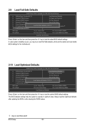
The BIOS defaults settings help the system to operate in optimum state. BIOS Setup - 58 - j Only for the motherboard. 2-10 Load Optimized Defaults CMOS Setup Utility-Copyright (C) 1984-2009 Award ... default settings. In case system instability occurs, you may try to load Fail-Safe defaults, which are the safest and most stable BIOS settings for GA-P55A-UD3P. Always load the Optimized defaults after updating the BIOS or after clearing the CMOS values. 2-9 Load Fail-Safe Defaults CMOS Setup Utility-Copyright (C) 1984-2009...
The BIOS defaults settings help the system to operate in optimum state. BIOS Setup - 58 - j Only for the motherboard. 2-10 Load Optimized Defaults CMOS Setup Utility-Copyright (C) 1984-2009 Award ... default settings. In case system instability occurs, you may try to load Fail-Safe defaults, which are the safest and most stable BIOS settings for GA-P55A-UD3P. Always load the Optimized defaults after updating the BIOS or after clearing the CMOS values. 2-9 Load Fail-Safe Defaults CMOS Setup Utility-Copyright (C) 1984-2009...
Manual
Page 61
... Enter: Select F5: Previous Values +/-/PU/PD: Value F10: Save F6: Fail-Safe Defaults ESC: Exit F1: General Help F7: Optimized Defaults Security Chip Enables or disables the security chip. j Only for GA-P55A-UD3P. - 61 - BIOS Setup Enabled/Activate Enables the security chip and initializes the Security Platform. It is recommended that you...
... Enter: Select F5: Previous Values +/-/PU/PD: Value F10: Save F6: Fail-Safe Defaults ESC: Exit F1: General Help F7: Optimized Defaults Security Chip Enables or disables the security chip. j Only for GA-P55A-UD3P. - 61 - BIOS Setup Enabled/Activate Enables the security chip and initializes the Security Platform. It is recommended that you...

Manual
Page 73
In Windows, close all applications and TSR (Terminate and Stay Resident) programs. This helps prevent unexpected failures when performing a BIOS update. 2. During the BIOS update process, ensure the Internet connection is unable to start. 3. B. Using @BIOS ...restarts. Unique Features Failure to do NOT interrupt the Internet connection (for your motherboard is not present on -screen instructions to complete. 3. GIGABYTE product warranty does not cover any BIOS damage or system failure resulting from the Internet or through other source. Load BIOS Defaults after BIOS...
In Windows, close all applications and TSR (Terminate and Stay Resident) programs. This helps prevent unexpected failures when performing a BIOS update. 2. During the BIOS update process, ensure the Internet connection is unable to start. 3. B. Using @BIOS ...restarts. Unique Features Failure to do NOT interrupt the Internet connection (for your motherboard is not present on -screen instructions to complete. 3. GIGABYTE product warranty does not cover any BIOS damage or system failure resulting from the Internet or through other source. Load BIOS Defaults after BIOS...

Manual
Page 75
...5 76 1 8 9 15 11 16 10 Meter Mode - 4-4 Dynamic Energy Saver™ 2 GIGABYTE Dynamic Energy Saver™ 2 (Note 1) is for reference only. Featuring an advanced proprietary hardware and software design, GIGABYTE Dynamic Energy Saver™ 2 is able to run in power-saving mode will continue to provide exceptional... power savings and enhanced power efficiency without sacrificing computing performance. Meter Mode In Meter Mode, GIGABYTE Dynamic Energy Saver™ 2 shows how much power they have saved in a set period of the devices currently in taskbar) ...
...5 76 1 8 9 15 11 16 10 Meter Mode - 4-4 Dynamic Energy Saver™ 2 GIGABYTE Dynamic Energy Saver™ 2 (Note 1) is for reference only. Featuring an advanced proprietary hardware and software design, GIGABYTE Dynamic Energy Saver™ 2 is able to run in power-saving mode will continue to provide exceptional... power savings and enhanced power efficiency without sacrificing computing performance. Meter Mode In Meter Mode, GIGABYTE Dynamic Energy Saver™ 2 shows how much power they have saved in a set period of the devices currently in taskbar) ...

Manual
Page 76
... to reset to zero. (Note 4) Dynamic Energy Saver Meter will continue to see how much total power savings they have accumulated in taskbar) 13 INFO/Help 14 Motherboard Phase LED On/Off Switch (Default: On) 15 Live Utility Update (Check for the first time (Note 3). 11 12 13 3 2 4 65 1 7 8 14 10...
... to reset to zero. (Note 4) Dynamic Energy Saver Meter will continue to see how much total power savings they have accumulated in taskbar) 13 INFO/Help 14 Motherboard Phase LED On/Off Switch (Default: On) 15 Live Utility Update (Check for the first time (Note 3). 11 12 13 3 2 4 65 1 7 8 14 10...


