
Manual
Page 1
... Enabled to automatically install all of your hard drive read/write performance without the need for the Intel SATA controllers. You can click the Xpress Install All button to enable RAID for complex and time-consuming configurations. B. To manually set up a RAID array: (Note 3): Click Manual to individually install the X.H.D utility later. Step 2: Install the RAID driver and operating system The X.H.D utility supports Windows 7/Vista/XP. Or you can go to the Application Software screen...
... Enabled to automatically install all of your hard drive read/write performance without the need for the Intel SATA controllers. You can click the Xpress Install All button to enable RAID for complex and time-consuming configurations. B. To manually set up a RAID array: (Note 3): Click Manual to individually install the X.H.D utility later. Step 2: Install the RAID driver and operating system The X.H.D utility supports Windows 7/Vista/XP. Or you can go to the Application Software screen...

Manual
Page 3
... your motherboard revision before updating motherboard BIOS, drivers, or when looking for technical information. Check your motherboard looks like this manual may be made by GIGABYTE without GIGABYTE's prior written permission. No part of this product, GIGABYTE provides the following types of documentations: For quick set-up of GIGABYTE. Copyright © 2009 GIGA-BYTE TECHNOLOGY CO., LTD. For detailed product information, carefully read the Quick Installation Guide included...
... your motherboard revision before updating motherboard BIOS, drivers, or when looking for technical information. Check your motherboard looks like this manual may be made by GIGABYTE without GIGABYTE's prior written permission. No part of this product, GIGABYTE provides the following types of documentations: For quick set-up of GIGABYTE. Copyright © 2009 GIGA-BYTE TECHNOLOGY CO., LTD. For detailed product information, carefully read the Quick Installation Guide included...

Manual
Page 4
... SLI Configuration 19 1-7 Back Panel Connectors 20 1-8 Internal Connectors 22 Chapter 2 BIOS Setup 35 2-1 Startup Screen 36 2-2 The Main Menu 37 2-3 MB Intelligent Tweaker(M.I.T 39 2-4 Standard CMOS Features 49 2-5 Advanced BIOS Features 51 2-6 Integrated Peripherals 53 2-7 Power Management Setup 57 2-8 PC Health Status 59 2-9 Load Fail-Safe Defaults 61 2-10 Load Optimized Defaults 61 2-11 Set Supervisor/User Password 62 2-12 Save & Exit Setup 63 2-13 Exit Without Saving 63 2-14 Security Chip Configuration j 64 Chapter 3 Drivers Installation...
... SLI Configuration 19 1-7 Back Panel Connectors 20 1-8 Internal Connectors 22 Chapter 2 BIOS Setup 35 2-1 Startup Screen 36 2-2 The Main Menu 37 2-3 MB Intelligent Tweaker(M.I.T 39 2-4 Standard CMOS Features 49 2-5 Advanced BIOS Features 51 2-6 Integrated Peripherals 53 2-7 Power Management Setup 57 2-8 PC Health Status 59 2-9 Load Fail-Safe Defaults 61 2-10 Load Optimized Defaults 61 2-11 Set Supervisor/User Password 62 2-12 Save & Exit Setup 63 2-13 Exit Without Saving 63 2-14 Security Chip Configuration j 64 Chapter 3 Drivers Installation...

Manual
Page 10
...x PCI slots Multi-Graphics Support for ATI CrossFireX™/NVIDIA SLI technology Technology Storage Interface Intel® P55 Express Chipset: - 6 x SATA 3Gb/s connectors (SATA2_0, SATA2_1, SATA2_2, SATA2_3, SATA2_4, SATA2_5) supporting up to 1 floppy disk drive j Only for GA-P55-UD4P. k Only for SATA RAID 0, RAID 1, and JBOD JMB362 SATA2 chip: - 2 x eSATA 3Gb/s connectors on the back panel supporting up to 2 SATA 3Gb/s devices - Hardware Installation - 10 - Support for SATA RAID 0, RAID 1, RAID...
...x PCI slots Multi-Graphics Support for ATI CrossFireX™/NVIDIA SLI technology Technology Storage Interface Intel® P55 Express Chipset: - 6 x SATA 3Gb/s connectors (SATA2_0, SATA2_1, SATA2_2, SATA2_3, SATA2_4, SATA2_5) supporting up to 1 floppy disk drive j Only for GA-P55-UD4P. k Only for SATA RAID 0, RAID 1, and JBOD JMB362 SATA2 chip: - 2 x eSATA 3Gb/s connectors on the back panel supporting up to 2 SATA 3Gb/s devices - Hardware Installation - 10 - Support for SATA RAID 0, RAID 1, RAID...

Manual
Page 11
... 14 USB 2.0/1.1 ports (10 on the back panel, 1 via the USB brackets connected to the internal IEEE 1394a header) 1 x 24-pin ATX main power connector 1 x 8-pin ATX 12V power connector 1 x floppy disk drive connector 1 x IDE connector 8 x SATA 3Gb/s connectors 1 x CPU fan header 2 x system fan headers 1 x power fan header 1 x PCH chip fan header 1 x front panel header 1 x front panel audio header 1 x CD In connector 1 x S/PDIF In header 1 x S/PDIF Out header 2 x USB 2.0/1.1 headers 1 x IEEE 1394a header 1 x serial port header 1 x parallel port header 1 x clearing CMOS jumper 1 x PS/2 keyboard...
... 14 USB 2.0/1.1 ports (10 on the back panel, 1 via the USB brackets connected to the internal IEEE 1394a header) 1 x 24-pin ATX main power connector 1 x 8-pin ATX 12V power connector 1 x floppy disk drive connector 1 x IDE connector 8 x SATA 3Gb/s connectors 1 x CPU fan header 2 x system fan headers 1 x power fan header 1 x PCH chip fan header 1 x front panel header 1 x front panel audio header 1 x CD In connector 1 x S/PDIF In header 1 x S/PDIF Out header 2 x USB 2.0/1.1 headers 1 x IEEE 1394a header 1 x serial port header 1 x parallel port header 1 x clearing CMOS jumper 1 x PS/2 keyboard...

Manual
Page 18
... slot cover from the slot. Secure the card's metal bracket to make any required BIOS changes for your operating system. If necessary, go to BIOS Setup to the chassis back panel with the slot, and press down on the card are completely inserted into the PCI Express slot. 1-5 Installing an Expansion Card Read the following guidelines before installing an expansion card to install an expansion card: • Make sure the motherboard supports...
... slot cover from the slot. Secure the card's metal bracket to make any required BIOS changes for your operating system. If necessary, go to BIOS Setup to the chassis back panel with the slot, and press down on the card are completely inserted into the PCI Express slot. 1-5 Installing an Expansion Card Read the following guidelines before installing an expansion card to install an expansion card: • Make sure the motherboard supports...

Manual
Page 19
.../SLI-supported motherboard with your graphics cards for more information about enabling CrossFireX/SLI technology. - 19 - Connecting the Graphics Cards Step 1: Observe the steps in the CrossFireX/SLI gold edge connectors on your graphics cards for enabling CrossFireX/SLI technology may be needed or not depending on top of your graphics cards. Step 3: Plug the display cable into the graphics card on the PCI Express x16 slots. Procedure and driver screen for the power requirement) B. Step 2: Insert the CrossFire (Note)/SLI bridge connectors...
.../SLI-supported motherboard with your graphics cards for more information about enabling CrossFireX/SLI technology. - 19 - Connecting the Graphics Cards Step 1: Observe the steps in the CrossFireX/SLI gold edge connectors on your graphics cards for enabling CrossFireX/SLI technology may be needed or not depending on top of your graphics cards. Step 3: Plug the display cable into the graphics card on the PCI Express x16 slots. Procedure and driver screen for the power requirement) B. Step 2: Insert the CrossFire (Note)/SLI bridge connectors...

Manual
Page 38
... default profile name, use this function to load the BIOS settings from a profile created before, without the hassles of errors that stop the system boot, etc. Advanced BIOS Features Use this menu to configure the device boot order, advanced features available on the CPU, and the primary display adapter. Integrated Peripherals Use this menu to configure all peripheral devices, such as IDE, SATA, USB, integrated audio, and integrated LAN, etc. Power Management Setup Use...
... default profile name, use this function to load the BIOS settings from a profile created before, without the hassles of errors that stop the system boot, etc. Advanced BIOS Features Use this menu to configure the device boot order, advanced features available on the CPU, and the primary display adapter. Integrated Peripherals Use this menu to configure all peripheral devices, such as IDE, SATA, USB, integrated audio, and integrated LAN, etc. Power Management Setup Use...

Manual
Page 41
... link speed. Auto lets the BIOS automatically configure this setting. (Default: Auto) Bi-Directional PROCHOT (Note) Auto Lets BIOS automatically configure this setting. (Default) Enabled When the CPU or chipset detects that supports this feature. When enabled, the CPU core frequency and voltage will be reduced when the CPU is a more information about Intel CPUs' unique features, please visit Intel's website. - 41 - Depending on CPU loading, Intel EIST technology can function as multiple virtual systems. (Default: Enabled) QPI Clock...
... link speed. Auto lets the BIOS automatically configure this setting. (Default: Auto) Bi-Directional PROCHOT (Note) Auto Lets BIOS automatically configure this setting. (Default) Enabled When the CPU or chipset detects that supports this feature. When enabled, the CPU core frequency and voltage will be reduced when the CPU is a more information about Intel CPUs' unique features, please visit Intel's website. - 41 - Depending on CPU loading, Intel EIST technology can function as multiple virtual systems. (Default: Enabled) QPI Clock...

Manual
Page 48
... the CPU and Chipset. (Default: Enabled) CMOS Setup Utility-Copyright (C) 1984-2009 Award Software MB Intelligent Tweaker(M.I.T.) } M.I.T Current Status } Advanced Frequency Settings } Advanced Memory Settings } Advanced Voltage Settings } Miscellaneous Settings [Press Enter] [Press Enter] [Press Enter] [Press Enter] [Press Enter] Item Help Menu Level BIOS Version BCLK CPU Frequency Memory Frequency Total Memory Size D38 133.27 MHz 3198.42 MHz 1332.80 MHz 1024 MB CPU Temperature PCH Temperature 45oC 40oC Vcore DRAM Voltage...
... the CPU and Chipset. (Default: Enabled) CMOS Setup Utility-Copyright (C) 1984-2009 Award Software MB Intelligent Tweaker(M.I.T.) } M.I.T Current Status } Advanced Frequency Settings } Advanced Memory Settings } Advanced Voltage Settings } Miscellaneous Settings [Press Enter] [Press Enter] [Press Enter] [Press Enter] [Press Enter] Item Help Menu Level BIOS Version BCLK CPU Frequency Memory Frequency Total Memory Size D38 133.27 MHz 3198.42 MHz 1332.80 MHz 1024 MB CPU Temperature PCH Temperature 45oC 40oC Vcore DRAM Voltage...

Manual
Page 51
.... Options are: Floppy, LS120, Hard Disk, CDROM, ZIP, USB-FDD, USB-ZIP, USB-CDROM, USB-HDD, Legacy LAN, Disabled. Setup A password is only required for entering the BIOS Setup program. (Default) System A password is required for booting the system and for daily use. HDD S.M.A.R.T. This feature allows your hard drive. 2-5 Advanced BIOS Features CMOS Setup Utility-Copyright (C) 1984-2009 Award Software Advanced BIOS Features } Hard Disk Boot Priority Quick Boot First Boot Device Second Boot Device Third Boot Device Password Check HDD S.M.A.R.T. The settings...
.... Options are: Floppy, LS120, Hard Disk, CDROM, ZIP, USB-FDD, USB-ZIP, USB-CDROM, USB-HDD, Legacy LAN, Disabled. Setup A password is only required for entering the BIOS Setup program. (Default) System A password is required for booting the system and for daily use. HDD S.M.A.R.T. This feature allows your hard drive. 2-5 Advanced BIOS Features CMOS Setup Utility-Copyright (C) 1984-2009 Award Software Advanced BIOS Features } Hard Disk Boot Priority Quick Boot First Boot Device Second Boot Device Third Boot Device Password Check HDD S.M.A.R.T. The settings...

Manual
Page 53
...Setup Utility-Copyright (C) 1984-2009 Award Software Integrated Peripherals SATA RAID/AHCI Mode SATA Port0-3 Native Mode USB Controllers USB Legacy Function USB Storage Function Azalia Codec Onboard H/W 1394 Onboard H/W LAN1 Onboard H/W LAN2 j Green LAN } SMART LAN1 } SMART LAN2 j Onboard LAN1 Boot ROM Onboard LAN2 Boot ROM j eSATA Controller eSATA Ctrl Mode GSATA 0_1/IDE Controller GSATA 0_1/IDE Ctrl Mode Onboard Serial Port 1 [Disabled] [Enabled] [Enabled] [Enabled] [Enabled] [Auto] [Enabled] [Enabled] [Enabled] [Disabled] [Press Enter...
...Setup Utility-Copyright (C) 1984-2009 Award Software Integrated Peripherals SATA RAID/AHCI Mode SATA Port0-3 Native Mode USB Controllers USB Legacy Function USB Storage Function Azalia Codec Onboard H/W 1394 Onboard H/W LAN1 Onboard H/W LAN2 j Green LAN } SMART LAN1 } SMART LAN2 j Onboard LAN1 Boot ROM Onboard LAN2 Boot ROM j eSATA Controller eSATA Ctrl Mode GSATA 0_1/IDE Controller GSATA 0_1/IDE Ctrl Mode Onboard Serial Port 1 [Disabled] [Enabled] [Enabled] [Enabled] [Enabled] [Auto] [Enabled] [Enabled] [Enabled] [Disabled] [Press Enter...

Manual
Page 56
...the SATA controller to AHCI mode. Options are: Auto, 3F8/IRQ4 (default), 2F8/IRQ3, 3E8/IRQ4, 2E8/IRQ3, Disabled. IDE Disables RAID for the SATA controller and configures the SATA controller to IDE mode. (Default) AHCI Configures the SATA controller to AHCI mode. GSATA 0_1/IDE Controller (GIGABYTE SATA2, IDE and GSATA2_0/1 Connectors) Enables or disables the IDE and SATA controllers integrated in the GIGABYTE SATA2 chip. (Default: Enabled) GSATA 0_1/IDE Ctrl Mode (GIGABYTE SATA2, IDE and GSATA2_0/1 Connectors) Enables or disables RAID for the onboard parallel (LPT) port...
...the SATA controller to AHCI mode. Options are: Auto, 3F8/IRQ4 (default), 2F8/IRQ3, 3E8/IRQ4, 2E8/IRQ3, Disabled. IDE Disables RAID for the SATA controller and configures the SATA controller to IDE mode. (Default) AHCI Configures the SATA controller to AHCI mode. GSATA 0_1/IDE Controller (GIGABYTE SATA2, IDE and GSATA2_0/1 Connectors) Enables or disables the IDE and SATA controllers integrated in the GIGABYTE SATA2 chip. (Default: Enabled) GSATA 0_1/IDE Ctrl Mode (GIGABYTE SATA2, IDE and GSATA2_0/1 Connectors) Enables or disables RAID for the onboard parallel (LPT) port...

Manual
Page 59
.../power fan speed. BIOS Setup When CPU temperature exceeds the threshold, BIOS will show "No". To clear the chassis intrusion status record, set Reset Case Open Status to Enabled, save the settings to the CPU temperature. Current Voltage(V) Vcore/DDR15V/+5V/+12V Displays the current system voltages. CPU/SYSTEM/POWER FAN Fail Warning Allows the system to the motherboard CI header. If the system chassis cover is not connected or fails. CPU Warning Temperature Sets the warning threshold for CPU temperature. Options are: Disabled (default...
.../power fan speed. BIOS Setup When CPU temperature exceeds the threshold, BIOS will show "No". To clear the chassis intrusion status record, set Reset Case Open Status to Enabled, save the settings to the CPU temperature. Current Voltage(V) Vcore/DDR15V/+5V/+12V Displays the current system voltages. CPU/SYSTEM/POWER FAN Fail Warning Allows the system to the motherboard CI header. If the system chassis cover is not connected or fails. CPU Warning Temperature Sets the warning threshold for CPU temperature. Options are: Disabled (default...

Manual
Page 83
... configurations. A. Instructions for using a Bluetooth cell phone or USB flash drive. Refer to the Infineon Security Platform Help file to see how to Enabled/Activate. Set Your TPM Password A password is not liable for GA-P55-UD4P. - 83 - Specify the PSD drive letter, drive label, size, and a local drive on the right of the autorun screen and you set Security Chip to set up the TPM User Password, configure a Personal Secure Drive, and create a portable user key...
... configurations. A. Instructions for using a Bluetooth cell phone or USB flash drive. Refer to the Infineon Security Platform Help file to see how to Enabled/Activate. Set Your TPM Password A password is not liable for GA-P55-UD4P. - 83 - Specify the PSD drive letter, drive label, size, and a local drive on the right of the autorun screen and you set Security Chip to set up the TPM User Password, configure a Personal Secure Drive, and create a portable user key...

Manual
Page 93
...RAID. In BIOS Setup, go to RAID/IDE CMOS Setup Utility-Copyright (C) 1984-2009 Award Software Integrated Peripherals SATA RAID/AHCI Mode SATA Port0-3 Native Mode USB Controllers USB Legacy Function USB Storage Function Azalia Codec Onboard H/W 1394 Onboard H/W LAN1 Onboard H/W LAN2 j Green LAN } SMART LAN1 } SMART LAN2 j Onboard LAN1 Boot ROM Onboard LAN2 Boot ROM j eSATA Controller eSATA Ctrl Mode GSATA 0_1/IDE Controller GSATA 0_1/IDE Ctrl Mode Onboard Serial Port 1 [Disabled] [Enabled] [Enabled] [Enabled] [Enabled] [Auto] [Enabled...
...RAID. In BIOS Setup, go to RAID/IDE CMOS Setup Utility-Copyright (C) 1984-2009 Award Software Integrated Peripherals SATA RAID/AHCI Mode SATA Port0-3 Native Mode USB Controllers USB Legacy Function USB Storage Function Azalia Codec Onboard H/W 1394 Onboard H/W LAN1 Onboard H/W LAN2 j Green LAN } SMART LAN1 } SMART LAN2 j Onboard LAN1 Boot ROM Onboard LAN2 Boot ROM j eSATA Controller eSATA Ctrl Mode GSATA 0_1/IDE Controller GSATA 0_1/IDE Ctrl Mode Onboard Serial Port 1 [Disabled] [Enabled] [Enabled] [Enabled] [Enabled] [Auto] [Enabled...

Manual
Page 99
... floppy disk. Steps: 1: Boot from the motherboard driver disk to that has CD-ROM support and a blank formatted floppy disk. Your system will open similar to a USB flash drive. First of all, copy the driver for the SATA controller from the menu and press . Without the driver, the hard drive may not be recognized during the OS installation. Select the controller driver by pressing the corresponding letter from the motherboard driver disk to install the SATA controller driver during the Windows setup...
... floppy disk. Steps: 1: Boot from the motherboard driver disk to that has CD-ROM support and a blank formatted floppy disk. Your system will open similar to a USB flash drive. First of all, copy the driver for the SATA controller from the menu and press . Without the driver, the hard drive may not be recognized during the OS installation. Select the controller driver by pressing the corresponding letter from the motherboard driver disk to install the SATA controller driver during the Windows setup...

Manual
Page 101
... list, or press ESC to return to the previous screen. (Windows XP/2003) RAID/AHCI Driver for GIGABYTE GBB36X Controller (Windows 2000) RAID Driver for GIGABYTE GBB363 Controller (Windows 2000) AHCI Driver for GIGABYTE GBB363 Controller (Windows 2000) RAID Driver for GIGABYTE GBB360 Controller ENTER=Select F3=Exit Figure 3 Step 3: On the next screen, press to continue the driver installation. Then a controller menu similar to configure a SCSI Adapter for GIGABYTE GBB36X Controller and press . For the JMB362/GIGABYTE SATA2: Insert the floppy disk containing the SATA RAID/AHCI...
... list, or press ESC to return to the previous screen. (Windows XP/2003) RAID/AHCI Driver for GIGABYTE GBB36X Controller (Windows 2000) RAID Driver for GIGABYTE GBB363 Controller (Windows 2000) AHCI Driver for GIGABYTE GBB363 Controller (Windows 2000) RAID Driver for GIGABYTE GBB360 Controller ENTER=Select F3=Exit Figure 3 Step 3: On the next screen, press to continue the driver installation. Then a controller menu similar to configure a SCSI Adapter for GIGABYTE GBB36X Controller and press . For the JMB362/GIGABYTE SATA2: Insert the floppy disk containing the SATA RAID/AHCI...

Manual
Page 111
... multi-channel speaker configurations. Double-click the icon to access the HD Audio Manager. (Note) 2/4/5.1/7.1-Channel Audio Configurations: Refer to the following instructions use Windows Vista as the example operating system.) Step 1: After installing the audio driver, the HD Audio Manager icon will be Side speakerj/Rear speakerk out. • To install a microphone, connect your microphone to be present on the back panel which support 2/4/5.1/7.1-channel (Note) audio. The picture to change...
... multi-channel speaker configurations. Double-click the icon to access the HD Audio Manager. (Note) 2/4/5.1/7.1-Channel Audio Configurations: Refer to the following instructions use Windows Vista as the example operating system.) Step 1: After installing the audio driver, the HD Audio Manager icon will be Side speakerj/Rear speakerk out. • To install a microphone, connect your microphone to be present on the back panel which support 2/4/5.1/7.1-channel (Note) audio. The picture to change...
Manual
Page 119
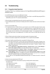
... yes, please disable this device. (If not, skip this button to show the advanced options. Q: What do the beeps emitted during the POST. A: The following Award BIOS beep code descriptions may help you identify possible computer problems. (For reference only.) 1 short: System boots successfully 1 long, 3 short: Keyboard error 2 short: CMOS setting error 1 long, 9 short: BIOS ROM error 1 long, 1 short: Memory or motherboard error Continuous long beeps: Graphics card not inserted properly 1 long, 2 short: Monitor or graphics card error Continuous short beeps: Power error - 119...
... yes, please disable this device. (If not, skip this button to show the advanced options. Q: What do the beeps emitted during the POST. A: The following Award BIOS beep code descriptions may help you identify possible computer problems. (For reference only.) 1 short: System boots successfully 1 long, 3 short: Keyboard error 2 short: CMOS setting error 1 long, 9 short: BIOS ROM error 1 long, 1 short: Memory or motherboard error Continuous long beeps: Graphics card not inserted properly 1 long, 2 short: Monitor or graphics card error Continuous short beeps: Power error - 119...


