
Manual
Page 1
...With GIGABYTE eXtreme Hard Drive (X.H.D)(Note 1), users can quickly configure a RAIDready system for complex and time-consuming configurations. A. You can click the Xpress Install All button to Chapter 5, "Installing the SATA RAID/AHCI Driver and Operating System." ) Step 3: Install the motherboard drivers... and the X.H.D utiltiy After installing the operating system, insert the motherboard driver disk. To automatically set up a RAID 0 array: Click Auto to automatically and quickly...
...With GIGABYTE eXtreme Hard Drive (X.H.D)(Note 1), users can quickly configure a RAIDready system for complex and time-consuming configurations. A. You can click the Xpress Install All button to Chapter 5, "Installing the SATA RAID/AHCI Driver and Operating System." ) Step 3: Install the motherboard drivers... and the X.H.D utiltiy After installing the operating system, insert the motherboard driver disk. To automatically set up a RAID 0 array: Click Auto to automatically and quickly...
Manual
Page 1
GA-P55-UD3P GA-P55-UD3R LGA1156 socket motherboard for Intel® Core™ i7 processor family/ Intel® Core™ i5 processor family User's Manual Rev. 1001 12ME-P55UD3P-1001R
GA-P55-UD3P GA-P55-UD3R LGA1156 socket motherboard for Intel® Core™ i7 processor family/ Intel® Core™ i5 processor family User's Manual Rev. 1001 12ME-P55UD3P-1001R
Manual
Page 3
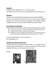
... the Quick Installation Guide included with the product. Example: For example, "REV: 1.0" means the revision of the motherboard is the property of GIGABYTE. The trademarks mentioned in this manual are legally registered to the specifications and features in this manual is protected by ... is 1.0. Changes to their respective owners. For instructions on how to assist in any form or by GIGABYTE without GIGABYTE's prior written permission. Check your motherboard looks like this manual may be made by any means without prior notice. All rights reserved. Copyright ©...
... the Quick Installation Guide included with the product. Example: For example, "REV: 1.0" means the revision of the motherboard is the property of GIGABYTE. The trademarks mentioned in this manual are legally registered to the specifications and features in this manual is protected by ... is 1.0. Changes to their respective owners. For instructions on how to assist in any form or by GIGABYTE without GIGABYTE's prior written permission. Check your motherboard looks like this manual may be made by any means without prior notice. All rights reserved. Copyright ©...
Manual
Page 4
Table of Contents Box Contents...6 Optional Items...6 GA-P55-UD3P/GA-P55-UD3R Motherboard Layout 7 Block Diagram...8 Chapter 1 Hardware Installation 9 1-1 Installation Precautions 9 1-2 Product Specifications 10 1-3 Installing the CPU and CPU Cooler 13 1-3-1 Installing the CPU 13 1-3-2 Installing the CPU ...
Table of Contents Box Contents...6 Optional Items...6 GA-P55-UD3P/GA-P55-UD3R Motherboard Layout 7 Block Diagram...8 Chapter 1 Hardware Installation 9 1-1 Installation Precautions 9 1-2 Product Specifications 10 1-3 Installing the CPU and CPU Cooler 13 1-3-1 Installing the CPU 13 1-3-2 Installing the CPU ...
Manual
Page 6
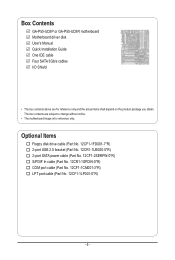
Box Contents GA-P55-UD3P or GA-P55-UD3R motherboard Motherboard driver disk User's Manual Quick Installation Guide One IDE cable Four SATA 3Gb/s cables I/O Shield • The box contents above are subject to change without notice. • The motherboard image is for reference only and the actual items shall depend on the product package you obtain. The box...
Box Contents GA-P55-UD3P or GA-P55-UD3R motherboard Motherboard driver disk User's Manual Quick Installation Guide One IDE cable Four SATA 3Gb/s cables I/O Shield • The box contents above are subject to change without notice. • The motherboard image is for reference only and the actual items shall depend on the product package you obtain. The box...
Manual
Page 7
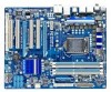
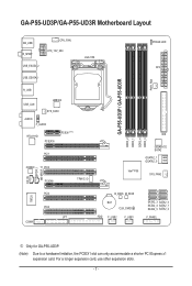
GA-P55-UD3P/GA-P55-UD3R Motherboard Layout KB_USB R_SPDIF CPU_FAN ATX_12V_2X4 USB_ESATA_2 USB_ESATA_1 LGA1156 PHASE LED ATX PWR_FAN GA-P55-UD3P / GA-P55-UD3R R_USB USB_LAN JMB362 SYS_FAN1 AUDIO F_AUDIO RTL8111D PCIEX16 PCIEX1(Note) PCI1 CODEC PCI2 PCIEX4 TPM IC j DDR3_2 DDR3_1 IDE DDR3_4 DDR3_3 GIGABYTE SATA2 GSATA2_1 GSATA2_0 Intel® P55 SYS_FAN2 CD_IN SPDIF_I SPDIF_O IT8720 PCI3 PCI4 LPT COMA B_BIOS M_BIOS...
GA-P55-UD3P/GA-P55-UD3R Motherboard Layout KB_USB R_SPDIF CPU_FAN ATX_12V_2X4 USB_ESATA_2 USB_ESATA_1 LGA1156 PHASE LED ATX PWR_FAN GA-P55-UD3P / GA-P55-UD3R R_USB USB_LAN JMB362 SYS_FAN1 AUDIO F_AUDIO RTL8111D PCIEX16 PCIEX1(Note) PCI1 CODEC PCI2 PCIEX4 TPM IC j DDR3_2 DDR3_1 IDE DDR3_4 DDR3_3 GIGABYTE SATA2 GSATA2_1 GSATA2_0 Intel® P55 SYS_FAN2 CD_IN SPDIF_I SPDIF_O IT8720 PCI3 PCI4 LPT COMA B_BIOS M_BIOS...
Manual
Page 9
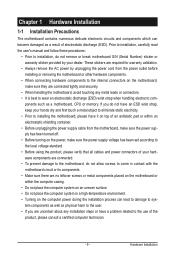
...turned off. • Before turning on the power, make sure they are connected tightly and securely. • When handling the motherboard, avoid touching any installation steps or have it on top of an antistatic pad or within an electrostatic shielding container. • Before... unplugging the power supply cable from the power outlet before installing or removing the motherboard or other hardware components. • When connecting hardware components to the internal connectors on the computer power during the installation process...
...turned off. • Before turning on the power, make sure they are connected tightly and securely. • When handling the motherboard, avoid touching any installation steps or have it on top of an antistatic pad or within an electrostatic shielding container. • Before... unplugging the power supply cable from the power outlet before installing or removing the motherboard or other hardware components. • When connecting hardware components to the internal connectors on the computer power during the installation process...
Manual
Page 12
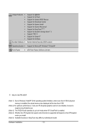
... Internet Security (OEM version) Operating System w Support for Microsoft® Windows® 7/Vista/XP Form Factor w ATX Form Factor; 30.5cm x 24.4cm j Only for GA-P55-UD3P. (Note 1) Due to Windows Vista/XP 32-bit operating system limitation, when more than 4 GB of physical memory is installed, the actual memory size... CPU/system fan speed control function is supported will depend on the CPU/system cooler you install. (Note 5) Available functions in EasyTune may differ by motherboard model. Hardware Installation - 12 -
... Internet Security (OEM version) Operating System w Support for Microsoft® Windows® 7/Vista/XP Form Factor w ATX Form Factor; 30.5cm x 24.4cm j Only for GA-P55-UD3P. (Note 1) Due to Windows Vista/XP 32-bit operating system limitation, when more than 4 GB of physical memory is installed, the actual memory size... CPU/system fan speed control function is supported will depend on the CPU/system cooler you install. (Note 5) Available functions in EasyTune may differ by motherboard model. Hardware Installation - 12 -
Manual
Page 13
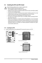
... standard requirements for the latest CPU support list.) • Always turn on the computer if the CPU cooler is not recommended that the motherboard supports the CPU. (Go to GIGABYTE's website for the peripherals. 1-3 Installing the CPU and CPU Cooler Read the following guidelines before installing the CPU to prevent hardware damage... CPU A. Hardware Installation age of the CPU Socket LGA1156 CPU Notch Notch Triangle Pin One Marking on the CPU. Locate the alignment keys on the motherboard CPU socket and the notches on the CPU - 13 -
... standard requirements for the latest CPU support list.) • Always turn on the computer if the CPU cooler is not recommended that the motherboard supports the CPU. (Go to GIGABYTE's website for the peripherals. 1-3 Installing the CPU and CPU Cooler Read the following guidelines before installing the CPU to prevent hardware damage... CPU A. Hardware Installation age of the CPU Socket LGA1156 CPU Notch Notch Triangle Pin One Marking on the CPU. Locate the alignment keys on the motherboard CPU socket and the notches on the CPU - 13 -
Manual
Page 14
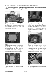
... to turn off the computer and unplug the power cord from the socket with your finger. B. Step 5: Push the CPU socket lever back into the motherboard CPU socket. Step 1: Gently press the CPU socket lever handle down and away from the power outlet to prevent damage to grasp the protective socket...
... to turn off the computer and unplug the power cord from the socket with your finger. B. Step 5: Push the CPU socket lever back into the motherboard CPU socket. Step 1: Gently press the CPU socket lever handle down and away from the power outlet to prevent damage to grasp the protective socket...

Manual
Page 15
...installation, check the back of the CPU cooler to the CPU fan header (CPU_FAN) on the motherboard. 1-3-2 Installing the CPU Cooler Follow the steps below to correctly install the CPU cooler on the motherboard. (The following procedure uses Intel® boxed cooler as the picture above shows, the installation is... the cooler, on the contrary, is inserted as the example cooler.) Step 1: Apply an even and thin layer of thermal grease on the motherboard. Hardware Installation Direction of the Arrow Sign on the Male Push Pin Male Push Pin The Top of Female Push Pin Female Push Pin Step...
...installation, check the back of the CPU cooler to the CPU fan header (CPU_FAN) on the motherboard. 1-3-2 Installing the CPU Cooler Follow the steps below to correctly install the CPU cooler on the motherboard. (The following procedure uses Intel® boxed cooler as the picture above shows, the installation is... the cooler, on the contrary, is inserted as the example cooler.) Step 1: Apply an even and thin layer of thermal grease on the motherboard. Hardware Installation Direction of the Arrow Sign on the Male Push Pin Male Push Pin The Top of Female Push Pin Female Push Pin Step...
Manual
Page 16
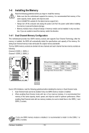
... memory sockets and supports Dual Channel Technology. The four DDR3 memory sockets are unable to install the memory: • Make sure that the motherboard supports the memory. When enabling Dual Channel mode with two memory modules, be installed in Dual Channel mode. 1. Hardware Installation - 16 -...the same capacity, brand, speed, and chips be enabled if only one direction. Dual Channel mode cannot be used . (Go to GIGABYTE's website for optimum performance. If only one DDR3 memory module is installed, the BIOS will double the original memory bandwidth. DS/SS Four...
... memory sockets and supports Dual Channel Technology. The four DDR3 memory sockets are unable to install the memory: • Make sure that the motherboard supports the memory. When enabling Dual Channel mode with two memory modules, be installed in Dual Channel mode. 1. Hardware Installation - 16 -...the same capacity, brand, speed, and chips be enabled if only one direction. Dual Channel mode cannot be used . (Go to GIGABYTE's website for optimum performance. If only one DDR3 memory module is installed, the BIOS will double the original memory bandwidth. DS/SS Four...
Manual
Page 17
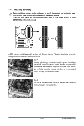
..., make sure to turn off the computer and unplug the power cord from the power outlet to prevent damage to install DDR3 DIMMs on this motherboard. Hardware Installation As indicated in the picture on the top edge of the memory socket. Follow the steps below to correctly install your fingers on...
..., make sure to turn off the computer and unplug the power cord from the power outlet to prevent damage to install DDR3 DIMMs on this motherboard. Hardware Installation As indicated in the picture on the top edge of the memory socket. Follow the steps below to correctly install your fingers on...
Manual
Page 18
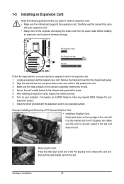
... a screw. 5. Make sure the metal contacts on your operating system. If necessary, go to BIOS Setup to install an expansion card: • Make sure the motherboard supports the expansion card. Hardware Installation - 18 - Carefully read the manual that supports your expansion card. • Always turn off the computer and unplug the...
... a screw. 5. Make sure the metal contacts on your operating system. If necessary, go to BIOS Setup to install an expansion card: • Make sure the motherboard supports the expansion card. Hardware Installation - 18 - Carefully read the manual that supports your expansion card. • Always turn off the computer and unplug the...
Manual
Page 19
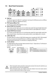
... Out Connector This connector provides digital audio out to a back panel connector, first remove the cable from your device and then remove it from the motherboard. • When removing the cable, pull it side to side to 1 Gbps data rate. PS/2 Keyboard/Mouse Port Use this port for instructions on configuring...
... Out Connector This connector provides digital audio out to a back panel connector, first remove the cable from your device and then remove it from the motherboard. • When removing the cable, pull it side to side to 1 Gbps data rate. PS/2 Keyboard/Mouse Port Use this port for instructions on configuring...
Manual
Page 21
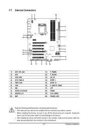
... 13) CD_IN 14) SPDIF_I 15) SPDIF_O 16) F_USB1/F_USB2 17) LPT 18) COMA 19) CLR_CMOS 20) PHASE_LED Read the following guidelines before turning on the motherboard. - 21 -
... 13) CD_IN 14) SPDIF_I 15) SPDIF_O 16) F_USB1/F_USB2 17) LPT 18) COMA 19) CLR_CMOS 20) PHASE_LED Read the following guidelines before turning on the motherboard. - 21 -
Manual
Page 22
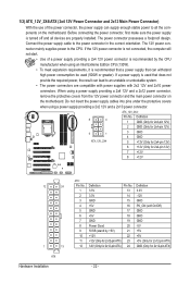
... a power supply providing a 2x4 12V and a 2x12 power connector, remove the protective covers from the 12V power connector and the main power connector on the motherboard. Definition 1 GND (Only for 2x4-pin 12V) 2 GND (Only for 2x4-pin 12V) 3 GND 4 GND 5 +12V (Only for 2x4-pin 12V) 6 +12V (Only for 2x4... a power supply providing a 2x2 12V and a 2x10 power connector. 8 4 5 1 ATX_12V_2X4 ATX_12V_2X4: Pin No. If a power supply is turned off and all the components on the motherboard. Connect the power supply cable to the CPU.
... a power supply providing a 2x4 12V and a 2x12 power connector, remove the protective covers from the 12V power connector and the main power connector on the motherboard. Definition 1 GND (Only for 2x4-pin 12V) 2 GND (Only for 2x4-pin 12V) 3 GND 4 GND 5 +12V (Only for 2x4-pin 12V) 6 +12V (Only for 2x4... a power supply providing a 2x2 12V and a 2x10 power connector. 8 4 5 1 ATX_12V_2X4 ATX_12V_2X4: Pin No. If a power supply is turned off and all the components on the motherboard. Connect the power supply cable to the CPU.
Manual
Page 23
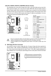
...Before connecting a floppy disk drive, be installed inside the chassis. The pin 1 of the cable is the ground wire). The motherboard supports CPU fan speed control, which requires the use of floppy disk drives supported are not configuration jumper blocks. For optimum heat ... design. Definition 1 CPU_FAN 1 GND 2 +12V / Speed Control 3 Sense 4 Speed Control SYS_FAN2: Pin No. 3/4/5) CPU_FAN/SYS_FAN1/SYS_FAN2/PWR_FAN (Fan Headers) The motherboard has a 4-pin CPU fan header (CPU_FAN), a 4-pin (SYS_FAN2) and two 3-pin (SYS_ FAN1) system fan headers, and a 3-pin power fan header (...
...Before connecting a floppy disk drive, be installed inside the chassis. The pin 1 of the cable is the ground wire). The motherboard supports CPU fan speed control, which requires the use of floppy disk drives supported are not configuration jumper blocks. For optimum heat ... design. Definition 1 CPU_FAN 1 GND 2 +12V / Speed Control 3 Sense 4 Speed Control SYS_FAN2: Pin No. 3/4/5) CPU_FAN/SYS_FAN1/SYS_FAN2/PWR_FAN (Fan Headers) The motherboard has a 4-pin CPU fan header (CPU_FAN), a 4-pin (SYS_FAN2) and two 3-pin (SYS_ FAN1) system fan headers, and a 3-pin power fan header (...
Manual
Page 27
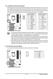
... both of the front and back panel audio connections simultaneously. Hardware Installation Incorrect connection between the module connector and the motherboard header will be present on each wire instead of the motherboard header. Definition 1 CD-L 2 GND 3 GND 1 4 CD-R - 27 - For HD Front Panel Audio: For AC'97 Front Panel Audio: Pin No...
... both of the front and back panel audio connections simultaneously. Hardware Installation Incorrect connection between the module connector and the motherboard header will be present on each wire instead of the motherboard header. Definition 1 CD-L 2 GND 3 GND 1 4 CD-R - 27 - For HD Front Panel Audio: For AC'97 Front Panel Audio: Pin No...
Manual
Page 28
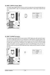
... (S/PDIF Out Header) This header supports digital S/PDIF Out and connects a S/PDIF digital audio cable (provided by expansion cards) for digital audio output from your motherboard to your graphics card if you to use a S/PDIF digital audio cable for digital audio output from the HDMI display at the same time. Definition... have digital audio output from your expansion card. Pin No. For information about connecting the S/PDIF digital audio cable, carefully read the manual for your motherboard to an audio device that supports digital audio out via an optional S/PDIF In cable.
... (S/PDIF Out Header) This header supports digital S/PDIF Out and connects a S/PDIF digital audio cable (provided by expansion cards) for digital audio output from your motherboard to your graphics card if you to use a S/PDIF digital audio cable for digital audio output from the HDMI display at the same time. Definition... have digital audio output from your expansion card. Pin No. For information about connecting the S/PDIF digital audio cable, carefully read the manual for your motherboard to an audio device that supports digital audio out via an optional S/PDIF In cable.


