Manual
Page 1
GA-P55-UD3L-TPM/ GA-P55-UD3L/ GA-P55-US3L LGA1156 socket motherboard for Intel® Core™ i7 processor family/ Intel® Core™ i5 processor family User's Manual Rev. 1002 12ME-P55UD3L-1002R
GA-P55-UD3L-TPM/ GA-P55-UD3L/ GA-P55-US3L LGA1156 socket motherboard for Intel® Core™ i7 processor family/ Intel® Core™ i5 processor family User's Manual Rev. 1002 12ME-P55UD3L-1002R

Manual
Page 3
Motherboard GA-P55-UD3L-TPM Oct. 5, 2009 Motherboard GA-P55-UD3L-TPM Oct. 5, 2009
Motherboard GA-P55-UD3L-TPM Oct. 5, 2009 Motherboard GA-P55-UD3L-TPM Oct. 5, 2009
Manual
Page 5
Table of Contents Box Contents...7 Optional Items...7 GA-P55-UD3L-TPM/GA-P55-UD3L/GA-P55-US3L Motherboard Layout 8 Block Diagram...9 Chapter 1 Hardware Installation 11 1-1 Installation Precautions 11 1-2 Product Specifications 12 1-3 Installing the CPU and CPU Cooler 15 1-3-1 Installing the CPU ...
Table of Contents Box Contents...7 Optional Items...7 GA-P55-UD3L-TPM/GA-P55-UD3L/GA-P55-US3L Motherboard Layout 8 Block Diagram...9 Chapter 1 Hardware Installation 11 1-1 Installation Precautions 11 1-2 Product Specifications 12 1-3 Installing the CPU and CPU Cooler 15 1-3-1 Installing the CPU ...
Manual
Page 6
...Dynamic Energy Saver™ 2 75 4-5 Q-Share...77 4-6 Smart 6™ ...78 4-7 Smart TPM j 81 4-8 Auto Green...82 4-9 eXtreme Hard Drive (X.H.D 83 Chapter 5 Appendix...85 5-1 Configuring SATA Hard Drive(s 85 5-1-1 Configuring Intel P55 SATA Controllers 85 5-1-2 Configuring GIGABYTE SATA2 SATA Controller 93 5-1-3 Making a SATA RAID/AHCI Driver Diskette 99 5-1-4 Installing the SATA... 116 5-2-4 Using the Sound Recorder 118 5-3 Troubleshooting 119 5-3-1 Frequently Asked Questions 119 5-3-2 Troubleshooting Procedure 120 5-4 Regulatory Statements 122 j Only for GA-P55-UD3L-TPM. - 6 -
...Dynamic Energy Saver™ 2 75 4-5 Q-Share...77 4-6 Smart 6™ ...78 4-7 Smart TPM j 81 4-8 Auto Green...82 4-9 eXtreme Hard Drive (X.H.D 83 Chapter 5 Appendix...85 5-1 Configuring SATA Hard Drive(s 85 5-1-1 Configuring Intel P55 SATA Controllers 85 5-1-2 Configuring GIGABYTE SATA2 SATA Controller 93 5-1-3 Making a SATA RAID/AHCI Driver Diskette 99 5-1-4 Installing the SATA... 116 5-2-4 Using the Sound Recorder 118 5-3 Troubleshooting 119 5-3-1 Frequently Asked Questions 119 5-3-2 Troubleshooting Procedure 120 5-4 Regulatory Statements 122 j Only for GA-P55-UD3L-TPM. - 6 -
Manual
Page 7
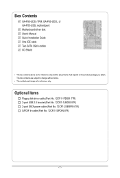
...-5*R) 2-port SATA power cable (Part No. 12CF1-2SERPW-0*R) S/PDIF In cable (Part No. 12CR1-1SPDIN-0*R) - 7 - The box contents are for reference only. Box Contents GA-P55-UD3L-TPM, GA-P55-UD3L, or GA-P55-US3L motherboard Motherboard driver disk User's Manual Quick Installation Guide One IDE cable Two SATA 3Gb/s cables I/O Shield • The box contents above are subject...
...-5*R) 2-port SATA power cable (Part No. 12CF1-2SERPW-0*R) S/PDIF In cable (Part No. 12CR1-1SPDIN-0*R) - 7 - The box contents are for reference only. Box Contents GA-P55-UD3L-TPM, GA-P55-UD3L, or GA-P55-US3L motherboard Motherboard driver disk User's Manual Quick Installation Guide One IDE cable Two SATA 3Gb/s cables I/O Shield • The box contents above are subject...
Manual
Page 8
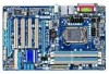
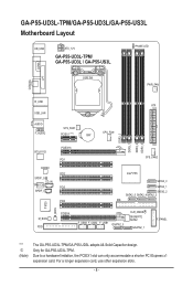
... SATA2_2 SATA2_5 SATA2_4SATA2_3 IDE IT8720 B_BIOS M_BIOS FDD PCIEX4 F_USB3 F_USB2 F_USB1 GSATA2_0 CLR_CMOS GIGABYTE SATA2 GSATA2_1 F_PANEL "*" j (Note) The GA-P55-UD3L-TPM/GA-P55-UD3L adopts All-Solid Capacitor design. Due to a hardware limitation, the PCIEX1 slot can only accommodate a shorter PCI Express x1 expansion card. Only for GA-P55-UD3L-TPM. For a longer expansion card, use other expansion slots. - 8 -
... SATA2_2 SATA2_5 SATA2_4SATA2_3 IDE IT8720 B_BIOS M_BIOS FDD PCIEX4 F_USB3 F_USB2 F_USB1 GSATA2_0 CLR_CMOS GIGABYTE SATA2 GSATA2_1 F_PANEL "*" j (Note) The GA-P55-UD3L-TPM/GA-P55-UD3L adopts All-Solid Capacitor design. Due to a hardware limitation, the PCIEX1 slot can only accommodate a shorter PCI Express x1 expansion card. Only for GA-P55-UD3L-TPM. For a longer expansion card, use other expansion slots. - 8 -
Manual
Page 9
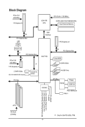
... Express Bus x1 PCIe CLK (100 MHz) x1 1 PCI Express x1 2 SATA 3Gb/s ATA-133/100/66/33 IDE Channel GIGABYTE SATA2 PCI Bus DMI Interface 1 PCI Express x4 Intel® P55 x4 PCI Express Bus Dual BIOS 6 SATA 3Gb/s 14 USB Ports CODEC LPC Bus IT8720 Floppy COM Port PS/2 KB.../Mouse TPM j MIC (Center/Subwoofer Speaker Out) Line-Out (Front Speaker Out) Line-In (Rear Speaker Out) S/PDIF In S/PDIF Out 4 PCI PCI CLK (33 MHz) j Only for GA-P55-UD3L-TPM. - 9 -
... Express Bus x1 PCIe CLK (100 MHz) x1 1 PCI Express x1 2 SATA 3Gb/s ATA-133/100/66/33 IDE Channel GIGABYTE SATA2 PCI Bus DMI Interface 1 PCI Express x4 Intel® P55 x4 PCI Express Bus Dual BIOS 6 SATA 3Gb/s 14 USB Ports CODEC LPC Bus IT8720 Floppy COM Port PS/2 KB.../Mouse TPM j MIC (Center/Subwoofer Speaker Out) Line-Out (Front Speaker Out) Line-In (Rear Speaker Out) S/PDIF In S/PDIF Out 4 PCI PCI CLK (33 MHz) j Only for GA-P55-UD3L-TPM. - 9 -
Manual
Page 12
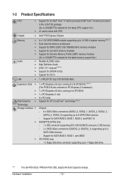
...x4 (PCIEX4) 1 x PCI Express x1 slot 4 x PCI slots Multi-Graphics Support for SATA RAID 0, RAID 1, RAID 5, and RAID 10 GIGABYTE SATA2 chip: - 1 x IDE connector supporting ATA-133/100/66/33 and up to 2 IDE devices - 2 x SATA 3Gb/s connectors (GSATA2_0, GSATA2_1) supporting up to 2 SATA 3Gb... - 12 - Support for SATA RAID 0, RAID 1, and JBOD iTE IT8720 chip: - 1 x floppy disk drive connector supporting up to 1 floppy disk drive "*" The GA-P55-UD3L-TPM/GA-P55-UD3L adopts All-Solid Capacitor design.
...x4 (PCIEX4) 1 x PCI Express x1 slot 4 x PCI slots Multi-Graphics Support for SATA RAID 0, RAID 1, RAID 5, and RAID 10 GIGABYTE SATA2 chip: - 1 x IDE connector supporting ATA-133/100/66/33 and up to 2 IDE devices - 2 x SATA 3Gb/s connectors (GSATA2_0, GSATA2_1) supporting up to 2 SATA 3Gb... - 12 - Support for SATA RAID 0, RAID 1, and JBOD iTE IT8720 chip: - 1 x floppy disk drive connector supporting up to 1 floppy disk drive "*" The GA-P55-UD3L-TPM/GA-P55-UD3L adopts All-Solid Capacitor design.
Manual
Page 14
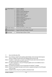
... Internet Security (OEM version) Operating System w Support for Microsoft® Windows® 7/Vista/XP Form Factor w ATX Form Factor; 30.5cm x 19.0cm j Only for GA-P55-UD3L-TPM. (Note 1) Due to Windows Vista/XP 32-bit operating system limitation, when more than 4 GB of physical memory is installed, the actual memory size displayed...
... Internet Security (OEM version) Operating System w Support for Microsoft® Windows® 7/Vista/XP Form Factor w ATX Form Factor; 30.5cm x 19.0cm j Only for GA-P55-UD3L-TPM. (Note 1) Due to Windows Vista/XP 32-bit operating system limitation, when more than 4 GB of physical memory is installed, the actual memory size displayed...
Manual
Page 35
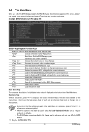
...previous BIOS settings for the current submenus Load the Fail-Safe BIOS default settings for the current submenus Load the Optimized BIOS default settings for GA-P55-UD3L-TPM. - 35 - 2-2 The Main Menu Once you want in the Main Menu or a submenu, press + to access more advanced options... on the screen. Use arrow keys to move among the items and press to accept or enter a sub-menu. (Sample BIOS Version: GA-P55-UD3L D11) CMOS Setup Utility-Copyright (C) 1984-2009 Award Software MB Intelligent Tweaker(M.I.T.) Standard CMOS Features Advanced BIOS Features...
...previous BIOS settings for the current submenus Load the Fail-Safe BIOS default settings for the current submenus Load the Optimized BIOS default settings for GA-P55-UD3L-TPM. - 35 - 2-2 The Main Menu Once you want in the Main Menu or a submenu, press + to access more advanced options... on the screen. Use arrow keys to move among the items and press to accept or enter a sub-menu. (Sample BIOS Version: GA-P55-UD3L D11) CMOS Setup Utility-Copyright (C) 1984-2009 Award Software MB Intelligent Tweaker(M.I.T.) Standard CMOS Features Advanced BIOS Features...
Manual
Page 36
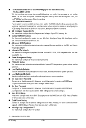
... defaults are factory settings for the most stable, minimal-performance system operations. Load Optimized Defaults Optimized defaults are factory settings for GA-P55-UD3L-TPM. You can create up to configure the TPM function. First select the profile you wish to load, then press to complete. MB Intelligent Tweaker(M.I.T.) Use this menu to...
... defaults are factory settings for the most stable, minimal-performance system operations. Load Optimized Defaults Optimized defaults are factory settings for GA-P55-UD3L-TPM. You can create up to configure the TPM function. First select the profile you wish to load, then press to complete. MB Intelligent Tweaker(M.I.T.) Use this menu to...

Manual
Page 58
In case system instability occurs, you may try to load Fail-Safe defaults, which are the safest and most stable BIOS settings for GA-P55-UD3L-TPM. The BIOS defaults settings help the system to operate in optimum state. Always load the Optimized defaults after updating the BIOS or after clearing the ...
In case system instability occurs, you may try to load Fail-Safe defaults, which are the safest and most stable BIOS settings for GA-P55-UD3L-TPM. The BIOS defaults settings help the system to operate in optimum state. Always load the Optimized defaults after updating the BIOS or after clearing the ...
Manual
Page 59
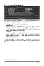
... if you wish to BIOS settings. In BIOS Setup, you must enter the supervisor password for entering BIOS Setup and making BIOS changes. j Only for GA-P55-UD3L-TPM. - 59 - 2-11 Set Supervisor/User Password CMOS Setup Utility-Copyright (C) 1984-2009 Award Software MB Intelligent Tweaker(M.I.T.) Standard CMOS Features Advanced BIOS...
... if you wish to BIOS settings. In BIOS Setup, you must enter the supervisor password for entering BIOS Setup and making BIOS changes. j Only for GA-P55-UD3L-TPM. - 59 - 2-11 Set Supervisor/User Password CMOS Setup Utility-Copyright (C) 1984-2009 Award Software MB Intelligent Tweaker(M.I.T.) Standard CMOS Features Advanced BIOS...

Manual
Page 60
... all Data F11: Save CMOS to BIOS F12: Load CMOS from BIOS Press on this item and press the key. BIOS Setup - 60 - j Only for GA-P55-UD3L-TPM. This exits the BIOS Setup without saving the changes made in BIOS Setup to the CMOS.
... all Data F11: Save CMOS to BIOS F12: Load CMOS from BIOS Press on this item and press the key. BIOS Setup - 60 - j Only for GA-P55-UD3L-TPM. This exits the BIOS Setup without saving the changes made in BIOS Setup to the CMOS.
Manual
Page 61
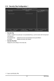
Enabled/Activate Enables the security chip and initializes the Security Platform. j Only for GA-P55-UD3L-TPM. - 61 - Disabled Disables the security chip. (Default) Security Chip State Displays the current settings in the security chip. BIOS Setup 2-14 Security Chip Configuration j CMOS ...
Enabled/Activate Enables the security chip and initializes the Security Platform. j Only for GA-P55-UD3L-TPM. - 61 - Disabled Disables the security chip. (Default) Security Chip State Displays the current settings in the security chip. BIOS Setup 2-14 Security Chip Configuration j CMOS ...
Manual
Page 72
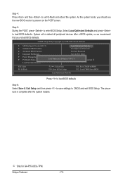
... and exit BIOS Setup. The procedure is present on the POST screen. System will re-detect all peripheral devices after the system restarts. j Only for GA-P55-UD3L-TPM. Unique Features - 72 - CMOS Setup Utility-Copyright (C) 1984-2009 Award Software MB Intelligent Tweaker(M.I.T.) Load Optimized Defaults Standard CMOS Features Set Supervisor Password...
... and exit BIOS Setup. The procedure is present on the POST screen. System will re-detect all peripheral devices after the system restarts. j Only for GA-P55-UD3L-TPM. Unique Features - 72 - CMOS Setup Utility-Copyright (C) 1984-2009 Award Software MB Intelligent Tweaker(M.I.T.) Load Optimized Defaults Standard CMOS Features Set Supervisor Password...
Manual
Page 81
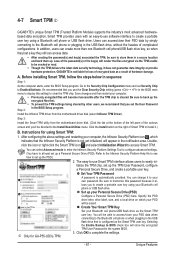
... that is cleared. Instructions for GA-P55-UD3L-TPM. 3. You can access data. • After creating the password(s) and key(s) associated the TPM, be cracked or read. • Though the TPM delivers the latest data security technology, it al- Selecting the Enable Backup to clear the TPM chip. Unique Features 4-7 Smart TPM j GIGABYTE's unique Smart TPM (Trusted Platform Module) supports...
... that is cleared. Instructions for GA-P55-UD3L-TPM. 3. You can access data. • After creating the password(s) and key(s) associated the TPM, be cracked or read. • Though the TPM delivers the latest data security technology, it al- Selecting the Enable Backup to clear the TPM chip. Unique Features 4-7 Smart TPM j GIGABYTE's unique Smart TPM (Trusted Platform Module) supports...

