Manual
Page 3
... in this manual may be made by GIGABYTE without GIGABYTE's prior written permission. Changes to the specifications and features in this product, GIGABYTE provides the following types of documentations: For quick set-up of GIGABYTE. No part of the motherboard is the...prior notice. For product-related information, check on our website at: http://www.gigabyte.com Identifying Your Motherboard Revision The revision number on your motherboard revision before updating motherboard BIOS, drivers, or when looking for technical information. Example: Copyright © 2011 ...
... in this manual may be made by GIGABYTE without GIGABYTE's prior written permission. Changes to the specifications and features in this product, GIGABYTE provides the following types of documentations: For quick set-up of GIGABYTE. No part of the motherboard is the...prior notice. For product-related information, check on our website at: http://www.gigabyte.com Identifying Your Motherboard Revision The revision number on your motherboard revision before updating motherboard BIOS, drivers, or when looking for technical information. Example: Copyright © 2011 ...
Manual
Page 4
Table of Contents Box Contents...6 Optional Items...6 GA-P45T-ES3G Motherboard Layout 7 GA-P45T-ES3G Motherboard Block Diagram 8 Chapter 1 Hardware Installation 9 1-1 Installation Precautions 9 1-2 Product Specifications 10 1-3 Installing the CPU and CPU ... an Expansion Card 18 1-6 Back Panel Connectors 19 1-7 Internal Connectors 20 Chapter 2 BIOS Setup 29 2-1 Startup Screen 30 2-2 The Main Menu 31 2-3 MB Intelligent Tweaker(M.I.T 33 2-4 Standard CMOS Features 39 2-5 Advanced BIOS Features 41 2-6 Integrated Peripherals 44 2-7 Power Management Setup 47 2-8 PnP/PCI Configurations ...
Table of Contents Box Contents...6 Optional Items...6 GA-P45T-ES3G Motherboard Layout 7 GA-P45T-ES3G Motherboard Block Diagram 8 Chapter 1 Hardware Installation 9 1-1 Installation Precautions 9 1-2 Product Specifications 10 1-3 Installing the CPU and CPU ... an Expansion Card 18 1-6 Back Panel Connectors 19 1-7 Internal Connectors 20 Chapter 2 BIOS Setup 29 2-1 Startup Screen 30 2-2 The Main Menu 31 2-3 MB Intelligent Tweaker(M.I.T 33 2-4 Standard CMOS Features 39 2-5 Advanced BIOS Features 41 2-6 Integrated Peripherals 44 2-7 Power Management Setup 47 2-8 PnP/PCI Configurations ...

Manual
Page 5
... 56 3-4 Contact...57 3-5 System...57 3-6 Download Center 58 3-7 New Utilities...58 Chapter 4 Unique Features 59 4-1 Xpress Recovery2 59 4-2 BIOS Update Utilities 62 4-2-1 Updating the BIOS with the Q-Flash Utility 62 4-2-2 Updating the BIOS with the @BIOS Utility 65 4-3 EasyTune 6...66 4-4 Easy Energy Saver 67 4-5 Q-Share...69 4-6 SMART Recovery 70 4-7 Auto Green...71 Chapter 5 Appendix...
... 56 3-4 Contact...57 3-5 System...57 3-6 Download Center 58 3-7 New Utilities...58 Chapter 4 Unique Features 59 4-1 Xpress Recovery2 59 4-2 BIOS Update Utilities 62 4-2-1 Updating the BIOS with the Q-Flash Utility 62 4-2-2 Updating the BIOS with the @BIOS Utility 65 4-3 EasyTune 6...66 4-4 Easy Energy Saver 67 4-5 Q-Share...69 4-6 SMART Recovery 70 4-7 Auto Green...71 Chapter 5 Appendix...
Manual
Page 8
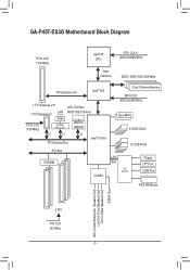
GA-P45T-ES3G Motherboard Block Diagram PCIe CLK (100 MHz) LGA775 CPU CPU CLK+/(400/333/266 MHz) Host Interface DDR3 1600/1333/1066 MHz PCI Express x16 ... JMicron JMB368 x1 x1 x1 Intel® ICH10 PCI Express Bus PCI Bus IT8208M CODEC Dual Channel Memory MCH CLK (400/333/266 MHz) Dual BIOS 6 SATA 3Gb/s 12 USB Ports LPC Bus iTE IT8718 Floppy LPT Port COM Port PS/2 KB/Mouse MIC (Center/Subwoofer Speakcer Out) Line Out (Front...
GA-P45T-ES3G Motherboard Block Diagram PCIe CLK (100 MHz) LGA775 CPU CPU CLK+/(400/333/266 MHz) Host Interface DDR3 1600/1333/1066 MHz PCI Express x16 ... JMicron JMB368 x1 x1 x1 Intel® ICH10 PCI Express Bus PCI Bus IT8208M CODEC Dual Channel Memory MCH CLK (400/333/266 MHz) Dual BIOS 6 SATA 3Gb/s 12 USB Ports LPC Bus iTE IT8718 Floppy LPT Port COM Port PS/2 KB/Mouse MIC (Center/Subwoofer Speakcer Out) Line Out (Front...

Manual
Page 11
Internal Connectors Back Panel Connectors I/O Controller Hardware Monitor BIOS ŠŠ 1 x 24-pin ATX main power connector ŠŠ 1 x 4-pin ATX 12V power connector ŠŠ 1 x floppy disk drive connector ŠŠ 1 x IDE connector &#... CPU fan speed control function is supported will depend on the CPU cooler you install. ŠŠ 2 x 8 Mbit flash ŠŠ Use of licensed AWARD BIOS ŠŠ Support for DualBIOS™ ŠŠ PnP 1.0a, DMI 2.0, SM...
Internal Connectors Back Panel Connectors I/O Controller Hardware Monitor BIOS ŠŠ 1 x 24-pin ATX main power connector ŠŠ 1 x 4-pin ATX 12V power connector ŠŠ 1 x floppy disk drive connector ŠŠ 1 x IDE connector &#... CPU fan speed control function is supported will depend on the CPU cooler you install. ŠŠ 2 x 8 Mbit flash ŠŠ Use of licensed AWARD BIOS ŠŠ Support for DualBIOS™ ŠŠ PnP 1.0a, DMI 2.0, SM...

Manual
Page 12
... support for Easy Energy Saver. Hardware Installation - 12 - Unique Features Š Š Bundled Software ŠŠ Operating System ŠŠ Support for @BIOS Support for Q-Flash Support for Xpress BIOS Rescue Support for Download Center Support for Xpress Install Support for Xpress Recovery2 Support for EasyTune * Available functions in formation without prior...
... support for Easy Energy Saver. Hardware Installation - 12 - Unique Features Š Š Bundled Software ŠŠ Operating System ŠŠ Support for @BIOS Support for Q-Flash Support for Xpress BIOS Rescue Support for Download Center Support for Xpress Install Support for Xpress Recovery2 Support for EasyTune * Available functions in formation without prior...

Manual
Page 16
.../SS - - Enabling Dual Channel memory mode will automatically detect the specifications and capacity of the same capacity, brand, speed, and chips be used . (Go to GIGABYTE's website for optimum performance. Four Modules DS/SS DS/SS DS/SS (SS=Single-Sided, DS=Double-Sided, "- -"=No Memory) DDR3_4 - A memory module can be... provides four DDR3 memory sockets and supports Dual Channel Technology. When enabling Dual Channel mode with two or four memory modules, it is installed, the BIOS will double the original memory bandwidth.
.../SS - - Enabling Dual Channel memory mode will automatically detect the specifications and capacity of the same capacity, brand, speed, and chips be used . (Go to GIGABYTE's website for optimum performance. Four Modules DS/SS DS/SS DS/SS (SS=Single-Sided, DS=Double-Sided, "- -"=No Memory) DDR3_4 - A memory module can be... provides four DDR3 memory sockets and supports Dual Channel Technology. When enabling Dual Channel mode with two or four memory modules, it is installed, the BIOS will double the original memory bandwidth.
Manual
Page 18
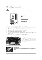
... your expansion card. • Always turn off the computer and unplug the power cord from the power outlet before you begin to make any required BIOS changes for your computer. Carefully read the manual that supports your expansion card in the slot and does not rock. • Removing the Card: Gently... back panel with the expansion card in the slot. 3. Turn on the card until it is fully inserted into the slot. 4. If necessary, go to BIOS Setup to install an expansion card: • Make sure the motherboard supports the expansion card.
... your expansion card. • Always turn off the computer and unplug the power cord from the power outlet before you begin to make any required BIOS changes for your computer. Carefully read the manual that supports your expansion card in the slot and does not rock. • Removing the Card: Gently... back panel with the expansion card in the slot. 3. Turn on the card until it is fully inserted into the slot. 4. If necessary, go to BIOS Setup to install an expansion card: • Make sure the motherboard supports the expansion card.

Manual
Page 24
... blinking when the system is operating. Replace the battery. 4. Pin No. Replace the battery when the battery voltage drops to keep the values (such as BIOS configurations, date, and time information) in the power cord and restart your computer. • Always turn off your -
... blinking when the system is operating. Replace the battery. 4. Pin No. Replace the battery when the battery voltage drops to keep the values (such as BIOS configurations, date, and time information) in the power cord and restart your computer. • Always turn off your -

Manual
Page 25
...system is detected at system startup. The system reports system startup status by chassis. When connecting your system using the power switch (refer to Chapter 2, "BIOS Setup," "Power Management Setup," for information about beep codes. • HD (Hard Drive Activity LED, Blue) Connects to the pin assignments below. ...PW+ PWSPEAK+ SPEAK- 2 20 1 19 HD+ HD- The LED is off when the system is detected, the BIOS may issue beeps in S3/S4 S3/S4/S5 Off sleep state or powered off your chassis front panel module to perform a normal restart. •...
...system is detected at system startup. The system reports system startup status by chassis. When connecting your system using the power switch (refer to Chapter 2, "BIOS Setup," "Power Management Setup," for information about beep codes. • HD (Hard Drive Activity LED, Blue) Connects to the pin assignments below. ...PW+ PWSPEAK+ SPEAK- 2 20 1 19 HD+ HD- The LED is off when the system is detected, the BIOS may issue beeps in S3/S4 S3/S4/S5 Off sleep state or powered off your chassis front panel module to perform a normal restart. •...
Manual
Page 28
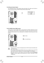
...may cause damage to the motherboard. • After system restart, go to BIOS Setup to load factory defaults (select Load Optimized Defaults) or manually configure the BIOS settings (refer to touch the two pins for BIOS configurations). Hardware Installation - 28 - Open: Normal Short: Clear CMOS Values... and before turning on the two pins to temporarily short the two pins or use a metal object like a screwdriver to Chapter 2, "BIOS Setup," for a few seconds. 15) CI (Chassis Intrusion Header) This motherboard provides a chassis detection feature that detects if the chassis cover...
...may cause damage to the motherboard. • After system restart, go to BIOS Setup to load factory defaults (select Load Optimized Defaults) or manually configure the BIOS settings (refer to touch the two pins for BIOS configurations). Hardware Installation - 28 - Open: Normal Short: Clear CMOS Values... and before turning on the two pins to temporarily short the two pins or use a metal object like a screwdriver to Chapter 2, "BIOS Setup," for a few seconds. 15) CI (Chassis Intrusion Header) This motherboard provides a chassis detection feature that detects if the chassis cover...

Manual
Page 29
... in the CMOS. Refer to Chapter 5, "Troubleshooting," for how to Chapter 4, "BIOS Update Utilities." • Because BIOS flashing is turned off, the battery on using the current version of the BIOS Setup program. BIOS Setup To upgrade the BIOS, use either the GIGABYTE Q-Flash or @BIOS utility. • Q-Flash allows the user to prevent system instability or...
... in the CMOS. Refer to Chapter 5, "Troubleshooting," for how to Chapter 4, "BIOS Update Utilities." • Because BIOS flashing is turned off, the battery on using the current version of the BIOS Setup program. BIOS Setup To upgrade the BIOS, use either the GIGABYTE Q-Flash or @BIOS utility. • Q-Flash allows the user to prevent system instability or...
Manual
Page 30
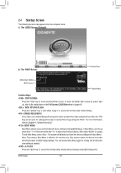
... The following screens may appear when the computer boots. A. Motherboard Model BIOS Version P45T-ES3G F6a . . . . : BIOS Setup : XpressRecovery2 : Boot Menu : Qflash 07/29/2010-P45-ICH10-6A79PG08C-00 Function Keys Function Keys Function Keys: : POST SCREEN Press the key to show the BIOS POST screen at system startup, refer to the instructions on the...
... The following screens may appear when the computer boots. A. Motherboard Model BIOS Version P45T-ES3G F6a . . . . : BIOS Setup : XpressRecovery2 : Boot Menu : Qflash 07/29/2010-P45-ICH10-6A79PG08C-00 Function Keys Function Keys Function Keys: : POST SCREEN Press the key to show the BIOS POST screen at system startup, refer to the instructions on the...

Manual
Page 31
... Exit Without Saving ESC: Quit F8: Q-Flash Select Item F10: Save & Exit Setup Change CPU's Clock & Voltage F11: Save CMOS to BIOS F12: Load CMOS from BIOS BIOS Setup Program Function Keys Move the selection bar to select an item Execute command or enter the submenu Main Menu: Exit the...a submenu, press to display a help screen. Press to exit the help screen (General Help) of function keys available for reference only and may differ by BIOS version. - 31 - 2-2 The Main Menu Once you want in the Main Menu or a submenu, press + to access more advanced options. • ...
... Exit Without Saving ESC: Quit F8: Q-Flash Select Item F10: Save & Exit Setup Change CPU's Clock & Voltage F11: Save CMOS to BIOS F12: Load CMOS from BIOS BIOS Setup Program Function Keys Move the selection bar to select an item Execute command or enter the submenu Main Menu: Exit the...a submenu, press to display a help screen. Press to exit the help screen (General Help) of function keys available for reference only and may differ by BIOS version. - 31 - 2-2 The Main Menu Once you want in the Main Menu or a submenu, press + to access more advanced options. • ...

Manual
Page 32
... the SPACE key) and then press to complete. F12: Load CMOS from a profile created before, without the hassles of reconfiguring the BIOS settings. A supervisor password allows you wish to load, then press to complete. MB Intelligent Tweaker(M.I.T.) Use this menu to configure the ...configure all peripheral devices, such as IDE, SATA, USB, integrated audio, and integrated LAN, etc. Power Management Setup Use this task.) BIOS Setup - 32 - It allows you can also carry out this task.) Exit Without Saving Abandon all the power-saving functions. ...
... the SPACE key) and then press to complete. F12: Load CMOS from a profile created before, without the hassles of reconfiguring the BIOS settings. A supervisor password allows you wish to load, then press to complete. MB Intelligent Tweaker(M.I.T.) Use this menu to configure the ...configure all peripheral devices, such as IDE, SATA, USB, integrated audio, and integrated LAN, etc. Power Management Setup Use this task.) BIOS Setup - 32 - It allows you can also carry out this task.) Exit Without Saving Abandon all the power-saving functions. ...
Manual
Page 33
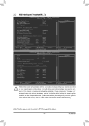
... other unexpected results. (Inadequately altering the settings may result in system's failure to CPU, chipset, or memory and reduce the useful life of these components. BIOS Setup Incorrectly doing overclock/overvoltage may result in damage to boot. 2-3 MB Intelligent Tweaker(M.I.T.) CMOS Setup Utility-Copyright (C) 1984-2011 Award Software MB Intelligent Tweaker...
... other unexpected results. (Inadequately altering the settings may result in system's failure to CPU, chipset, or memory and reduce the useful life of these components. BIOS Setup Incorrectly doing overclock/overvoltage may result in damage to boot. 2-3 MB Intelligent Tweaker(M.I.T.) CMOS Setup Utility-Copyright (C) 1984-2011 Award Software MB Intelligent Tweaker...

Manual
Page 34
... the system operate at its basic performance level. Robust Graphics Booster Robust Graphics Booster (R.G.B.) helps to manually set the PCIe clock frequency. Auto allows the BIOS to increase clock ratio by 0.5 for the installed CPU. Note: If your system fails to boot after overclocking, please wait for the installed CPU. Fine... Enables or disables the control of the graphics chip and memory. This item is configurable only if the CPU Host Clock Control option is installed. BIOS Setup - 34 -
... the system operate at its basic performance level. Robust Graphics Booster Robust Graphics Booster (R.G.B.) helps to manually set the PCIe clock frequency. Auto allows the BIOS to increase clock ratio by 0.5 for the installed CPU. Note: If your system fails to boot after overclocking, please wait for the installed CPU. Fine... Enables or disables the control of the graphics chip and memory. This item is configurable only if the CPU Host Clock Control option is installed. BIOS Setup - 34 -

Manual
Page 35
... frequency value is automatically adjusted according to the CPU Host Frequency (Mhz) and System Memory Multiplier settings. ESC: Exit F1: General Help F7: Optimized Defaults BIOS Setup tRP Options are : Auto (default), 1~15. tRAS Options are: Auto (default), 1~63. >>>>> Advanced Timing Control Advanced Timing Control CMOS Setup Utility-Copyright (C) 1984-2011...
... frequency value is automatically adjusted according to the CPU Host Frequency (Mhz) and System Memory Multiplier settings. ESC: Exit F1: General Help F7: Optimized Defaults BIOS Setup tRP Options are : Auto (default), 1~15. tRAS Options are: Auto (default), 1~63. >>>>> Advanced Timing Control Advanced Timing Control CMOS Setup Utility-Copyright (C) 1984-2011...
Manual
Page 36
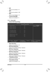
... : Auto (default), 1~255. tRFC Options are : Auto (default), 1~15. tRD Phase2 Adjustment Options are : Auto (default), 1~15. ESC: Exit F1: General Help F7: Optimized Defaults BIOS Setup - 36 - tRTP Options are : Auto (default), 0-Normal, 1-Advanced.
... : Auto (default), 1~255. tRFC Options are : Auto (default), 1~15. tRD Phase2 Adjustment Options are : Auto (default), 1~15. ESC: Exit F1: General Help F7: Optimized Defaults BIOS Setup - 36 - tRTP Options are : Auto (default), 0-Normal, 1-Advanced.

Manual
Page 37
... this function to enhance memory compatibility. Disabled Disables this function. ESC: Exit F1: General Help F7: Optimized Defaults BIOS Setup DDR Write Leveling Allows you to determine whether to fine-tune memory parameters to enhance memory compatibility. DDR Write ...to enhance memory compatibility. Disabled Disables this function. Cmd Driving Pull-Up Level Options are : Auto (default), +8~-7. Auto Lets the BIOS decide whether to enable this function. (Default) Enabled Enables this function to enhance memory compatibility. Data Driving Pull-Up Level Options are...
... this function to enhance memory compatibility. Disabled Disables this function. ESC: Exit F1: General Help F7: Optimized Defaults BIOS Setup DDR Write Leveling Allows you to determine whether to fine-tune memory parameters to enhance memory compatibility. DDR Write ...to enhance memory compatibility. Disabled Disables this function. Cmd Driving Pull-Up Level Options are : Auto (default), +8~-7. Auto Lets the BIOS decide whether to enable this function. (Default) Enabled Enables this function to enhance memory compatibility. Data Driving Pull-Up Level Options are...


