Manual
Page 4
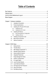
Table of Contents Box Contents...6 Optional Items...6 GA-P41-ES3G Motherboard Layout 7 Block Diagram...8 Chapter 1 Hardware Installation 9 1-1 Installation Precautions 9 1-2 Product Specifications 10 1-3 Installing the CPU and CPU Cooler 13 1-3-1 Installing the CPU 13 1-3-2 Installing the CPU Cooler 15 1-4 Installing the Memory 16 1-4-1 Dual Channel Memory Configuration 16 1-4-2 Installing a Memory 17 1-5 Installing an Expansion Card 18 1-6 Back Panel Connectors...
Table of Contents Box Contents...6 Optional Items...6 GA-P41-ES3G Motherboard Layout 7 Block Diagram...8 Chapter 1 Hardware Installation 9 1-1 Installation Precautions 9 1-2 Product Specifications 10 1-3 Installing the CPU and CPU Cooler 13 1-3-1 Installing the CPU 13 1-3-2 Installing the CPU Cooler 15 1-4 Installing the Memory 16 1-4-1 Dual Channel Memory Configuration 16 1-4-2 Installing a Memory 17 1-5 Installing an Expansion Card 18 1-6 Back Panel Connectors...
Manual
Page 8
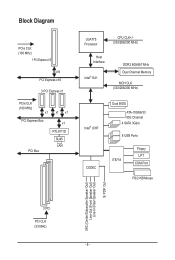
Block Diagram PCIe CLK (100 MHz) 1 PCI Express x16 x16 PCI Express x16 3 PCI Express x1 PCIe CLK (100 MHz) x1 x1 x1 PCI Express Bus x1 RTL8111D RJ45 LAN PCI Bus LGA775 Processor CPU CLK+/(333/266/200 MHz) Host Interface Intel® G41 DDR2 800/667 MHz Dual Channel Memory MCH CLK (333/266/200 MHz) Intel® ICH7 CODEC Dual BIOS ATA-100/66/33 IDE Channel 4 SATA 3Gb/s 8 USB Ports IT8718 Floppy LPT COM Port PS/2 KB/Mouse MIC (Center/Subwoofer Speaker Out) Line-Out (Front Speaker Out) Line-In (Rear Speaker Out) S/ PDIF Out 3 PCI PCI CLK (33 MHz) - 8 -
Block Diagram PCIe CLK (100 MHz) 1 PCI Express x16 x16 PCI Express x16 3 PCI Express x1 PCIe CLK (100 MHz) x1 x1 x1 PCI Express Bus x1 RTL8111D RJ45 LAN PCI Bus LGA775 Processor CPU CLK+/(333/266/200 MHz) Host Interface Intel® G41 DDR2 800/667 MHz Dual Channel Memory MCH CLK (333/266/200 MHz) Intel® ICH7 CODEC Dual BIOS ATA-100/66/33 IDE Channel 4 SATA 3Gb/s 8 USB Ports IT8718 Floppy LPT COM Port PS/2 KB/Mouse MIC (Center/Subwoofer Speaker Out) Line-Out (Front Speaker Out) Line-In (Rear Speaker Out) S/ PDIF Out 3 PCI PCI CLK (33 MHz) - 8 -
Manual
Page 9
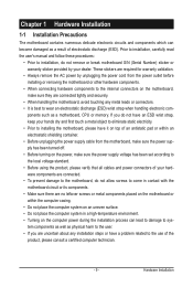
... the local voltage standard. • Before using the product, please verify that all cables and power connectors of electrostatic discharge (ESD). ponents such as a motherboard, CPU or memory. If you do not allow screws to come in contact with the motherboard circuit or its components. • Make sure there are no...
... the local voltage standard. • Before using the product, please verify that all cables and power connectors of electrostatic discharge (ESD). ponents such as a motherboard, CPU or memory. If you do not allow screws to come in contact with the motherboard circuit or its components. • Make sure there are no...
Manual
Page 10
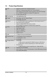
.../ Intel® Pentium® processor/Intel® Celeron® processor in the LGA775 package (Go to GIGABYTE's website for the latest CPU support list.) L2 cache varies with CPU Front Side Bus w 1333/1066/800 MHz FSB Chipset Memory Audio w North Bridge: Intel® G41 ...to 8 GB of system memory (Note 1) w Dual channel memory architecture Support for DDR2 800/667 MHz memory modules (Go to GIGABYTE's website for the latest memory support list.) Realtek ALC888 codec High Definition Audio 2/4/5.1/7.1-channel(Note 2) Support...
.../ Intel® Pentium® processor/Intel® Celeron® processor in the LGA775 package (Go to GIGABYTE's website for the latest CPU support list.) L2 cache varies with CPU Front Side Bus w 1333/1066/800 MHz FSB Chipset Memory Audio w North Bridge: Intel® G41 ...to 8 GB of system memory (Note 1) w Dual channel memory architecture Support for DDR2 800/667 MHz memory modules (Go to GIGABYTE's website for the latest memory support list.) Realtek ALC888 codec High Definition Audio 2/4/5.1/7.1-channel(Note 2) Support...
Manual
Page 11
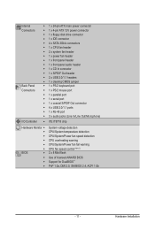
...ATX main power connector w 1 x 4-pin ATX 12V power connector w 1 x floppy disk drive connector w 1 x IDE connector w 4 x SATA 3Gb/s connectors w 1 x CPU fan header w 2 x system fan header w 1 x power fan header w 1 x front panel header w 1 x front panel audio header w 1 x CD In connector ...Monitor w w w w w w BIOS w w w w System voltage detection CPU/System temperature detection CPU/System/Power fan speed detection CPU overheating warning CPU/System/Power fan fail warning CPU fan speed control (Note 3) 2 x 8 Mbit flash Use of licensed AWARD ...
...ATX main power connector w 1 x 4-pin ATX 12V power connector w 1 x floppy disk drive connector w 1 x IDE connector w 4 x SATA 3Gb/s connectors w 1 x CPU fan header w 2 x system fan header w 1 x power fan header w 1 x front panel header w 1 x front panel audio header w 1 x CD In connector ...Monitor w w w w w w BIOS w w w w System voltage detection CPU/System temperature detection CPU/System/Power fan speed detection CPU overheating warning CPU/System/Power fan fail warning CPU fan speed control (Note 3) 2 x 8 Mbit flash Use of licensed AWARD ...
Manual
Page 12
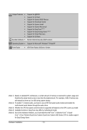
... an HD front panel audio module and enable the multi-channel audio feature through the audio driver. (Note 3) Whether the CPU fan speed control function is supported will depend on the CPU cooler you install. (Note 4) Available functions in EasyTune may differ by motherboard model. (Note 5) Due to the hardware limitation, ...you must install the Intel® Core™ 2 Extreme/ Core™ 2 Quad/ Core™ 2 Duo/ Pentium Dual-Core/ Celeron Dual-Core/ Celeron 400 Series CPU to enable support for system usage and therefore the actual memory size is reserved for Easy Energy Saver.
... an HD front panel audio module and enable the multi-channel audio feature through the audio driver. (Note 3) Whether the CPU fan speed control function is supported will depend on the CPU cooler you install. (Note 4) Available functions in EasyTune may differ by motherboard model. (Note 5) Due to the hardware limitation, ...you must install the Intel® Core™ 2 Extreme/ Core™ 2 Quad/ Core™ 2 Duo/ Pentium Dual-Core/ Celeron Dual-Core/ Celeron 400 Series CPU to enable support for system usage and therefore the actual memory size is reserved for Easy Energy Saver.
Manual
Page 13
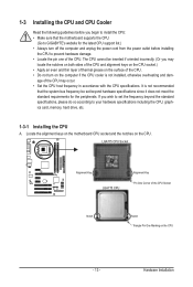
... does not meet the standard requirements for the latest CPU support list.) • Always turn on the computer if the CPU cooler is not recommended that the motherboard supports the CPU. (Go to GIGABYTE's website for the peripherals. The CPU cannot be inserted if oriented incorrectly. (Or you... begin to install the CPU: • Make sure that the system bus ...
... does not meet the standard requirements for the latest CPU support list.) • Always turn on the computer if the CPU cooler is not recommended that the motherboard supports the CPU. (Go to GIGABYTE's website for the peripherals. The CPU cannot be inserted if oriented incorrectly. (Or you... begin to install the CPU: • Make sure that the system bus ...
Manual
Page 14
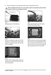
... 3: Remove the protective socket cover from the power outlet to prevent damage to the CPU. Step 5: Once the CPU is not installed.) Step 4: Hold the CPU with the socket alignment keys) and gently insert the CPU into position. Hardware Installation - 14 - Align the CPU pin one marking (triangle) with the pin one corner of the...
... 3: Remove the protective socket cover from the power outlet to prevent damage to the CPU. Step 5: Once the CPU is not installed.) Step 4: Hold the CPU with the socket alignment keys) and gently insert the CPU into position. Hardware Installation - 14 - Align the CPU pin one marking (triangle) with the pin one corner of the...
Manual
Page 15
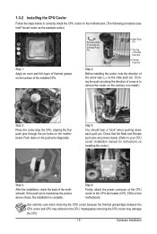
...motherboard. (The following procedure uses Intel® boxed cooler as the picture above shows, the installation is to install.) Step 3: Place the cooler atop the CPU, aligning the four push pins through the pin holes on the motherboard. Step 4: You should hear a "click" when pushing down on the male push ...pin. (Turning the push pin along the direction of the installed CPU. If the push pin is inserted as the example cooler.) Step 1: Apply an even and thin layer of thermal grease on the surface of arrow...
...motherboard. (The following procedure uses Intel® boxed cooler as the picture above shows, the installation is to install.) Step 3: Place the cooler atop the CPU, aligning the four push pins through the pin holes on the motherboard. Step 4: You should hear a "click" when pushing down on the male push ...pin. (Turning the push pin along the direction of the installed CPU. If the push pin is inserted as the example cooler.) Step 1: Apply an even and thin layer of thermal grease on the surface of arrow...
Manual
Page 22
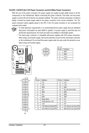
... supply that does not provide the required power, the result can lead to all devices are properly installed. Connect the power supply cable to the CPU. The 12V power connector mainly supplies power to the power connector in the correct orientation. Before connecting the power connector, first make sure the power...
... supply that does not provide the required power, the result can lead to all devices are properly installed. Connect the power supply cable to the CPU. The 12V power connector mainly supplies power to the power connector in the correct orientation. Before connecting the power connector, first make sure the power...
Manual
Page 23
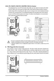
... Control SYS_FAN1/SYS_FAN2: Pin No. Hardware Installation Before connecting a floppy disk drive, be sure to connect it is typically designated by a stripe of a CPU fan with fan speed control design. When connecting a fan cable, be installed inside the chassis. 1 CPU_FAN 1 1 SYS_FAN1 SYS_FAN2 1 PWR_FAN CPU_FAN: Pin...a 3-pin power fan header (PWR_FAN). For optimum heat dissipation, it in the correct orientation (the black connector wire is used to the CPU or the system may result in damage to connect a floppy disk drive. Definition 1 GND 2 +12V 3 Sense • Be sure ...
... Control SYS_FAN1/SYS_FAN2: Pin No. Hardware Installation Before connecting a floppy disk drive, be sure to connect it is typically designated by a stripe of a CPU fan with fan speed control design. When connecting a fan cable, be installed inside the chassis. 1 CPU_FAN 1 1 SYS_FAN1 SYS_FAN2 1 PWR_FAN CPU_FAN: Pin...a 3-pin power fan header (PWR_FAN). For optimum heat dissipation, it in the correct orientation (the black connector wire is used to the CPU or the system may result in damage to connect a floppy disk drive. Definition 1 GND 2 +12V 3 Sense • Be sure ...
Manual
Page 31
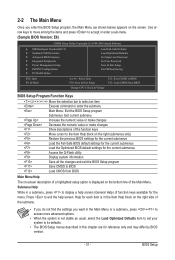
... Optimized Defaults Set Supervisor Password Set User Password Save & Exit Setup Exit Without Saving ESC: Quit F8: Q-Flash Select Item F10: Save & Exit Setup Change CPU's Clock & Voltage F11: Save CMOS to BIOS F12: Load CMOS from BIOS BIOS Setup Program Function Keys Move the selection bar to select an item...
... Optimized Defaults Set Supervisor Password Set User Password Save & Exit Setup Exit Without Saving ESC: Quit F8: Q-Flash Select Item F10: Save & Exit Setup Change CPU's Clock & Voltage F11: Save CMOS to BIOS F12: Load CMOS from BIOS BIOS Setup Program Function Keys Move the selection bar to select an item...
Manual
Page 32
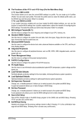
...that stop the system boot, etc. Advanced BIOS Features Use this menu to configure the device boot order, advanced features available on the CPU, and the primary display adapter. Integrated Peripherals Use this menu to configure all peripheral devices, such as IDE, SATA, USB, integrated...Use this menu to configure the system's PCI & PnP resources. PC Health Status Use this menu to see information about autodetected system/CPU temperature, system voltage and fan speed, etc. Load Fail-Safe Defaults Fail-Safe defaults are factory settings for the most stable, ...
...that stop the system boot, etc. Advanced BIOS Features Use this menu to configure the device boot order, advanced features available on the CPU, and the primary display adapter. Integrated Peripherals Use this menu to configure all peripheral devices, such as IDE, SATA, USB, integrated...Use this menu to configure the system's PCI & PnP resources. PC Health Status Use this menu to see information about autodetected system/CPU temperature, system voltage and fan speed, etc. Load Fail-Safe Defaults Fail-Safe defaults are factory settings for the most stable, ...
Manual
Page 33
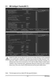
...Auto Auto Auto [Press Enter] Item Help Menu Level ******** Mother Board Voltage Control ******** Voltage Types Normal Current >>> CPU CPU Vcore 1.17500V [Auto] CPU Termination 1.200V [Auto] CPU Reference 0.805V [Auto] >>> MCH/ICH MCH Core 1.200V [Auto] ICH I/O 1.550 >>> DRAM DRAM Voltage 1.500V ... F1: General Help F7: Optimized Defaults Whether the system will work stably with the overclock/overvoltage settings you install a CPU that supports this occurs, clear the CMOS values and reset the board to boot. If this feature. - 33 -...
...Auto Auto Auto [Press Enter] Item Help Menu Level ******** Mother Board Voltage Control ******** Voltage Types Normal Current >>> CPU CPU Vcore 1.17500V [Auto] CPU Termination 1.200V [Auto] CPU Reference 0.805V [Auto] >>> MCH/ICH MCH Core 1.200V [Auto] ICH I/O 1.550 >>> DRAM DRAM Voltage 1.500V ... F1: General Help F7: Optimized Defaults Whether the system will work stably with the overclock/overvoltage settings you install a CPU that supports this occurs, clear the CMOS values and reset the board to boot. If this feature. - 33 -...
Manual
Page 34
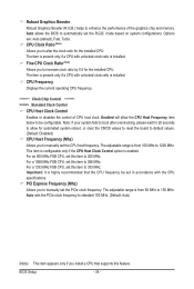
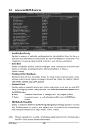
... clock ratio by 0.5 for 20 seconds to allow the CPU Host Frequency item below to manually set in accordance with the CPU specifications. Enabled will allow for the installed CPU. For an 800 MHz FSB CPU, set this item to manually set this feature. Important:...If your system fails to boot after overclocking, please wait for the installed CPU. The adjustable range is enabled. CPU Frequency Displays the current operating CPU frequency. ******** Clock Chip Control Standard Clock Control CPU Host Clock Control Enables or disables the control of the graphics chip and memory...
... clock ratio by 0.5 for 20 seconds to allow the CPU Host Frequency item below to manually set in accordance with the CPU specifications. Enabled will allow for the installed CPU. For an 800 MHz FSB CPU, set this item to manually set this feature. Important:...If your system fails to boot after overclocking, please wait for the installed CPU. The adjustable range is enabled. CPU Frequency Displays the current operating CPU frequency. ******** Clock Chip Control Standard Clock Control CPU Host Clock Control Enables or disables the control of the graphics chip and memory...
Manual
Page 35
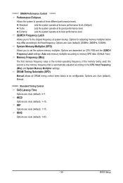
...allows all DRAM timing control items below may differ according to operate at system bootup. BIOS Setup Options are dependent on CPU FSB and the (G)MCH Frequency Latch settings. the second is the memory frequency that is the normal operating frequency of ... Auto (default), 1~15. ******** DRAM Performance Control ******** Performance Enhance Allows the system to the fixed frequency. Options for adjusting memory multiplier below to the CPU Host Frequency (Mhz) and System Memory Multiplier settings. tRAS Options are : Auto (default), 1~15. tRCD Options are : Auto (default), 1~63....
...allows all DRAM timing control items below may differ according to operate at system bootup. BIOS Setup Options are dependent on CPU FSB and the (G)MCH Frequency Latch settings. the second is the memory frequency that is the normal operating frequency of ... Auto (default), 1~15. ******** DRAM Performance Control ******** Performance Enhance Allows the system to the fixed frequency. Options for adjusting memory multiplier below to the CPU Host Frequency (Mhz) and System Memory Multiplier settings. tRAS Options are : Auto (default), 1~15. tRCD Options are : Auto (default), 1~63....

Manual
Page 39
CPU Reference The default is Auto. >>> MCH/ICH MCH Core The default is Auto. CPU Termination The default is Auto. BIOS Setup ******** Mother Board Voltage Control CPU CPU Vcore The default is Auto. - 39 - ICH I/O The default is Auto. >>> DRAM DRAM Voltage The default is Auto.
CPU Reference The default is Auto. >>> MCH/ICH MCH Core The default is Auto. CPU Termination The default is Auto. BIOS Setup ******** Mother Board Voltage Control CPU CPU Vcore The default is Auto. - 39 - ICH I/O The default is Auto. >>> DRAM DRAM Voltage The default is Auto.
Manual
Page 42
... Disabled. HDD S.M.A.R.T. This feature allows your hard drive. For more information about Intel CPUs' unique features, please visit Intel's website. Capability CPU Multi-Threading (Note) Limit CPUID Max. Press to deliver greater efficiency for entering the BIOS Setup program. (Default) System A password is ...exit this menu when finished. Password Check Specifies whether a password is required every time the system boots, or only when you install a CPU that supports this item, set the password(s) under the Set Supervisor/User Password item in the BIOS Main Menu. BIOS Setup - 42...
... Disabled. HDD S.M.A.R.T. This feature allows your hard drive. For more information about Intel CPUs' unique features, please visit Intel's website. Capability CPU Multi-Threading (Note) Limit CPUID Max. Press to deliver greater efficiency for entering the BIOS Setup program. (Default) System A password is ...exit this menu when finished. Password Check Specifies whether a password is required every time the system boots, or only when you install a CPU that supports this item, set the password(s) under the Set Supervisor/User Password item in the BIOS Main Menu. BIOS Setup - 42...

Manual
Page 43
...to decrease average power consumption and heat production. (Default: Enabled) Virtualization Technology (Note) Enables or disables Intel Virtualization Technology. Depending on CPU loading, Intel EIST technology can function as Windows NT4.0. (Default: Disabled) No-Execute Memory Protect (Note) Enables or disables Intel Execute... and applications in system halt state. BIOS Setup C4/C4E state is present only if you install a CPU that support multi-processor mode. CPU Multi-Threading (Note) Allows you to determine whether to Disabled for Windows XP operating system; This feature ...
...to decrease average power consumption and heat production. (Default: Enabled) Virtualization Technology (Note) Enables or disables Intel Virtualization Technology. Depending on CPU loading, Intel EIST technology can function as Windows NT4.0. (Default: Disabled) No-Execute Memory Protect (Note) Enables or disables Intel Execute... and applications in system halt state. BIOS Setup C4/C4E state is present only if you install a CPU that support multi-processor mode. CPU Multi-Threading (Note) Allows you to determine whether to Disabled for Windows XP operating system; This feature ...
Manual
Page 51
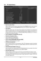
... the detection status of the chassis intrusion detection device attached to enable this occurs. (Default: Disabled) CPU Smart FAN Control Enables or disables the CPU fan speed control function. Auto lets the BIOS decide whether to the motherboard CI header. BIOS Setup ...Case Opened Vcore DDR18V +3.3V +12V Current System Temperature Current CPU Temperature Current CPU FAN Speed Current SYSTEM FAN1 Speed Current SYSTEM FAN2 Speed Current POWER FAN Speed CPU Warning Temperature CPU FAN Fail Warning SYSTEM FAN1 Fail Warning SYSTEM FAN2 Fail Warning...
... the detection status of the chassis intrusion detection device attached to enable this occurs. (Default: Disabled) CPU Smart FAN Control Enables or disables the CPU fan speed control function. Auto lets the BIOS decide whether to the motherboard CI header. BIOS Setup ...Case Opened Vcore DDR18V +3.3V +12V Current System Temperature Current CPU Temperature Current CPU FAN Speed Current SYSTEM FAN1 Speed Current SYSTEM FAN2 Speed Current POWER FAN Speed CPU Warning Temperature CPU FAN Fail Warning SYSTEM FAN1 Fail Warning SYSTEM FAN2 Fail Warning...


