Manual
Page 1
GA-P35C-DS3R/ GA-P35C-DS3/ GA-P35C-S3 LGA775 socket motherboard for Intel® CoreTM processor family/ Intel® Pentium® processor family/Intel® Celeron® processor family User's Manual Rev. 2002 12ME-P35CDS3R-2002R * The WEEE marking on the product indicates this product must not be disposed of with user's other household waste and must be handed over to a designated collection point for the recycling of waste electrical and electronic equipment!! * The WEEE marking applies only in European Union's member states.
GA-P35C-DS3R/ GA-P35C-DS3/ GA-P35C-S3 LGA775 socket motherboard for Intel® CoreTM processor family/ Intel® Pentium® processor family/Intel® Celeron® processor family User's Manual Rev. 2002 12ME-P35CDS3R-2002R * The WEEE marking on the product indicates this product must not be disposed of with user's other household waste and must be handed over to a designated collection point for the recycling of waste electrical and electronic equipment!! * The WEEE marking applies only in European Union's member states.
Manual
Page 3
..., read the Quick Installation Guide included with the product. „ For detailed product information, carefully read the User's Manual. „ For instructions on our website. GIGABYTE UNITED INC. For example, "REV: 1.0" means the revision of the motherboard is the property of GIGABYTE branded motherboards. All rights reserved. Documentation Classifications In order to their respective owners.
..., read the Quick Installation Guide included with the product. „ For detailed product information, carefully read the User's Manual. „ For instructions on our website. GIGABYTE UNITED INC. For example, "REV: 1.0" means the revision of the motherboard is the property of GIGABYTE branded motherboards. All rights reserved. Documentation Classifications In order to their respective owners.
Manual
Page 6
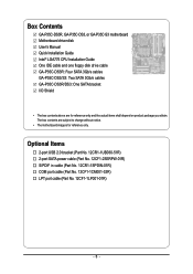
Box Contents GA-P35C-DS3R, GA-P35C-DS3, or GA-P35C-S3 motherboard Motherboard driver disk User's Manual Quick Installation Guide Intel® LGA775 CPU Installation Guide One IDE cable and one floppy disk drive cable GA-P35C-DS3R: Four SATA 3Gb/s cables GA-P35C-DS3/S3: Two SATA 3Gb/s cables GA-P35C-DS3R/DS3: One SATA bracket I/O Shield • The box contents above are subject to change without...
Box Contents GA-P35C-DS3R, GA-P35C-DS3, or GA-P35C-S3 motherboard Motherboard driver disk User's Manual Quick Installation Guide Intel® LGA775 CPU Installation Guide One IDE cable and one floppy disk drive cable GA-P35C-DS3R: Four SATA 3Gb/s cables GA-P35C-DS3/S3: Two SATA 3Gb/s cables GA-P35C-DS3R/DS3: One SATA bracket I/O Shield • The box contents above are subject to change without...
Manual
Page 9
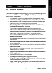
...read the user's manual and follow these procedures: • Prior to wear an electrostatic discharge (ESD) wrist strap when handling electronic components such as a motherboard, CPU or memory. Hardware Installation English Chapter 1 Hardware Installation 1-1 Installation Precautions The motherboard contains numerous delicate electronic...well as physical harm to the user. • If you are connected tightly and securely. • When handling the motherboard, avoid touching any installation steps or have a problem related to the use of electrostatic discharge (ESD). These stickers are ...
...read the user's manual and follow these procedures: • Prior to wear an electrostatic discharge (ESD) wrist strap when handling electronic components such as a motherboard, CPU or memory. Hardware Installation English Chapter 1 Hardware Installation 1-1 Installation Precautions The motherboard contains numerous delicate electronic...well as physical harm to the user. • If you are connected tightly and securely. • When handling the motherboard, avoid touching any installation steps or have a problem related to the use of electrostatic discharge (ESD). These stickers are ...
Manual
Page 15
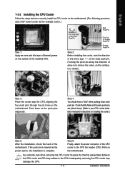
...and Female push pins are joined closely. (Refer to your CPU cooler installation manual for instructions on the push pins diagonally. Use extreme care when removing the...3: Place the cooler atop the CPU, aligning the four push pins through the pin holes on the motherboard. If the push pin is inserted as the example cooler.) Step 1: Apply an even and thin layer... of thermal grease on the surface of the motherboard. Step 4: You should hear a "click" when pushing down on installing the cooler.) Step 5: After the ...
...and Female push pins are joined closely. (Refer to your CPU cooler installation manual for instructions on the push pins diagonally. Use extreme care when removing the...3: Place the cooler atop the CPU, aligning the four push pins through the pin holes on the motherboard. If the push pin is inserted as the example cooler.) Step 1: Apply an even and thin layer... of thermal grease on the surface of the motherboard. Step 4: You should hear a "click" when pushing down on installing the cooler.) Step 5: After the ...
Manual
Page 18
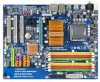
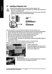
...the following guidelines before installing an expansion card to install an expansion card: • Make sure the motherboard supports the expansion card. Carefully read the manual that supports your operating system. PCI Express x1 Slot PCI Express x16 Slot PCI Slot Follow the steps...: Installing and Removing a PCI Express x16 Graphics Card: • Installing a Graphics Card: Gently insert the graphics card into the slot. 4. GA-P35C-DS3R/DS3/S3 Motherboard - 18 - Align the card with a screw. 5. Secure the card's metal bracket to make any required BIOS changes for your expansion card....
...the following guidelines before installing an expansion card to install an expansion card: • Make sure the motherboard supports the expansion card. Carefully read the manual that supports your operating system. PCI Express x1 Slot PCI Express x16 Slot PCI Slot Follow the steps...: Installing and Removing a PCI Express x16 Graphics Card: • Installing a Graphics Card: Gently insert the graphics card into the slot. 4. GA-P35C-DS3R/DS3/S3 Motherboard - 18 - Align the card with a screw. 5. Secure the card's metal bracket to make any required BIOS changes for your expansion card....
Manual
Page 30
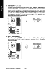
... the S/PDIF digital audio cable, carefully read the manual for your motherboard to certain expansion cards like graphics cards and sound cards. Pin No. For example, some graphics cards may require you to use a S/PDIF digital audio cable for digital audio output from your motherboard to your graphics card if you wish to... 1 1 SPDIFO 2 GND 16) SPDIF_I (S/PDIF In Header) This header supports digital S/PDIF in cable, please contact the local dealer. 1 Pin No. Definition 1 Power 2 SPDIFI 3 GND GA-P35C-DS3R/DS3/S3 Motherboard - 30 -
... the S/PDIF digital audio cable, carefully read the manual for your motherboard to certain expansion cards like graphics cards and sound cards. Pin No. For example, some graphics cards may require you to use a S/PDIF digital audio cable for digital audio output from your motherboard to your graphics card if you wish to... 1 1 SPDIFO 2 GND 16) SPDIF_I (S/PDIF In Header) This header supports digital S/PDIF in cable, please contact the local dealer. 1 Pin No. Definition 1 Power 2 SPDIFI 3 GND GA-P35C-DS3R/DS3/S3 Motherboard - 30 -

Manual
Page 32
... the CMOS values to clear the CMOS values (e.g. Failure to do so may cause damage to the motherboard. • After system restart, go to BIOS Setup to load factory defaults (select Load Optimized Defaults) or manually configure the BIOS settings (refer to Chapter 2, "BIOS Setup," for a few seconds. To clear the CMOS... Definition GND PD6 GND PD7 GND ACKGND BUSY GND PE No Pin SLCT GND 20) CLR_CMOS (Clearing CMOS Jumper) Use this jumper to factory defaults. GA-P35C-DS3R/DS3/S3 Motherboard - 32 -
... the CMOS values to clear the CMOS values (e.g. Failure to do so may cause damage to the motherboard. • After system restart, go to BIOS Setup to load factory defaults (select Load Optimized Defaults) or manually configure the BIOS settings (refer to Chapter 2, "BIOS Setup," for a few seconds. To clear the CMOS... Definition GND PD6 GND PD7 GND ACKGND BUSY GND PE No Pin SLCT GND 20) CLR_CMOS (Clearing CMOS Jumper) Use this jumper to factory defaults. GA-P35C-DS3R/DS3/S3 Motherboard - 32 -

Manual
Page 40
... All, But Disk/Key The system boot will not stop for a keyboard or a floppy disk drive error but it will stop for GA-P35C-DS3R. Extended IDE Drive Configure your IDE/SATA devices by using one of the two methods below : • Auto Lets BIOS automatically detect ...wish to enter the parameters manually, refer to the information on the system. All, But Keyboard The system boot will not stop for a keyboard error but stop for faster system startup. Memory These fields are read-only and are : Disabled (default), Drive A. GA-P35C-DS3R/DS3/S3 Motherboard - 40 - Sector ...
... All, But Disk/Key The system boot will not stop for a keyboard or a floppy disk drive error but it will stop for GA-P35C-DS3R. Extended IDE Drive Configure your IDE/SATA devices by using one of the two methods below : • Auto Lets BIOS automatically detect ...wish to enter the parameters manually, refer to the information on the system. All, But Keyboard The system boot will not stop for a keyboard error but stop for faster system startup. Memory These fields are read-only and are : Disabled (default), Drive A. GA-P35C-DS3R/DS3/S3 Motherboard - 40 - Sector ...
Manual
Page 52
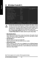
... fails to boot after overclocking, please wait for 20 seconds to allow the CPU Host Frequency item below to be configurable. GA-P35C-DS3R/DS3/S3 Motherboard - 52 - Robust Graphics Booster Robust Graphics Booster (R.G.B.) helps to enhance the performance of CPU host clock. Options are: ...Control (G)MCH OverVoltage Control CPU Voltage Control Normal CPU Vcore ******** [Auto] [16X] [Disabled] 200 Auto [Disabled] [Turbo] [Auto] 667 [Option 1] [Manual] [Normal] [Normal] [Normal] [Normal] [Normal] 1.3875V Item Help Menu Level` KLJI: Move Enter: Select F5: Previous Values +/-/PU/PD: Value...
... fails to boot after overclocking, please wait for 20 seconds to allow the CPU Host Frequency item below to be configurable. GA-P35C-DS3R/DS3/S3 Motherboard - 52 - Robust Graphics Booster Robust Graphics Booster (R.G.B.) helps to enhance the performance of CPU host clock. Options are: ...Control (G)MCH OverVoltage Control CPU Voltage Control Normal CPU Vcore ******** [Auto] [16X] [Disabled] 200 Auto [Disabled] [Turbo] [Auto] 667 [Option 1] [Manual] [Normal] [Normal] [Normal] [Normal] [Normal] 1.3875V Item Help Menu Level` KLJI: Move Enter: Select F5: Previous Values +/-/PU/PD: Value...
Manual
Page 54
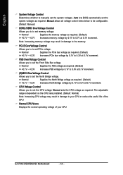
English System Voltage Control Determines whether to manually set memory voltage. PCI-E OverVoltage Control Allows you to 0.3V at 0.1V increment. Normal Supplies the North Bridge voltage as required. (Default) +0.1V ... Auto lets BIOS automatically set the Front Side Bus voltage. Manual allows all voltage control items below to be configurable. (Default: Manual) DDR2 /DDR3 OverVoltage Control Allows you to set the system voltages. FSB OverVoltage Control Allows you to to set the system voltages as required. GA-P35C-DS3R/DS3/S3 Motherboard - 54 -
English System Voltage Control Determines whether to manually set memory voltage. PCI-E OverVoltage Control Allows you to 0.3V at 0.1V increment. Normal Supplies the North Bridge voltage as required. (Default) +0.1V ... Auto lets BIOS automatically set the Front Side Bus voltage. Manual allows all voltage control items below to be configurable. (Default: Manual) DDR2 /DDR3 OverVoltage Control Allows you to set the system voltages. FSB OverVoltage Control Allows you to to set the system voltages as required. GA-P35C-DS3R/DS3/S3 Motherboard - 54 -
Manual
Page 61
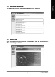
English 3-4 Hardware Information This page provides information about the hardware devices on this motherboard. 3-5 Contact Us Check the contacts information of the GIGABYTE headquarter in Taiwan and the overseas branch offices on the last page of this manual. - 61 - Drivers Installation
English 3-4 Hardware Information This page provides information about the hardware devices on this motherboard. 3-5 Contact Us Check the contacts information of the GIGABYTE headquarter in Taiwan and the overseas branch offices on the last page of this manual. - 61 - Drivers Installation
Manual
Page 72
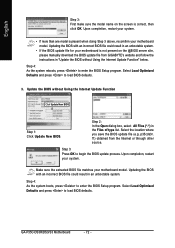
...3: Press OK to load BIOS defaults. 3. Make sure the extracted BIOS file matches your motherboard model. GA-P35C-DS3R/DS3/S3 Motherboard - 72 - Step 4: As the system reboots, press to load BIOS defaults. Step...update file (e.g. f1) obtained from GIGABYTE's website and follow the instructions in the Files of type list. p35cds3r. Upon completion, restart your motherboard is correct, then click OK. ...English Step 3: First make sure the model name on the screen is not present on the @BIOS server site, please manually download...
...3: Press OK to load BIOS defaults. 3. Make sure the extracted BIOS file matches your motherboard model. GA-P35C-DS3R/DS3/S3 Motherboard - 72 - Step 4: As the system reboots, press to load BIOS defaults. Step...update file (e.g. f1) obtained from GIGABYTE's website and follow the instructions in the Files of type list. p35cds3r. Upon completion, restart your motherboard is correct, then click OK. ...English Step 3: First make sure the model name on the screen is not present on the @BIOS server site, please manually download...

Manual
Page 88
...you have prepared the SATA RAID/AHCI driver diskette and configured the required BIOS settings, you need to that you have chosen to manually specify an adapter. Windows Setup Press F6 if you see the next screen. Windows Setup Setup could not determine the type of ... drive(s). Currently, Setup will be a few moments of Windows XP and Vista installation. S=Specify Additional Device ENTER=Continue F3=Exit Figure 2 GA-P35C-DS3R/DS3/S3 Motherboard - 88 - After pressing , there will load support for the following is an example of some files being loaded before you see the ...
...you have prepared the SATA RAID/AHCI driver diskette and configured the required BIOS settings, you need to that you have chosen to manually specify an adapter. Windows Setup Press F6 if you see the next screen. Windows Setup Setup could not determine the type of ... drive(s). Currently, Setup will be a few moments of Windows XP and Vista installation. S=Specify Additional Device ENTER=Continue F3=Exit Figure 2 GA-P35C-DS3R/DS3/S3 Motherboard - 88 - After pressing , there will load support for the following is an example of some files being loaded before you see the ...
Manual
Page 96
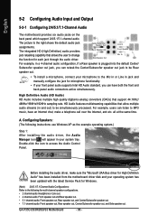
... sure the "Microsoft UAA Bus driver for each jack through the audio driver. GA-P35C-DS3R/DS3/S3 Motherboard - 96 - English 5-2 Configuring Audio Input and Output 5-2-1 Configuring 2/4/5.1/7.1-Channel Audio The motherboard provides six audio jacks on the back panel which support 2/4/5.1/7.1-channel audio. The ...XP as the example operating system.) Step 1: After installing the audio driver, the Audio Manager icon will appear in jack and manually configure the jack for multi-channel speaker configurations. • 2 channel audio: Headphone or Line out. • 4 channel audio...
... sure the "Microsoft UAA Bus driver for each jack through the audio driver. GA-P35C-DS3R/DS3/S3 Motherboard - 96 - English 5-2 Configuring Audio Input and Output 5-2-1 Configuring 2/4/5.1/7.1-Channel Audio The motherboard provides six audio jacks on the back panel which support 2/4/5.1/7.1-channel audio. The ...XP as the example operating system.) Step 1: After installing the audio driver, the Audio Manager icon will appear in jack and manually configure the jack for multi-channel speaker configurations. • 2 channel audio: Headphone or Line out. • 4 channel audio...
Manual
Page 107
...your household waste disposal service or where you purchased the product for activation of the treatment, collection, recycling and disposal procedure. GIGABYTE cannot, however, assume any unauthorized purpose. Restriction of your electrical or electronic equipment is recycled in this text. The separate ...this product must not be disposed of with your product's user's manual and we at the time of life" product, you may contact us at the Customer Care number listed in all GIGABYTE motherboards fulfill European Union regulations for errors or omissions in a manner that...
...your household waste disposal service or where you purchased the product for activation of the treatment, collection, recycling and disposal procedure. GIGABYTE cannot, however, assume any unauthorized purpose. Restriction of your electrical or electronic equipment is recycled in this text. The separate ...this product must not be disposed of with your product's user's manual and we at the time of life" product, you may contact us at the Customer Care number listed in all GIGABYTE motherboards fulfill European Union regulations for errors or omissions in a manner that...


