Manual
Page 10
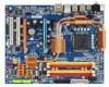
.../s connectors (SATAII0, SATAII1, SATAII2, SATAII3, SATAII4, SATAII5) supporting up to the internal IEEE 1394 header) GA-P35-DS4 Motherboard - 10 - Support for SATA RAID 0, RAID 1, and JBOD Š iTE IT8718 chip: - 1 x floppy disk drive connector supporting up to GIGABYTE's website for the latest memory support list.) Š Realtek ALC889A codec Š High Definition Audio...
.../s connectors (SATAII0, SATAII1, SATAII2, SATAII3, SATAII4, SATAII5) supporting up to the internal IEEE 1394 header) GA-P35-DS4 Motherboard - 10 - Support for SATA RAID 0, RAID 1, and JBOD Š iTE IT8718 chip: - 1 x floppy disk drive connector supporting up to GIGABYTE's website for the latest memory support list.) Š Realtek ALC889A codec Š High Definition Audio...

Manual
Page 16
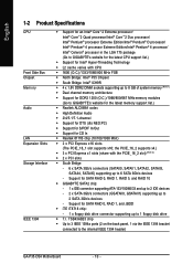
... DDRII2 DDRII3 DDRII4 Due to chipset limitation, read the following guidelines before you are unable to GIGABYTE's website for optimum performance. When enabling Dual Channel mode with two or four memory modules, it is installed. 2. GA-P35-DS4 Motherboard - 16 - DS/SS - - English 1-4 Installing the Memory Read the following guidelines before installing the memory...
... DDRII2 DDRII3 DDRII4 Due to chipset limitation, read the following guidelines before you are unable to GIGABYTE's website for optimum performance. When enabling Dual Channel mode with two or four memory modules, it is installed. 2. GA-P35-DS4 Motherboard - 16 - DS/SS - - English 1-4 Installing the Memory Read the following guidelines before installing the memory...

Manual
Page 28
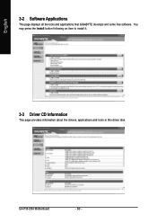
...or RAID 1 configuration requires at least two hard drives. Each SATA connector supports a single SATA device. Each SATA connector supports a single SATA device. Pin No. GA-P35-DS4 Motherboard - 28 - Definition SATAII0 7 1 1 GND 2 TXP 3 TXN 4 GND 5 RXN 1 7 SATAII1 6 RXP 7 GND SATAII4 SATAII2 7 17 ... on configuring a RAID array. Refer to SATA 3Gb/s standard and are compatible with SATA 1.5Gb/s standard. Pin No. The GIGABYTE SATA2 controller supports RAID 0 and RAID 1. Refer to be an even number. Definition 1 GND 2 TXP 3 TXN GSATAII0 4...
...or RAID 1 configuration requires at least two hard drives. Each SATA connector supports a single SATA device. Each SATA connector supports a single SATA device. Pin No. GA-P35-DS4 Motherboard - 28 - Definition SATAII0 7 1 1 GND 2 TXP 3 TXN 4 GND 5 RXN 1 7 SATAII1 6 RXP 7 GND SATAII4 SATAII2 7 17 ... on configuring a RAID array. Refer to SATA 3Gb/s standard and are compatible with SATA 1.5Gb/s standard. Pin No. The GIGABYTE SATA2 controller supports RAID 0 and RAID 1. Refer to be an even number. Definition 1 GND 2 TXP 3 TXN GSATAII0 4...

Manual
Page 44
...Halt (C1E) (Note) Enables or disables Intel® CPU Enhanced Halt (C1E) function, a CPU power-saving function in independent partitions. GA-P35-DS4 Motherboard - 44 - This function may enhance protection for the computer, reducing exposure to Disabled for legacy operating system such as multiple virtual systems.... halt state. With virtualization, one computer system can dynamically and effectively lower the CPU voltage and core frequency to display the GIGABYTE Logo at system startup. to 3 (Note) Allows you install a CPU that supports this item to limit CPUID maximum value...
...Halt (C1E) (Note) Enables or disables Intel® CPU Enhanced Halt (C1E) function, a CPU power-saving function in independent partitions. GA-P35-DS4 Motherboard - 44 - This function may enhance protection for the computer, reducing exposure to Disabled for legacy operating system such as multiple virtual systems.... halt state. With virtualization, one computer system can dynamically and effectively lower the CPU voltage and core frequency to display the GIGABYTE Logo at system startup. to 3 (Note) Allows you install a CPU that supports this item to limit CPUID maximum value...
Manual
Page 60
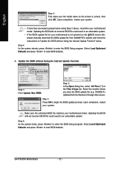
GA-P35-DS4 Motherboard - 60 - English 3-2 Software Applications This page displays all the tools and applications that GIGABYTE develops and some free software. You may press the Install button following an item to install it. 3-3 Driver CD Information This page provides information about the drivers, applications and tools in this driver disk.
GA-P35-DS4 Motherboard - 60 - English 3-2 Software Applications This page displays all the tools and applications that GIGABYTE develops and some free software. You may press the Install button following an item to install it. 3-3 Driver CD Information This page provides information about the drivers, applications and tools in this driver disk.

Manual
Page 68
... v6.00PG, An Energy Star Ally Copyright (C) 1984-2007, Award Software, Inc. English 4-2 BIOS Update Utilities GIGABYTE motherboards provide two unique BIOS update tools, Q-FlashTM and @BIOS .TM GIGABYTE Q-Flash and @BIOS are easy-to-use FAT32/16/12 file system. 3. What is @BIOS ? Before ...BIOS. 4-2-1 Updating the BIOS with caution. During the POST, press the key to your floppy disk, USB flash drive, or hard drive. GA-P35-DS4 Motherboard - 68 - For the sake of going through complicated BIOS flashing process. What is Dual BIOSTM? Restart the system. P35DS4.F1) ...
... v6.00PG, An Energy Star Ally Copyright (C) 1984-2007, Award Software, Inc. English 4-2 BIOS Update Utilities GIGABYTE motherboards provide two unique BIOS update tools, Q-FlashTM and @BIOS .TM GIGABYTE Q-Flash and @BIOS are easy-to-use FAT32/16/12 file system. 3. What is @BIOS ? Before ...BIOS. 4-2-1 Updating the BIOS with caution. During the POST, press the key to your floppy disk, USB flash drive, or hard drive. GA-P35-DS4 Motherboard - 68 - For the sake of going through complicated BIOS flashing process. What is Dual BIOSTM? Restart the system. P35DS4.F1) ...
Manual
Page 72
... then click OK. Step 2: In the Open dialog box, select All Files (*.*) in an unbootable system. P35DS4.f1) obtained from GIGABYTE's website and follow the instructions in "Update the BIOS without Using the Internet Update Function Click Update New BIOS Step 1: Click Update ...system. Select Load Optimized Defaults and press to enter the BIOS Setup program. Step 4: As the system boots, press to load BIOS defaults. GA-P35-DS4 Motherboard - 72 - Step 4: As the system reboots, press to enter the BIOS Setup program. Upon completion, restart your motherboard model. ...
... then click OK. Step 2: In the Open dialog box, select All Files (*.*) in an unbootable system. P35DS4.f1) obtained from GIGABYTE's website and follow the instructions in "Update the BIOS without Using the Internet Update Function Click Update New BIOS Step 1: Click Update ...system. Select Load Optimized Defaults and press to enter the BIOS Setup program. Step 4: As the system boots, press to load BIOS defaults. GA-P35-DS4 Motherboard - 72 - Step 4: As the system reboots, press to enter the BIOS Setup program. Upon completion, restart your motherboard model. ...

Manual
Page 82
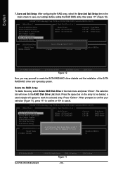
...main screen of Windows operating system for a message which says "Press to enter the GIGABYTE SATA2 RAID BIOS utility. GA-P35-DS4 Motherboard - 82 - Skip this step and proceed to the installation of the GIGABYTE SATA2 RAID BIOS utility (Figure 3), use the up or down arrow key to highlight... a non-RAID configuration. PCIE-to enter RAID Setup Utility ... English C. Configuring a RAID array in the Main Menu block. GIGABYTE Technology Corp. http://www.gigabyte.com.tw HDD0 : HDD1 : ST3120026AS ST3120026AS 120 GB Non-RAID 120 GB Non-RAID ODD0 : DVDROM GO-D1600B Press to ...
...main screen of Windows operating system for a message which says "Press to enter the GIGABYTE SATA2 RAID BIOS utility. GA-P35-DS4 Motherboard - 82 - Skip this step and proceed to the installation of the GIGABYTE SATA2 RAID BIOS utility (Figure 3), use the up or down arrow key to highlight... a non-RAID configuration. PCIE-to enter RAID Setup Utility ... English C. Configuring a RAID array in the Main Menu block. GIGABYTE Technology Corp. http://www.gigabyte.com.tw HDD0 : HDD1 : ST3120026AS ST3120026AS 120 GB Non-RAID 120 GB Non-RAID ODD0 : DVDROM GO-D1600B Press to ...
Manual
Page 84
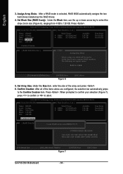
...size which will be used to divide data from 4 KB to the Confirm Creation item. GIGABYTE Technology Corp. English 3. Press . The following are configured, the selection bar automatically jumps to 128 KB. GIGABYTE Technology Corp. Press . Confirm Creation: After all of the array and press . 6. PCIE...SELECTED HARD DISK WILL BE LOST WHEN EXIT WITH SAVING [KL]-Switch Unit [DEL,BS]-Delete Number Figure 7 [ENTER]-Next [ESC]-Abort GA-P35-DS4 Motherboard - 84 - Set Array Size: Under the Size item, enter the size of the items above are typical values: RAID 0-128KB...
...size which will be used to divide data from 4 KB to the Confirm Creation item. GIGABYTE Technology Corp. English 3. Press . The following are configured, the selection bar automatically jumps to 128 KB. GIGABYTE Technology Corp. Press . Confirm Creation: After all of the array and press . 6. PCIE...SELECTED HARD DISK WILL BE LOST WHEN EXIT WITH SAVING [KL]-Switch Unit [DEL,BS]-Delete Number Figure 7 [ENTER]-Next [ESC]-Abort GA-P35-DS4 Motherboard - 84 - Set Array Size: Under the Size item, enter the size of the items above are typical values: RAID 0-128KB...
Manual
Page 86
... settings before exiting the RAID BIOS utility, then press (Figure 10). ARE YOU SURE TO DELETE (Y/N)? GIGABYTE Technology Corp. N RAID Level Capacity Status 0-Stripe 240 GB Normal Members(HDDx) 01 [KL]-Select RAID GA-P35-DS4 Motherboard [SPACE]-Mark Delete [DEL]-Confirm Figure 11 - 86 - [ESC]-Abort Delete the RAID Array:... Model Name ` RDD0: GRAID ALL DATA ON THE RAID WILL LOST!! Press the space bar on the array to mark the selected array. GIGABYTE Technology Corp. a small triangle will move to cancel. The selection bar will appear to be deleted; English 7.
... settings before exiting the RAID BIOS utility, then press (Figure 10). ARE YOU SURE TO DELETE (Y/N)? GIGABYTE Technology Corp. N RAID Level Capacity Status 0-Stripe 240 GB Normal Members(HDDx) 01 [KL]-Select RAID GA-P35-DS4 Motherboard [SPACE]-Mark Delete [DEL]-Confirm Figure 11 - 86 - [ESC]-Abort Delete the RAID Array:... Model Name ` RDD0: GRAID ALL DATA ON THE RAID WILL LOST!! Press the space bar on the array to mark the selected array. GIGABYTE Technology Corp. a small triangle will move to cancel. The selection bar will appear to be deleted; English 7.

Manual
Page 90
... arrow keys to select one minute. S=Specify Additional Device ENTER=Continue F3=Exit Figure 6 GA-P35-DS4 Motherboard - 90 - GIGABYTE GBB363 RAID Controller (Windows 2K/XP/2003) GIGABYTE GBB363 AHCI Controller (Windows 2K/XP/2003) GIGABYTE GBB360 AHCI Controller (Windows 2K/XP/2003) GIGABYTE GBB362 RAID Controller (Windows 2K/XP/2003) ENTER=Select F3=Exit Figure 5 If...
... arrow keys to select one minute. S=Specify Additional Device ENTER=Continue F3=Exit Figure 6 GA-P35-DS4 Motherboard - 90 - GIGABYTE GBB363 RAID Controller (Windows 2K/XP/2003) GIGABYTE GBB363 AHCI Controller (Windows 2K/XP/2003) GIGABYTE GBB360 AHCI Controller (Windows 2K/XP/2003) GIGABYTE GBB362 RAID Controller (Windows 2K/XP/2003) ENTER=Select F3=Exit Figure 5 If...

Manual
Page 94
English GIGABYTE SATA2 controllers: Step 1: Restart your floppy disk (Figure 13). Figure 12 Step 2: Specify the location where the driver is saved, such as your system to that below appears (RAID/AHCI hard drive(s) will not be detected at this stage), select Load Driver. (Figure 12). Figure 13 GA-P35-DS4 Motherboard - 94 - When a screen similar to boot from the Windows Vista setup disk and perform standard OS installation steps.
English GIGABYTE SATA2 controllers: Step 1: Restart your floppy disk (Figure 13). Figure 12 Step 2: Specify the location where the driver is saved, such as your system to that below appears (RAID/AHCI hard drive(s) will not be detected at this stage), select Load Driver. (Figure 12). Figure 13 GA-P35-DS4 Motherboard - 94 - When a screen similar to boot from the Windows Vista setup disk and perform standard OS installation steps.

Manual
Page 104
... A: Make sure your speaker is the light of standby power after the computer shuts down and that's why the light is still on GIGABYTE's website. A: The following Award BIOS beep code descriptions may help you identify possible computer problems. (For reference only.) 1 short: System..., 3 short: Keyboard error 1 long, 9 short: BIOS ROM error Continuous long beeps: Graphics card not inserted properly Continuous short beeps: Power error GA-P35-DS4 Motherboard - 104 - Q: In the BIOS Setup program, why are hidden in Chapter 1. Refer to show the advanced options. Plug in Chapter 1 ...
... A: Make sure your speaker is the light of standby power after the computer shuts down and that's why the light is still on GIGABYTE's website. A: The following Award BIOS beep code descriptions may help you identify possible computer problems. (For reference only.) 1 short: System..., 3 short: Keyboard error 1 long, 9 short: BIOS ROM error Continuous long beeps: Graphics card not inserted properly Continuous short beeps: Power error GA-P35-DS4 Motherboard - 104 - Q: In the BIOS Setup program, why are hidden in Chapter 1. Refer to show the advanced options. Plug in Chapter 1 ...
Manual
Page 112
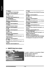
... GIGA-BYTE Technology Co., Ltd. GIGABYTE Global Service System To submit a technical or non-technical (Sales/ Marketing) question, please link to enter the system. GA-P35-DS4 Motherboard - 112 - in CZECH REPUBLIC WEB address : http://www.gigabyte.cz Turkey Representative Office Of GIGA-BYTE... Technology Co., Ltd. TECH. in POLAND WEB address : http://www.gigabyte.pl Ukraine WEB address : http://www.giga...
... GIGA-BYTE Technology Co., Ltd. GIGABYTE Global Service System To submit a technical or non-technical (Sales/ Marketing) question, please link to enter the system. GA-P35-DS4 Motherboard - 112 - in CZECH REPUBLIC WEB address : http://www.gigabyte.cz Turkey Representative Office Of GIGA-BYTE... Technology Co., Ltd. TECH. in POLAND WEB address : http://www.gigabyte.pl Ukraine WEB address : http://www.giga...


