Manual
Page 1
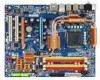
GA-P35-DS4 LGA775 socket motherboard for Intel® CoreTM processor family/ Intel® Pentium® processor family/Intel® Celeron® processor family User's Manual Rev. 2003 12ME-P35DS4-2003R
GA-P35-DS4 LGA775 socket motherboard for Intel® CoreTM processor family/ Intel® Pentium® processor family/Intel® Celeron® processor family User's Manual Rev. 2003 12ME-P35DS4-2003R

Manual
Page 2
Motherboard GA-P35-DS4 Jul. 20, 2007 Motherboard GA-P35-DS4 Jul. 20, 2007
Motherboard GA-P35-DS4 Jul. 20, 2007 Motherboard GA-P35-DS4 Jul. 20, 2007

Manual
Page 3
... in this : "REV: X.X." Disclaimer Information in the use GIGABYTE's unique features, read or download the information on/from the Support\Motherboard\Technology Guide page on your motherboard revision before updating motherboard BIOS, drivers, or when looking for technical information. For example..., "REV: 1.0" means the revision of GIGABYTE. Check your motherboard looks like this manual is protected by GIGA-BYTE TECHNOLOGY CO., LTD as the exclu- sive global distributor of GIGABYTE branded motherboards. Example: The logo is designated by copyright laws...
... in this : "REV: X.X." Disclaimer Information in the use GIGABYTE's unique features, read or download the information on/from the Support\Motherboard\Technology Guide page on your motherboard revision before updating motherboard BIOS, drivers, or when looking for technical information. For example..., "REV: 1.0" means the revision of GIGABYTE. Check your motherboard looks like this manual is protected by GIGA-BYTE TECHNOLOGY CO., LTD as the exclu- sive global distributor of GIGABYTE branded motherboards. Example: The logo is designated by copyright laws...

Manual
Page 4
Table of Contents Box Contents ...6 OptionalItems ...6 GA-P35-DS4 Motherboard Layout 7 Block Diagram ...8 Chapter 1 Hardware Installation 9 1-1 Installation Precautions 9 1-2 Product Specifications 10 1-3 Installing the CPU and CPU Cooler 13 1-3-1 Installing the CPU 13 1-3-2 Installing the CPU ...
Table of Contents Box Contents ...6 OptionalItems ...6 GA-P35-DS4 Motherboard Layout 7 Block Diagram ...8 Chapter 1 Hardware Installation 9 1-1 Installation Precautions 9 1-2 Product Specifications 10 1-3 Installing the CPU and CPU Cooler 13 1-3-1 Installing the CPU 13 1-3-2 Installing the CPU ...
Manual
Page 6
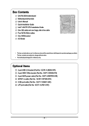
... in cable (Part No. 12CR1-1SPDIN-01R) COM port cable (Part No. 12CF1-1CM001-32R) LPT port cable (Part No. 12CF1-1LP001-01R) - 6 - Box Contents GA-P35-DS4 motherboard Motherboard driver disk User's Manual Quick Installation Guide Intel® LGA775 CPU Installation Guide One IDE cable and one floppy disk drive cable Four SATA 3Gb.../s cables One SATA bracket I/O Shield • The box contents above are subject to change without notice. • The motherboard image is for reference only and the actual items shall depend on product package you obtain.
... in cable (Part No. 12CR1-1SPDIN-01R) COM port cable (Part No. 12CF1-1CM001-32R) LPT port cable (Part No. 12CF1-1LP001-01R) - 6 - Box Contents GA-P35-DS4 motherboard Motherboard driver disk User's Manual Quick Installation Guide Intel® LGA775 CPU Installation Guide One IDE cable and one floppy disk drive cable Four SATA 3Gb.../s cables One SATA bracket I/O Shield • The box contents above are subject to change without notice. • The motherboard image is for reference only and the actual items shall depend on product package you obtain.
Manual
Page 9
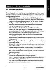
...ESD wrist strap, keep your hands dry and first touch a metal object to eliminate static electricity. • Prior to installing the motherboard, please have a problem related to the use of electrostatic discharge (ESD). If you are no leftover screws or metal components placed on the...supply has been turned off. • Before turning on the power, make sure they are connected tightly and securely. • When handling the motherboard, avoid touching any metal leads or connectors. • It is best to wear an electrostatic discharge (ESD) wrist strap when handling electronic components ...
...ESD wrist strap, keep your hands dry and first touch a metal object to eliminate static electricity. • Prior to installing the motherboard, please have a problem related to the use of electrostatic discharge (ESD). If you are no leftover screws or metal components placed on the...supply has been turned off. • Before turning on the power, make sure they are connected tightly and securely. • When handling the motherboard, avoid touching any metal leads or connectors. • It is best to wear an electrostatic discharge (ESD) wrist strap when handling electronic components ...
Manual
Page 10
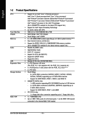
...IEEE 1394 bracket connected to the internal IEEE 1394 header) GA-P35-DS4 Motherboard - 10 - the PCIE_16_2 supports x4.) Š 3 x PCI Express x1 slots (share with CPU Š 1600 (O.C.)/1333/1066/800 MHz FSB Š North Bridge: Intel® P35 Chipset Š South Bridge: Intel® ICH9R Š...174; 4 processor Extreme Edition/Intel® Pentium® 4 processor/ Intel® Celeron® processor in the LGA 775 package (Go to GIGABYTE's website for the latest CPU support list.) Š Support for Intel® Hyper-Threading Technology Š L2 cache varies with the PCIE_16_2 slot...
...IEEE 1394 bracket connected to the internal IEEE 1394 header) GA-P35-DS4 Motherboard - 10 - the PCIE_16_2 supports x4.) Š 3 x PCI Express x1 slots (share with CPU Š 1600 (O.C.)/1333/1066/800 MHz FSB Š North Bridge: Intel® P35 Chipset Š South Bridge: Intel® ICH9R Š...174; 4 processor Extreme Edition/Intel® Pentium® 4 processor/ Intel® Celeron® processor in the LGA 775 package (Go to GIGABYTE's website for the latest CPU support list.) Š Support for Intel® Hyper-Threading Technology Š L2 cache varies with the PCIE_16_2 slot...

Manual
Page 12
... 0.025V increment Š Frequency adjustments in Easytune may differ by 0.05V to : - Adjust PCI Express x16 frequency from 100 MHz to : - GA-P35-DS4 Motherboard - 12 - English BIOS Unique Features Bundled Software Overclocking Operating System Form Factor Š 2 x 8 Mbit flash Š Use of physical memory is...Note 3) Available functions in BIOS Setup (CPU/DDR2/PCIe) allow you to 700 MHz with 1 MHz increment - Increase PCIe voltage by motherboard model. (Note 4) The adjustable CPU voltage range depends on the CPU being used. (Note 5) Due to chipset limitation, Intel ICH9R RAID...
... 0.025V increment Š Frequency adjustments in Easytune may differ by 0.05V to : - Adjust PCI Express x16 frequency from 100 MHz to : - GA-P35-DS4 Motherboard - 12 - English BIOS Unique Features Bundled Software Overclocking Operating System Form Factor Š 2 x 8 Mbit flash Š Use of physical memory is...Note 3) Available functions in BIOS Setup (CPU/DDR2/PCIe) allow you to 700 MHz with 1 MHz increment - Increase PCIe voltage by motherboard model. (Note 4) The adjustable CPU voltage range depends on the CPU being used. (Note 5) Due to chipset limitation, Intel ICH9R RAID...
Manual
Page 13
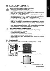
Locate the alignment keys on the motherboard CPU socket and the notches on the CPU Hardware Installation Notch Triangle Pin One Marking on the CPU. If you wish to set beyond the ... 1-3 Installing the CPU and CPU Cooler Read the following guidelines before you begin to install the CPU: • Make sure that the motherboard supports the CPU. (Go to GIGABYTE's website for the latest CPU support list.) • Always turn on the computer if the CPU cooler is optimized for HT Technology •...
Locate the alignment keys on the motherboard CPU socket and the notches on the CPU Hardware Installation Notch Triangle Pin One Marking on the CPU. If you wish to set beyond the ... 1-3 Installing the CPU and CPU Cooler Read the following guidelines before you begin to install the CPU: • Make sure that the motherboard supports the CPU. (Go to GIGABYTE's website for the latest CPU support list.) • Always turn on the computer if the CPU cooler is optimized for HT Technology •...

Manual
Page 14
... turn off the computer and unplug the power cord from the power outlet to prevent damage to correctly install the CPU into its locked position. GA-P35-DS4 Motherboard - 14 - English B. Follow the steps below to the CPU. Step 3: Lift the metal load plate on the CPU socket.
... turn off the computer and unplug the power cord from the power outlet to prevent damage to correctly install the CPU into its locked position. GA-P35-DS4 Motherboard - 14 - English B. Follow the steps below to the CPU. Step 3: Lift the metal load plate on the CPU socket.

Manual
Page 15
... cooler to the CPU fan header (CPU_FAN) on the push pins diagonally. Step 4: You should hear a "click" when pushing down on the motherboard. Hardware Installation Direction of the Arrow Sign on the Male Push Pin Male Push Pin The Top of Female Push Pin Female Push Pin Step...CPU cooler and CPU may damage the CPU. - 15 - Inadequately removing the CPU cooler may adhere to correctly install the CPU cooler on the motherboard. (The following procedure uses Intel® boxed cooler as the picture above, the installation is to your CPU cooler installation manual for instructions on...
... cooler to the CPU fan header (CPU_FAN) on the push pins diagonally. Step 4: You should hear a "click" when pushing down on the motherboard. Hardware Installation Direction of the Arrow Sign on the Male Push Pin Male Push Pin The Top of Female Push Pin Female Push Pin Step...CPU cooler and CPU may damage the CPU. - 15 - Inadequately removing the CPU cooler may adhere to correctly install the CPU cooler on the motherboard. (The following procedure uses Intel® boxed cooler as the picture above, the installation is to your CPU cooler installation manual for instructions on...

Manual
Page 16
... modules, it is recommended that the motherboard supports the memory. GA-P35-DS4 Motherboard - 16 - DS/SS DS/SS (SS=Single-Sided, DS=Double-Sided, "- -"=No Memory) DDRII1 DDRII2 DDRII3 DDRII4 Due to prevent hardware damage. • Memory modules have a foolproof design. The four DDR2 memory sockets are unable to GIGABYTE's website for optimum performance. Dual...
... modules, it is recommended that the motherboard supports the memory. GA-P35-DS4 Motherboard - 16 - DS/SS DS/SS (SS=Single-Sided, DS=Double-Sided, "- -"=No Memory) DDRII1 DDRII2 DDRII3 DDRII4 Due to prevent hardware damage. • Memory modules have a foolproof design. The four DDR2 memory sockets are unable to GIGABYTE's website for optimum performance. Dual...

Manual
Page 17
... socket. Follow the steps below to the memory module. DDR2 DIMMs are not compatible to DDR DIMMs. Be sure to install DDR2 DIMMs on this motherboard.
... socket. Follow the steps below to the memory module. DDR2 DIMMs are not compatible to DDR DIMMs. Be sure to install DDR2 DIMMs on this motherboard.

Manual
Page 18
Turn on the card until it is fully seated in the slot. 3. Install the driver provided with a screw. 5. GA-P35-DS4 Motherboard - 18 - Locate an expansion slot that came with the slot, and press down on your operating system. Make sure the metal contacts on the card ... your computer. PCI Express x16 Slot PCI Express x1 Slot PCI Slot Follow the steps below to install an expansion card: • Make sure the motherboard supports the expansion card. After installing all expansion cards, replace the chassis cover(s). 6. If necessary, go to BIOS Setup to release the card and ...
Turn on the card until it is fully seated in the slot. 3. Install the driver provided with a screw. 5. GA-P35-DS4 Motherboard - 18 - Locate an expansion slot that came with the slot, and press down on your operating system. Make sure the metal contacts on the card ... your computer. PCI Express x16 Slot PCI Express x1 Slot PCI Slot Follow the steps below to install an expansion card: • Make sure the motherboard supports the expansion card. After installing all expansion cards, replace the chassis cover(s). 6. If necessary, go to BIOS Setup to release the card and ...

Manual
Page 19
Hardware Installation When you install two graphics cards, connect the power cable from your power supply to the onboard PCI Express x16 slots. English • The motherboard provides a PCIE_12V power connector, which can supply extra power to this connector. - 19 -
Hardware Installation When you install two graphics cards, connect the power cable from your power supply to the onboard PCI Express x16 slots. English • The motherboard provides a PCIE_12V power connector, which can supply extra power to this connector. - 19 -
Manual
Page 20
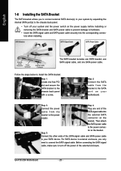
GA-P35-DS4 Motherboard - 20 - English 1-6 Installing the SATA Bracket The SATA bracket allows you only need to the power connec- Then attach the SATA power cable to connect ... bracket and SATA power cable to prevent damage to hardware. • Insert the SATA signal cable and SATA power cable securely into bracket to your motherboard. Follow the steps below to install the SATA bracket: Step 1: Locate one end of the cable from the bracket to the chassis back panel with...
GA-P35-DS4 Motherboard - 20 - English 1-6 Installing the SATA Bracket The SATA bracket allows you only need to the power connec- Then attach the SATA power cable to connect ... bracket and SATA power cable to prevent damage to hardware. • Insert the SATA signal cable and SATA power cable securely into bracket to your motherboard. Follow the steps below to install the SATA bracket: Step 1: Locate one end of the cable from the bracket to the chassis back panel with...

Manual
Page 21
... USB keyboard/mouse, USB printer, USB flash drive and etc. Hardware Installation Use this feature, ensure that your device and then remove it from the motherboard. • When removing the cable, pull it side to side to 1 Gbps data rate. RJ-45 LAN Port The Gigabit Ethernet LAN port provides Internet...
... USB keyboard/mouse, USB printer, USB flash drive and etc. Hardware Installation Use this feature, ensure that your device and then remove it from the motherboard. • When removing the cable, pull it side to side to 1 Gbps data rate. RJ-45 LAN Port The Gigabit Ethernet LAN port provides Internet...
Manual
Page 22
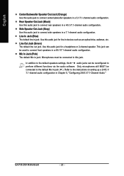
Line Out Jack (Green) The default line out jack. Mic In Jack (Pink) The default Mic in jack. Refer to the default Mic in jack ( ). GA-P35-DS4 Motherboard - 22 - Line In Jack (Blue) The default line in jack. Use this audio jack for line in devices such as an optical drive, walkman, etc. ...
Line Out Jack (Green) The default line out jack. Mic In Jack (Pink) The default Mic in jack. Refer to the default Mic in jack ( ). GA-P35-DS4 Motherboard - 22 - Line In Jack (Blue) The default line in jack. Use this audio jack for line in devices such as an optical drive, walkman, etc. ...

Manual
Page 23
... 17) SPDIF_O 18) SPDIF_IN 19) F_USB1/F_USB2 20) F1_1394 21) COMA 22) LPT 23) CLR_CMOS 24) CI Read the following guidelines before turning on the motherboard. - 23 -
... 17) SPDIF_O 18) SPDIF_IN 19) F_USB1/F_USB2 20) F1_1394 21) COMA 22) LPT 23) CLR_CMOS 24) CI Read the following guidelines before turning on the motherboard. - 23 -
Manual
Page 24
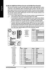
.../Off) GND GND GND -5V +5V +5V +5V (Only for 2x12 pin ATX) GND (Only for 2x4 pin 12V) 7 +12V 8 +12V 12 24 1 13 ATX GA-P35-DS4 Motherboard ATX: Pin No. 1 2 3 4 5 6 7 8 9 10 11 12 Definition Pin No. 3.3V 13 3.3V 14 GND 15 +5V 16 GND 17 +5V 18 GND 19 Power Good... a power supply providing a 2x4 12V and a 2x12 power connector, remove the protective covers from the 12V power connector and the main power connector on the motherboard. If the 12V power connector is not connected, the computer will not start. • Use of the power connector, the power supply can lead to...
.../Off) GND GND GND -5V +5V +5V +5V (Only for 2x12 pin ATX) GND (Only for 2x4 pin 12V) 7 +12V 8 +12V 12 24 1 13 ATX GA-P35-DS4 Motherboard ATX: Pin No. 1 2 3 4 5 6 7 8 9 10 11 12 Definition Pin No. 3.3V 13 3.3V 14 GND 15 +5V 16 GND 17 +5V 18 GND 19 Power Good... a power supply providing a 2x4 12V and a 2x12 power connector, remove the protective covers from the 12V power connector and the main power connector on the motherboard. If the 12V power connector is not connected, the computer will not start. • Use of the power connector, the power supply can lead to...


