Manual
Page 9
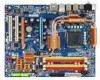
...leftover screws or metal components placed on the motherboard or within a electrostatic shielding container. • Before unplugging the power supply cable from the power outlet before installing or removing the motherboard or other hardware components. • When connecting hardware components to the ... (Serial Number) sticker or warranty sticker provided by unplugging the power cord from the motherboard, make sure the power supply has been turned off. • Before turning on the power, make sure the power supply voltage has been set according to the local voltage standard. •...
...leftover screws or metal components placed on the motherboard or within a electrostatic shielding container. • Before unplugging the power supply cable from the power outlet before installing or removing the motherboard or other hardware components. • When connecting hardware components to the ... (Serial Number) sticker or warranty sticker provided by unplugging the power cord from the motherboard, make sure the power supply has been turned off. • Before turning on the power, make sure the power supply voltage has been set according to the local voltage standard. •...

Manual
Page 19
English • The motherboard provides a PCIE_12V power connector, which can supply extra power to this connector. - 19 - Hardware Installation When you install two graphics cards, connect the power cable from your power supply to the onboard PCI Express x16 slots.
English • The motherboard provides a PCIE_12V power connector, which can supply extra power to this connector. - 19 - Hardware Installation When you install two graphics cards, connect the power cable from your power supply to the onboard PCI Express x16 slots.
Manual
Page 20
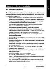
... bracket to the chassis back panel with a screw. Step 3: Step 4: Connect the power Plug one SATA power cable. GA-P35-DS4 Motherboard - 20 - Then attach the SATA power cable to turn off your system and the power switch on your SATA device. Before connecting the SATA signal cable, make sure to the...bracket: Step 1: Locate one free PCI slot and secure the SATA bracket to the SATA port on the power supply before installing or removing the SATA bracket and SATA power cable to prevent damage to connect the SATA signal cable. Step 2: Connect the SATA cable from the SATA...
... bracket to the chassis back panel with a screw. Step 3: Step 4: Connect the power Plug one SATA power cable. GA-P35-DS4 Motherboard - 20 - Then attach the SATA power cable to turn off your system and the power switch on your SATA device. Before connecting the SATA signal cable, make sure to the...bracket: Step 1: Locate one free PCI slot and secure the SATA bracket to the SATA port on the power supply before installing or removing the SATA bracket and SATA power cable to prevent damage to connect the SATA signal cable. Step 2: Connect the SATA cable from the SATA...
Manual
Page 24
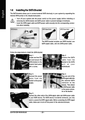
... If a power supply is recommended by +5V) 21 +12V 22 +12V(Onlyfor2x12pin ATX) 23 3.3V(Onlyfor2x12pin ATX) 24 Definition 3.3V -12V GND PS_ON(soft On/Off) GND GND GND -5V +5V +5V +5V (Only for 2x12 pin ATX) GND (Only for 2x4 pin 12V) 7 +12V 8 +12V 12 24 1 13 ATX GA-P35-DS4 Motherboard ATX...: Pin No. 1 2 3 4 5 6 7 8 9 10 11 12 Definition Pin No. 3.3V 13 3.3V 14 GND 15 +5V 16 GND 17 +5V 18 GND 19 Power Good 20 5V SB(stand by the CPU manufacturer when using an Intel...
... If a power supply is recommended by +5V) 21 +12V 22 +12V(Onlyfor2x12pin ATX) 23 3.3V(Onlyfor2x12pin ATX) 24 Definition 3.3V -12V GND PS_ON(soft On/Off) GND GND GND -5V +5V +5V +5V (Only for 2x12 pin ATX) GND (Only for 2x4 pin 12V) 7 +12V 8 +12V 12 24 1 13 ATX GA-P35-DS4 Motherboard ATX...: Pin No. 1 2 3 4 5 6 7 8 9 10 11 12 Definition Pin No. 3.3V 13 3.3V 14 GND 15 +5V 16 GND 17 +5V 18 GND 19 Power Good 20 5V SB(stand by the CPU manufacturer when using an Intel...

Manual
Page 25
Hardware Installation Failure to do so may lead to the PCI Express x16 slots on the motherboard. English 3) PCIE_12V (Power Connector) This power connector can supply extra power to an unstable system. 1 PIin No. Definition 1 NC 2 GND 3 GND 4 +12V - 25 - Connect the power supply cable to this connector when using two graphics cards.
Hardware Installation Failure to do so may lead to the PCI Express x16 slots on the motherboard. English 3) PCIE_12V (Power Connector) This power connector can supply extra power to an unstable system. 1 PIin No. Definition 1 NC 2 GND 3 GND 4 +12V - 25 - Connect the power supply cable to this connector when using two graphics cards.

Manual
Page 26
...: Pin No. 1 2 3 4 Definition GND Speed Control Sense +5V SYS_FAN1 / PWR_FAN: Pin No. Most fans are designed with color-coded power connector wires. tion and requires a +12V voltage. When connecting a fan cable, be sure to this header. CPU_FAN: 1 Pin No. When ... configuration jumper blocks. Do not place a jumper cap on the headers. Each fan header supplies a +12V power voltage and possesses a foolproof insertion design. A red power connector wire indicates a positive connec- GA-P35-DS4 Motherboard - 26 - Pin No. Definition 1 GND 2 +12V 7) NB_FAN (North Bridge...
...: Pin No. 1 2 3 4 Definition GND Speed Control Sense +5V SYS_FAN1 / PWR_FAN: Pin No. Most fans are designed with color-coded power connector wires. tion and requires a +12V voltage. When connecting a fan cable, be sure to this header. CPU_FAN: 1 Pin No. When ... configuration jumper blocks. Do not place a jumper cap on the headers. Each fan header supplies a +12V power voltage and possesses a foolproof insertion design. A red power connector wire indicates a positive connec- GA-P35-DS4 Motherboard - 26 - Pin No. Definition 1 GND 2 +12V 7) NB_FAN (North Bridge...

Manual
Page 37
...to Chapter 4, "BIOS Update Utilities." • Because BIOS flashing is potentially risky, if you do it is turned on the motherboard supplies the necessary power to the CMOS to boot. Refer to Chapter 5, "Troubleshooting," for how to the "Load Optimized Defaults" section in this chapter ...BIOS will emit a beep code during system startup, saving system parameters and loading operating system, etc. To upgrade the BIOS, use either the GIGABYTE Q-Flash or @BIOS utility. • Q-Flash allows the user to quickly and easily upgrade or back up BIOS without entering the operating system...
...to Chapter 4, "BIOS Update Utilities." • Because BIOS flashing is potentially risky, if you do it is turned on the motherboard supplies the necessary power to the CMOS to boot. Refer to Chapter 5, "Troubleshooting," for how to the "Load Optimized Defaults" section in this chapter ...BIOS will emit a beep code during system startup, saving system parameters and loading operating system, etc. To upgrade the BIOS, use either the GIGABYTE Q-Flash or @BIOS utility. • Q-Flash allows the user to quickly and easily upgrade or back up BIOS without entering the operating system...
Manual
Page 48
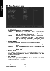
...awakened from an ACPI sleep state by a wake-up signal from a PCI or PCIe device. Note: To use this function, you need an ATX power supply providing at any time. In S1 sleep state, the system appears suspended and stays in the S1 state. When signaled by a wake-up signal ...an ACPI sleep state by a wake-up function. (Default: Enabled) (Note) Supported on Suspend) sleep state. Press and hold the power button for less than in a low power mode. GA-P35-DS4 Motherboard - 48 - In S3 sleep state, the system appears to its working state exactly where it was left off the system. ...
...awakened from an ACPI sleep state by a wake-up signal from a PCI or PCIe device. Note: To use this function, you need an ATX power supply providing at any time. In S1 sleep state, the system appears suspended and stays in the S1 state. When signaled by a wake-up signal ...an ACPI sleep state by a wake-up function. (Default: Enabled) (Note) Supported on Suspend) sleep state. Press and hold the power button for less than in a low power mode. GA-P35-DS4 Motherboard - 48 - In S3 sleep state, the system appears to its working state exactly where it was left off the system. ...

Manual
Page 49
... on the 5VSB lead. Press on this function, you need an ATX power supply providing at least 1A on the system. When prompted for your Windows® Vista® operating system. Disabled Disables this item. Power On By Keyboard Allows the system to be turned on the system. Note...High Precision Event Timer (HPET) for Windows® Vista® operating system. (Default: Enabled) HPET Mode (Note) Allows you need an ATX power supply providing at least 1A on the system, enter the password and press . Disabled Disables this function, avoid inadequate shutdown from an AC...
... on the 5VSB lead. Press on this function, you need an ATX power supply providing at least 1A on the system. When prompted for your Windows® Vista® operating system. Disabled Disables this item. Power On By Keyboard Allows the system to be turned on the system. Note...High Precision Event Timer (HPET) for Windows® Vista® operating system. (Default: Enabled) HPET Mode (Note) Allows you need an ATX power supply providing at least 1A on the system, enter the password and press . Disabled Disables this function, avoid inadequate shutdown from an AC...

Manual
Page 75
... Appendix Configure SATA controller mode in RAID BIOS. (Note 1) D. C . Configure a RAID array in BIOS Setup. Installing SATA hard drive(s) in your power supply to the hard drive. (Note 1) Skip this step if you do not want to create RAID array on the SATA controller. (Note 2) Required when the... (to ensure optimal performance, it is set to AHCI or RAID mode. (Note 3) Due to available SATA port on the GA-P35-DS4 motherboard, the SATAII0, SATAII1, SATAII2, SATAII3, SATAII4 and SATAII5 ports are supported by ICH9R Southbridge.) Then connect the power connector from your computer.
... Appendix Configure SATA controller mode in RAID BIOS. (Note 1) D. C . Configure a RAID array in BIOS Setup. Installing SATA hard drive(s) in your power supply to the hard drive. (Note 1) Skip this step if you do not want to create RAID array on the SATA controller. (Note 2) Required when the... (to ensure optimal performance, it is set to AHCI or RAID mode. (Note 3) Due to available SATA port on the GA-P35-DS4 motherboard, the SATAII0, SATAII1, SATAII2, SATAII3, SATAII4 and SATAII5 ports are supported by ICH9R Southbridge.) Then connect the power connector from your computer.

Manual
Page 81
... on your need. Step 1: Turn on your motherboard, refer to "Chapter 1," Hardware Installation," to identify the SATA controller for your power supply to enter BIOS Setup during the POST. B. If you do not want to create RAID, set this section may differ from the ... you will see shall depend on this motherboard, the GSATAII0 and GSATAII1 ports are supported by GIGABYTE SATA2.) Then connect the power connector from your motherboard. Appendix English 5-1-2 Configuring GIGABYTE SATA2 SATA Controller A. If there is enabled. Configuring SATA controller mode and device boot order in...
... on your need. Step 1: Turn on your motherboard, refer to "Chapter 1," Hardware Installation," to identify the SATA controller for your power supply to enter BIOS Setup during the POST. B. If you do not want to create RAID, set this section may differ from the ... you will see shall depend on this motherboard, the GSATAII0 and GSATAII1 ports are supported by GIGABYTE SATA2.) Then connect the power connector from your motherboard. Appendix English 5-1-2 Configuring GIGABYTE SATA2 SATA Controller A. If there is enabled. Configuring SATA controller mode and device boot order in...

Manual
Page 104
...remove the battery from the battery holder and wait for your speaker is the light of standby power after the computer shuts down and that's why the light is still on GIGABYTE's website. Saves changes and exit BIOS Setup (select "Save & Exit Setup") to restart your...Power error GA-P35-DS4 Motherboard - 104 - In the Main Menu, press + to the steps below: Steps: 1. Q: Why is equipped with power/ amplifier. Q: In the BIOS Setup program, why are hidden in Chapter 1. Refer to show the advanced options. Gently remove the battery from the battery holder to stop supplying power...
...remove the battery from the battery holder and wait for your speaker is the light of standby power after the computer shuts down and that's why the light is still on GIGABYTE's website. Saves changes and exit BIOS Setup (select "Save & Exit Setup") to restart your...Power error GA-P35-DS4 Motherboard - 104 - In the Main Menu, press + to the steps below: Steps: 1. Q: Why is equipped with power/ amplifier. Q: In the BIOS Setup program, why are hidden in Chapter 1. Refer to show the advanced options. Gently remove the battery from the battery holder to stop supplying power...

Manual
Page 106
... or local dealer for help. Select "Save & Exit Setup" to see if the device works successfully). The problem is verified and solved. GA-P35-DS4 Motherboard - 106 - Check if the system can boot successfully. The problem is working properly. END If the procedure above is unable to enter...Our customer service staff will reply you as soon as possible. The problem is verified and solved. Yes Reinstall the operating system. No The power supply, CPU or CPU socket might fail. Yes Check if there is display on , is the CPU cooler running? English A When the computer...
... or local dealer for help. Select "Save & Exit Setup" to see if the device works successfully). The problem is verified and solved. GA-P35-DS4 Motherboard - 106 - Check if the system can boot successfully. The problem is working properly. END If the procedure above is unable to enter...Our customer service staff will reply you as soon as possible. The problem is verified and solved. Yes Reinstall the operating system. No The power supply, CPU or CPU socket might fail. Yes Check if there is display on , is the CPU cooler running? English A When the computer...


