Manual
Page 1
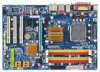
GA-P35-DS3L/ GA-P35-S3L LGA775 socket motherboard for Intel® CoreTM processor family/ Intel® Pentium® processor family/Intel® Celeron® processor family User's Manual Rev. 2001 12ME-P35DS3L-2001R * The WEEE marking on the product indicates this product must not be disposed of with user's other household waste and must be handed over to a designated collection point for the recycling of waste electrical and electronic equipment!! * The WEEE marking applies only in European Union's member states.
GA-P35-DS3L/ GA-P35-S3L LGA775 socket motherboard for Intel® CoreTM processor family/ Intel® Pentium® processor family/Intel® Celeron® processor family User's Manual Rev. 2001 12ME-P35DS3L-2001R * The WEEE marking on the product indicates this product must not be disposed of with user's other household waste and must be handed over to a designated collection point for the recycling of waste electrical and electronic equipment!! * The WEEE marking applies only in European Union's member states.
Manual
Page 3
..., drivers, or when looking for technical information. Changes to the specifications and features in this manual is protected by GIGABYTE without GIGABYTE's prior written permission. No part of GIGABYTE. Check your motherboard looks like this manual are legally registered to GIGABYTE UNITED INC. All rights reserved. Documentation Classifications In order to assist in any means without prior...
..., drivers, or when looking for technical information. Changes to the specifications and features in this manual is protected by GIGABYTE without GIGABYTE's prior written permission. No part of GIGABYTE. Check your motherboard looks like this manual are legally registered to GIGABYTE UNITED INC. All rights reserved. Documentation Classifications In order to assist in any means without prior...
Manual
Page 6
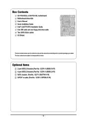
Box Contents GA-P35-DS3L or GA-P35-S3L motherboard Motherboard driver disk User's Manual Quick Installation Guide Intel® LGA775 CPU Installation Guide One IDE cable and one floppy disk drive cable Two SATA 3Gb/s cables I/O Shield The box ...
Box Contents GA-P35-DS3L or GA-P35-S3L motherboard Motherboard driver disk User's Manual Quick Installation Guide Intel® LGA775 CPU Installation Guide One IDE cable and one floppy disk drive cable Two SATA 3Gb/s cables I/O Shield The box ...
Manual
Page 9
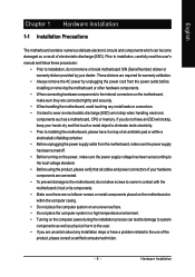
Prior to installation, carefully read the user's manual and follow these procedures: • Prior to installation, do not remove or break motherboard S/N (Serial Number) sticker or warranty sticker provided by unplugging the power cord from the motherboard, make sure the power supply has been turned off. ...have an ESD wrist strap, keep your hands dry and first touch a metal object to eliminate static electricity. • Prior to installing the motherboard, please have a problem related to the use of the product, please consult a certified computer technician. - 9 - If you are uncertain...
Prior to installation, carefully read the user's manual and follow these procedures: • Prior to installation, do not remove or break motherboard S/N (Serial Number) sticker or warranty sticker provided by unplugging the power cord from the motherboard, make sure the power supply has been turned off. ...have an ESD wrist strap, keep your hands dry and first touch a metal object to eliminate static electricity. • Prior to installing the motherboard, please have a problem related to the use of the product, please consult a certified computer technician. - 9 - If you are uncertain...
Manual
Page 15
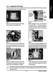
... Before installing the cooler, note the direction of the arrow sign on the male push pin. (Turning the push pin along the direction of the motherboard. If the push pin is inserted as the example cooler.) Step 1: Apply an even and thin layer of thermal grease on installing the cooler.)... the contrary, is complete. Hardware Installation Check that the Male and Female push pins are joined closely. (Refer to your CPU cooler installation manual for instructions on the surface of the CPU cooler to the CPU. Inadequately removing the CPU cooler may adhere to the CPU fan header (...
... Before installing the cooler, note the direction of the arrow sign on the male push pin. (Turning the push pin along the direction of the motherboard. If the push pin is inserted as the example cooler.) Step 1: Apply an even and thin layer of thermal grease on installing the cooler.)... the contrary, is complete. Hardware Installation Check that the Male and Female push pins are joined closely. (Refer to your CPU cooler installation manual for instructions on the surface of the CPU cooler to the CPU. Inadequately removing the CPU cooler may adhere to the CPU fan header (...
Manual
Page 18
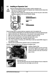
... Example: Installing and Removing a PCI Express x16 Graphics Card: • Installing a Graphics Card: Gently insert the graphics card into the slot. 4. GA-P35-DS3L/S3L Motherboard - 18 - Locate an expansion slot that came with the expansion card in the slot. 3. After installing all expansion cards, replace the chassis cover... card with the slot, and press down on your operating system. Install the driver provided with your card. Carefully read the manual that supports your expansion card. • Always turn off the computer and unplug the power cord from the power outlet before ...
... Example: Installing and Removing a PCI Express x16 Graphics Card: • Installing a Graphics Card: Gently insert the graphics card into the slot. 4. GA-P35-DS3L/S3L Motherboard - 18 - Locate an expansion slot that came with the expansion card in the slot. 3. After installing all expansion cards, replace the chassis cover... card with the slot, and press down on your operating system. Install the driver provided with your card. Carefully read the manual that supports your expansion card. • Always turn off the computer and unplug the power cord from the power outlet before ...

Manual
Page 28
... cards. For information about connecting the S/PDIF digital audio cable, carefully read the manual for digital audio output from your motherboard to your expansion card. Pin No. For purchasing the optional USB bracket, please contact the local dealer. GA-P35-DS3L/S3L Motherboard - 28 - English 15) SPDIF_O (S/PDIF Out Header) This header supports digital S/PDIF out...
... cards. For information about connecting the S/PDIF digital audio cable, carefully read the manual for digital audio output from your motherboard to your expansion card. Pin No. For purchasing the optional USB bracket, please contact the local dealer. GA-P35-DS3L/S3L Motherboard - 28 - English 15) SPDIF_O (S/PDIF Out Header) This header supports digital S/PDIF out...

Manual
Page 29
... Setup," for a few seconds. English 17) CI (Chassis Intrusion Header) This motherboard provides a chassis detection feature that detects if the chassis cover has been removed. Failure to do so may cause damage to the motherboard. • After system restart, go to BIOS Setup to load factory defaults (...select Load Optimized Defaults) or manually configure the BIOS settings (refer to clear the CMOS values (e.g. To clear the ...
... Setup," for a few seconds. English 17) CI (Chassis Intrusion Header) This motherboard provides a chassis detection feature that detects if the chassis cover has been removed. Failure to do so may cause damage to the motherboard. • After system restart, go to BIOS Setup to load factory defaults (...select Load Optimized Defaults) or manually configure the BIOS settings (refer to clear the CMOS values (e.g. To clear the ...
Manual
Page 36
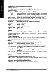
... all other errors. Typically, 640 KB will stop for a floppy disk drive error but it will be reserved for all other errors. GA-P35-DS3L/S3L Motherboard - 36 - English IDE Channel 2, 3 Master, IDE Channel 4 Master/Slave IDE Auto-Detection Press to autodetect the parameters of the ...boot will stop . Options are : None, 360K/5.25", 1.2M/5.25", 720K/3.5", 1.44M/3.5", 2.88M/3.5". If you wish to enter the parameters manually, refer to the information on Allows you to None. Floppy 3 Mode Support Allows you to selects the type of cylinders. Landing Zone Landing zone...
... all other errors. Typically, 640 KB will stop for a floppy disk drive error but it will be reserved for all other errors. GA-P35-DS3L/S3L Motherboard - 36 - English IDE Channel 2, 3 Master, IDE Channel 4 Master/Slave IDE Auto-Detection Press to autodetect the parameters of the ...boot will stop . Options are : None, 360K/5.25", 1.2M/5.25", 720K/3.5", 1.44M/3.5", 2.88M/3.5". If you wish to enter the parameters manually, refer to the information on Allows you to None. Floppy 3 Mode Support Allows you to selects the type of cylinders. Landing Zone Landing zone...

Manual
Page 48
...Option 1 or Option 2 to help make your system more stable. Option 1 Option 2 Memory Timing Configuration 1. (Default) Memory Timing Configuration 2. GA-P35-DS3L/S3L Motherboard - 48 - For a 1066 MHz FSB CPU, set this item to set the system memory multiplier. Increases CPU frequency by 17% or ...Multiplier settings. Increases CPU frequency by 9% or 11% depending on CPU loading. English CPU Host Frequency (Mhz) Allows you to manually set the PCIe clock frequency. Standard Turbo Lets the system operate at its good performance level. (Default) Extreme Lets the system ...
...Option 1 or Option 2 to help make your system more stable. Option 1 Option 2 Memory Timing Configuration 1. (Default) Memory Timing Configuration 2. GA-P35-DS3L/S3L Motherboard - 48 - For a 1066 MHz FSB CPU, set this item to set the system memory multiplier. Increases CPU frequency by 17% or ...Multiplier settings. Increases CPU frequency by 9% or 11% depending on CPU loading. English CPU Host Frequency (Mhz) Allows you to manually set the PCIe clock frequency. Standard Turbo Lets the system operate at its good performance level. (Default) Extreme Lets the system ...

Manual
Page 55
Drivers Installation English 3-4 Hardware Information This page provides information about the hardware devices on this motherboard. 3-5 Contact Us Check the contacts information of the GIGABYTE headquarter in Taiwan and the overseas branch offices on the last page of this manual. - 55 -
Drivers Installation English 3-4 Hardware Information This page provides information about the hardware devices on this motherboard. 3-5 Contact Us Check the contacts information of the GIGABYTE headquarter in Taiwan and the overseas branch offices on the last page of this manual. - 55 -
Manual
Page 66
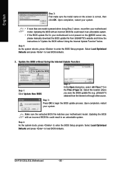
... Optimized Defaults and press to begin the BIOS update process. Upon completion, restart your motherboard model. Make sure the extracted BIOS file matches your motherboard is correct, then click OK. GA-P35-DS3L/S3L Motherboard - 66 - p35ds3l.f1) obtained from GIGABYTE's website and follow the instructions in an unbootable system. Step 3: Press OK to...Setup program. English Step 3: First make sure the model name on the screen is not present on the @BIOS server site, please manually download the BIOS update file from the Internet or through other source.
... Optimized Defaults and press to begin the BIOS update process. Upon completion, restart your motherboard model. Make sure the extracted BIOS file matches your motherboard is correct, then click OK. GA-P35-DS3L/S3L Motherboard - 66 - p35ds3l.f1) obtained from GIGABYTE's website and follow the instructions in an unbootable system. Step 3: Press OK to...Setup program. English Step 3: First make sure the model name on the screen is not present on the @BIOS server site, please manually download the BIOS update file from the Internet or through other source.
Manual
Page 69
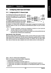
... out jack, you can retask the Center/Subwoofer speaker out jack to be simultaneously processed. Side Speaker Out Mic In For example, in jack and manually configure the jack for multi-channel speaker configurations. • 2 channel audio: Headphone or Line out. • 4 channel audio: Front speaker out ...- The picture to the right shows the default audio jack assignments. English Chapter 5 Appendix 5-1 Configuring Audio Input and Output 5-1-1 Configuring 2/4/5.1/7.1-Channel Audio The motherboard provides six audio jacks on the back panel which support 2/4/5.1/7.1-channel audio.
... out jack, you can retask the Center/Subwoofer speaker out jack to be simultaneously processed. Side Speaker Out Mic In For example, in jack and manually configure the jack for multi-channel speaker configurations. • 2 channel audio: Headphone or Line out. • 4 channel audio: Front speaker out ...- The picture to the right shows the default audio jack assignments. English Chapter 5 Appendix 5-1 Configuring Audio Input and Output 5-1-1 Configuring 2/4/5.1/7.1-Channel Audio The motherboard provides six audio jacks on the back panel which support 2/4/5.1/7.1-channel audio.


