
Manual
Page 1
GA-P31-DS3/ GA-P31-DS3L/ GA-P31-S3L LGA775 socket motherboard for Intel® CoreTM processor family/ Intel® Pentium® processor family/Intel® Celeron® processor family User's Manual Rev. 1001 12ME-P31DS3-1001R * The WEEE marking on the product indicates this product must not be disposed of with user's other household waste and must be handed over to a designated collection point for the recycling of waste electrical and electronic equipment!! * The WEEE marking applies only in European Union's member states.
GA-P31-DS3/ GA-P31-DS3L/ GA-P31-S3L LGA775 socket motherboard for Intel® CoreTM processor family/ Intel® Pentium® processor family/Intel® Celeron® processor family User's Manual Rev. 1001 12ME-P31DS3-1001R * The WEEE marking on the product indicates this product must not be disposed of with user's other household waste and must be handed over to a designated collection point for the recycling of waste electrical and electronic equipment!! * The WEEE marking applies only in European Union's member states.

Manual
Page 10
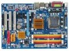
...® Pentium® 4 processor/ Intel® Celeron® processor in the LGA 775 package (Go to GIGABYTE's website for the latest CPU support list.) Š Support for Intel® Hyper-Threading Technology Š L2... 4 x 1.8V DDR2 DIMM sockets supporting up to 4 GB of system memory (Note 1) Š Dual channel memory architecture Š Support for DDR2 800/667 MHz memory modules (Note 2) (Go to GIGABYTE's website for the latest memory ... brackets connected to the internal USB headers) "*" Only the GA-P31-DS3/DS3L adopts All-Solid Capacitor design. GA-P31-DS3/DS3L/S3L Motherboard - 10 -
...® Pentium® 4 processor/ Intel® Celeron® processor in the LGA 775 package (Go to GIGABYTE's website for the latest CPU support list.) Š Support for Intel® Hyper-Threading Technology Š L2... 4 x 1.8V DDR2 DIMM sockets supporting up to 4 GB of system memory (Note 1) Š Dual channel memory architecture Š Support for DDR2 800/667 MHz memory modules (Note 2) (Go to GIGABYTE's website for the latest memory ... brackets connected to the internal USB headers) "*" Only the GA-P31-DS3/DS3L adopts All-Solid Capacitor design. GA-P31-DS3/DS3L/S3L Motherboard - 10 -

Manual
Page 13
...for HT Technology • A BIOS that supports HT Technology and has it does not meet the standard requirements for the peripherals. LGA775 CPU Socket Alignment Key LGA 775 CPU Alignment Key Pin One Corner of the CPU. Hyper-Threading Technology System Requirements: (Go to Intel's website for ...Cooler Read the following guidelines before you begin to install the CPU: • Make sure that the motherboard supports the CPU. (Go to GIGABYTE's website for the latest CPU support list.) • Always turn on the CPU Hardware Installation The CPU cannot be set the frequency beyond hardware...
...for HT Technology • A BIOS that supports HT Technology and has it does not meet the standard requirements for the peripherals. LGA775 CPU Socket Alignment Key LGA 775 CPU Alignment Key Pin One Corner of the CPU. Hyper-Threading Technology System Requirements: (Go to Intel's website for ...Cooler Read the following guidelines before you begin to install the CPU: • Make sure that the motherboard supports the CPU. (Go to GIGABYTE's website for the latest CPU support list.) • Always turn on the CPU Hardware Installation The CPU cannot be set the frequency beyond hardware...

Manual
Page 14
...insert the CPU into its locked position. Step 5: Once the CPU is properly inserted, replace the load plate and push the CPU socket lever back into position. GA-P31-DS3/DS3L/S3L Motherboard - 14 - Before installing the CPU, make sure to turn off the computer and unplug the power cord from the ...power outlet to prevent damage to correctly install the CPU into the motherboard CPU socket. Align the CPU pin one marking (triangle) with ...
...insert the CPU into its locked position. Step 5: Once the CPU is properly inserted, replace the load plate and push the CPU socket lever back into position. GA-P31-DS3/DS3L/S3L Motherboard - 14 - Before installing the CPU, make sure to turn off the computer and unplug the power cord from the ...power outlet to prevent damage to correctly install the CPU into the motherboard CPU socket. Align the CPU pin one marking (triangle) with ...

Manual
Page 16
... GA-P31-DS3/DS3L/S3L Motherboard - 16 - If you begin to chipset limitation, read the following : Channel 0: DDRII1, DDRII2 Dual Channel Memory Configurations Table DDRII1 DDRII2 DDRII3 DDRII4 Channel 1: DDRII3, DDRII4 Two Modules DS/SS - - The four DDR2 memory sockets are... unable to start or incorrect detection of memory modules. DS/SS DS/SS - - - - DS/SS (SS=Single-Sided, DS=Double-Sided, "- -"=No Memory) Memory configurations below , system instability or unexpected results may occur. SS SS - - Dual Channel mode cannot be used . (Go to GIGABYTE...
... GA-P31-DS3/DS3L/S3L Motherboard - 16 - If you begin to chipset limitation, read the following : Channel 0: DDRII1, DDRII2 Dual Channel Memory Configurations Table DDRII1 DDRII2 DDRII3 DDRII4 Channel 1: DDRII3, DDRII4 Two Modules DS/SS - - The four DDR2 memory sockets are... unable to start or incorrect detection of memory modules. DS/SS DS/SS - - - - DS/SS (SS=Single-Sided, DS=Double-Sided, "- -"=No Memory) Memory configurations below , system instability or unexpected results may occur. SS SS - - Dual Channel mode cannot be used . (Go to GIGABYTE...

Manual
Page 17
...has a notch, so it vertically into place when the memory module is securely inserted. - 17 - Spread the retaining clips at both ends of the socket will snap into the memory socket. Step 1: Note the orientation of the memory, push down on this motherboard. Step 2: The clips at both ends of the memory... socket. As indicated in the picture on the left, place your memory modules in one direction. Follow the steps below to correctly install your fingers on...
...has a notch, so it vertically into place when the memory module is securely inserted. - 17 - Spread the retaining clips at both ends of the socket will snap into the memory socket. Step 1: Note the orientation of the memory, push down on this motherboard. Step 2: The clips at both ends of the memory... socket. As indicated in the picture on the left, place your memory modules in one direction. Follow the steps below to correctly install your fingers on...

Manual
Page 77
... to start the computer. A (Continued...) - 77 - Connect the ATX main power cable and the 12V power cable. No Correctly insert the memory into the memory socket. Appendix Remove all peripherals, connecting cables, and power cord etc. Select "Save & Exit Setup" to solve the problem. Make sure the motherboard does not short...
... to start the computer. A (Continued...) - 77 - Connect the ATX main power cable and the 12V power cable. No Correctly insert the memory into the memory socket. Appendix Remove all peripherals, connecting cables, and power cord etc. Select "Save & Exit Setup" to solve the problem. Make sure the motherboard does not short...
Manual
Page 78
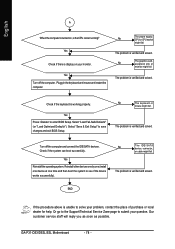
No The power supply, CPU or CPU socket might fail. Yes Reinstall the operating system. Reinstall other devices one by one (install one device at one time and then boot the system to ... the CPU cooler running? Our customer service staff will reply you as soon as possible. No The IDE/SATA device, connector, or cable might fail. GA-P31-DS3/DS3L/S3L Motherboard - 78 - Yes Press to solve your problem, contact the place of purchase or local dealer for help. English A When the computer is...
No The power supply, CPU or CPU socket might fail. Yes Reinstall the operating system. Reinstall other devices one by one (install one device at one time and then boot the system to ... the CPU cooler running? Our customer service staff will reply you as soon as possible. No The IDE/SATA device, connector, or cable might fail. GA-P31-DS3/DS3L/S3L Motherboard - 78 - Yes Press to solve your problem, contact the place of purchase or local dealer for help. English A When the computer is...

