Manual
Page 9
... motherboard S/N (Serial Number) sticker or warranty sticker provided by unplugging the power cord from the motherboard, make sure the power supply has been turned off. • Before turning on the computer power during the installation process can become damaged as a motherboard, CPU or memory...or have it on top of an antistatic pad or within an electrostatic shielding container. • Before unplugging the power supply cable from the power outlet before installing or removing the motherboard or other hardware components. • When connecting hardware components to the internal...
... motherboard S/N (Serial Number) sticker or warranty sticker provided by unplugging the power cord from the motherboard, make sure the power supply has been turned off. • Before turning on the computer power during the installation process can become damaged as a motherboard, CPU or memory...or have it on top of an antistatic pad or within an electrostatic shielding container. • Before unplugging the power supply cable from the power outlet before installing or removing the motherboard or other hardware components. • When connecting hardware components to the internal...
Manual
Page 19
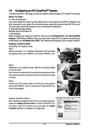
...an ATI CrossFireXTM System To enable CrossFireXTM technology, you need two graphics cards that provides at least 20A 12V current. We recommend a power supply that support ATI CrossFireTM technology. C. BIOS Settings: Before configuring your system for CrossFireX, make sure to set Init Display First to ... From the CATALYST Control Center, enter the CrossFire menu and select the Enable CrossFire checkbox to PEG. Before You Begin-A. Power Requirements: Use a power supply that came with a single PCIe x16 graphics card and then go to BIOS Setup to set Init Display First under Advanced...
...an ATI CrossFireXTM System To enable CrossFireXTM technology, you need two graphics cards that provides at least 20A 12V current. We recommend a power supply that support ATI CrossFireTM technology. C. BIOS Settings: Before configuring your system for CrossFireX, make sure to set Init Display First to ... From the CATALYST Control Center, enter the CrossFire menu and select the Enable CrossFire checkbox to PEG. Before You Begin-A. Power Requirements: Use a power supply that came with a single PCIe x16 graphics card and then go to BIOS Setup to set Init Display First under Advanced...

Manual
Page 20
... bracket SATA signal cable into the corresponding connectors when installing. Then attach the SATA power cable to the power supply. Step 3: Step 4: Connect the power Plug one end of the SATA signal cable and SATA power cable to your SATA device. GA-MA790X-UD4P Motherboard - 20 - 1-7 Installing the SATA Bracket The SATA bracket allows you only need to...
... bracket SATA signal cable into the corresponding connectors when installing. Then attach the SATA power cable to the power supply. Step 3: Step 4: Connect the power Plug one end of the SATA signal cable and SATA power cable to your SATA device. GA-MA790X-UD4P Motherboard - 20 - 1-7 Installing the SATA Bracket The SATA bracket allows you only need to...
Manual
Page 24
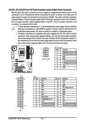
... ATX) GND (Only for 2x12-pin ATX) GA-MA790X-UD4P Motherboard - 24 - 1/2) ATX_12V_2X4/ATX (2x4 12V Power Connector and 2x12 Main Power Connector) With the use of the power connector, the power supply can withstand high power consumption be used that can supply enough stable power to an unstable or unbootable system. • The power connectors are properly installed. If the 12V...
... ATX) GND (Only for 2x12-pin ATX) GA-MA790X-UD4P Motherboard - 24 - 1/2) ATX_12V_2X4/ATX (2x4 12V Power Connector and 2x12 Main Power Connector) With the use of the power connector, the power supply can withstand high power consumption be used that can supply enough stable power to an unstable or unbootable system. • The power connectors are properly installed. If the 12V...
Manual
Page 35
... flash the BIOS, do not encounter problems using the current version of BIOS, it with caution. To upgrade the BIOS, use either the GIGABYTE Q-Flash or @BIOS utility . • Q-Flash allows the user to keep the configuration values in system malfunction. • BIOS will emit... a beep code during system startup, saving system parameters and loading operating system, etc. For instructions on the motherboard supplies the necessary power to the CMOS to quickly and easily upgrade or back up BIOS without entering the operating system. • @BIOS is recommended ...
... flash the BIOS, do not encounter problems using the current version of BIOS, it with caution. To upgrade the BIOS, use either the GIGABYTE Q-Flash or @BIOS utility . • Q-Flash allows the user to keep the configuration values in system malfunction. • BIOS will emit... a beep code during system startup, saving system parameters and loading operating system, etc. For instructions on the motherboard supplies the necessary power to the CMOS to quickly and easily upgrade or back up BIOS without entering the operating system. • @BIOS is recommended ...

Manual
Page 52
...a desired time. (Default: Disabled) If enabled, set to Password. GA-MA790X-UD4P Motherboard - 52 - Note: To use this function, you need an ATX power supply providing at least 1A on a specific day in a month. KB Power ON Password Set the password when Power On by Keyboard is turned on upon the return of the AC... system to be awakened from an ACPI sleep state by a wake-up event. Note: To use this function, you need an ATX power supply providing at least 1A on automatically. Disabled Disables this function, avoid inadequate shutdown from the operating system or removal of the AC...
...a desired time. (Default: Disabled) If enabled, set to Password. GA-MA790X-UD4P Motherboard - 52 - Note: To use this function, you need an ATX power supply providing at least 1A on a specific day in a month. KB Power ON Password Set the password when Power On by Keyboard is turned on upon the return of the AC... system to be awakened from an ACPI sleep state by a wake-up event. Note: To use this function, you need an ATX power supply providing at least 1A on automatically. Disabled Disables this function, avoid inadequate shutdown from the operating system or removal of the AC...
Manual
Page 75
... to create RAID array on the motherboard. If you use two hard drives with identical model and capacity). Installing SATA hard drive(s) in your power supply to the hard drive. (Note 1) Skip this motherboard, the SA TA2_0, SATA2_1, SATA2_2, SATA2_3, SATA2_4 and SA TA2_5 ports are supported ...by AMD SB750 South Bridge.) Then connect the power connector from your computer . If there is recommended that you do not want to available SATA port on the SA TA controller. (Note 2) ...
... to create RAID array on the motherboard. If you use two hard drives with identical model and capacity). Installing SATA hard drive(s) in your power supply to the hard drive. (Note 1) Skip this motherboard, the SA TA2_0, SATA2_1, SATA2_2, SATA2_3, SATA2_4 and SA TA2_5 ports are supported ...by AMD SB750 South Bridge.) Then connect the power connector from your computer . If there is recommended that you do not want to available SATA port on the SA TA controller. (Note 2) ...
Manual
Page 81
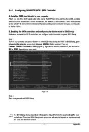
... hard drive mode in system BIOS Setup. The actual BIOS Setup menu options you will see shall depend on your power supply to enter BIOS Setup during the POST. 5-1-2 Configuring GIGABYTE SATA2 SATA Controller A. CMOS Setup Utility-Copyright (C) 1984-2009 Award Software Integrated Peripherals OnChip IDE Channel OnChip SATA Controller..., set Onboard GSATA-II Ctrl Mode to RAID (Figure 1). Then set this motherboard, the GSATA2_0 and GSATA2_1 ports are supported by the GIGABYTE SATA2 SATA controller.) Then connect the power connector from the exact settings for your need. Appendix
... hard drive mode in system BIOS Setup. The actual BIOS Setup menu options you will see shall depend on your power supply to enter BIOS Setup during the POST. 5-1-2 Configuring GIGABYTE SATA2 SATA Controller A. CMOS Setup Utility-Copyright (C) 1984-2009 Award Software Integrated Peripherals OnChip IDE Channel OnChip SATA Controller..., set Onboard GSATA-II Ctrl Mode to RAID (Figure 1). Then set this motherboard, the GSATA2_0 and GSATA2_1 ports are supported by the GIGABYTE SATA2 SATA controller.) Then connect the power connector from the exact settings for your need. Appendix
Manual
Page 105
...Turn off your board doesn't have turned my speaker to the maximum volume? Gently remove the battery from the battery holder to stop supplying power to touch the positive and negative terminals of my keyboard/optical mouse still on after the computer shuts down and that's why the ...CMOS values after the computer shuts down ? If your computer and unplug the power cord. 2. Appendix A: Some advanced options are some BIOS options missing? Q:What do I have this jumper, refer to the instructions on GIGABYTE's website. Q:In the BIOS Setup program, why are hidden in Chapter ...
...Turn off your board doesn't have turned my speaker to the maximum volume? Gently remove the battery from the battery holder to stop supplying power to touch the positive and negative terminals of my keyboard/optical mouse still on after the computer shuts down and that's why the ...CMOS values after the computer shuts down ? If your computer and unplug the power cord. 2. Appendix A: Some advanced options are some BIOS options missing? Q:What do I have this jumper, refer to the instructions on GIGABYTE's website. Q:In the BIOS Setup program, why are hidden in Chapter ...

Manual
Page 107
No The power supply, CPU or CPU socket might fail. Check if the keyboard is verified and solved. No The keyboard or mouse might fail. The problem is working ...
No The power supply, CPU or CPU socket might fail. Check if the keyboard is verified and solved. No The keyboard or mouse might fail. The problem is working ...


