Manual
Page 4
... ...6 GA-MA790X-DS4 Motherboard Layout 7 Block Diagram ...8 Chapter 1 Hardware Installation 9 1-1 Installation Precautions 9 1-2 Product Specifications 10 1-3 Installing the CPU and CPU Cooler 13 1-3-1 Installing the CPU 13 1-3-2 Installing the CPU Cooler 15 1-4 Installing the Memory 16 1-4-1 Dual Channel Memory Configuration 16 1-4-2 Installing a Memory 17 1-5 Installing an Expansion Card 18 1-6 Back Panel Connectors 20 1-7 Internal Connectors 22 Chapter 2 BIOS Setup 35 2-1 Startup Screen 36 2-2 The Main Menu 37 2-3 Standard CMOS Features 39 2-4 Advanced BIOS Features...
... ...6 GA-MA790X-DS4 Motherboard Layout 7 Block Diagram ...8 Chapter 1 Hardware Installation 9 1-1 Installation Precautions 9 1-2 Product Specifications 10 1-3 Installing the CPU and CPU Cooler 13 1-3-1 Installing the CPU 13 1-3-2 Installing the CPU Cooler 15 1-4 Installing the Memory 16 1-4-1 Dual Channel Memory Configuration 16 1-4-2 Installing a Memory 17 1-5 Installing an Expansion Card 18 1-6 Back Panel Connectors 20 1-7 Internal Connectors 22 Chapter 2 BIOS Setup 35 2-1 Startup Screen 36 2-2 The Main Menu 37 2-3 Standard CMOS Features 39 2-4 Advanced BIOS Features...
Manual
Page 10
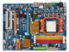
...via the USB brackets connected to 4 SATA 3Gb/s devices - The PCI Express x16 slots conform to PCI Express 2.0 standard.) 3 x PCI Express x1 slots 2 x PCI slots South Bridge: - 1 x IDE connector supporting ATA-133/100/66/33 and up to 2 IDE devices - 4 x SATA 3Gb/s connectors supporting up to the internal USB headers) GA-MA790X-DS4 Motherboard - 10 - Support for SATA RAID 0, RAID 1, and RAID 10 iTE IT8718 chip: - 1 x floppy disk drive connector supporting up to GIGABYTE's website for the latest memory support list.) Realtek ALC889A codec High Definition Audio 2/4/5.1/7.1-channel Support for...
...via the USB brackets connected to 4 SATA 3Gb/s devices - The PCI Express x16 slots conform to PCI Express 2.0 standard.) 3 x PCI Express x1 slots 2 x PCI slots South Bridge: - 1 x IDE connector supporting ATA-133/100/66/33 and up to 2 IDE devices - 4 x SATA 3Gb/s connectors supporting up to the internal USB headers) GA-MA790X-DS4 Motherboard - 10 - Support for SATA RAID 0, RAID 1, and RAID 10 iTE IT8718 chip: - 1 x floppy disk drive connector supporting up to GIGABYTE's website for the latest memory support list.) Realtek ALC889A codec High Definition Audio 2/4/5.1/7.1-channel Support for...

Manual
Page 11
... ATX 12V power connector Š 1 x 4-pin PCIe 12V power connector Š 1 x floppy disk drive connector Š 1 x IDE connector Š 4 x SATA 3Gb/s connectors Š 1 x CPU fan header Š 2 x system fan headers Š 1 x power fan header Š 1 x North Bridge fan header Š 1 x front panel header Š 1 x front panel audio header Š 1 x CD In connector Š 1 x S/PDIF In header Š 1 x S/PDIF Out header Š 1 x IEEE 1394a header Š 2 x USB 2.0/1.1 headers Š 1 x parallel port header Š 1 x chassis intrusion header Š 1 x power LED...
... ATX 12V power connector Š 1 x 4-pin PCIe 12V power connector Š 1 x floppy disk drive connector Š 1 x IDE connector Š 4 x SATA 3Gb/s connectors Š 1 x CPU fan header Š 2 x system fan headers Š 1 x power fan header Š 1 x North Bridge fan header Š 1 x front panel header Š 1 x front panel audio header Š 1 x CD In connector Š 1 x S/PDIF In header Š 1 x S/PDIF Out header Š 1 x IEEE 1394a header Š 2 x USB 2.0/1.1 headers Š 1 x parallel port header Š 1 x chassis intrusion header Š 1 x power LED...
Manual
Page 12
... PCI Express frequency from 200 MHz to Windows XP 32-bit operating system limitation, when more than 4 GB of physical memory is installed, the actual memory size displayed will operate in x8 mode. GA-MA790X-DS4 Motherboard - 12 - Increase CPU voltage (Note 5) - Increase DDR2 voltage by 0.025V to 0.3750V with 0.025V increment Š Frequency adjustments in BIOS Setup (CPU/HT Link/PCIE/DDR2) allow you are installing a single PCI Express x16 graphics card, please install it in the PCIE_16_1 slot...
... PCI Express frequency from 200 MHz to Windows XP 32-bit operating system limitation, when more than 4 GB of physical memory is installed, the actual memory size displayed will operate in x8 mode. GA-MA790X-DS4 Motherboard - 12 - Increase CPU voltage (Note 5) - Increase DDR2 voltage by 0.025V to 0.3750V with 0.025V increment Š Frequency adjustments in BIOS Setup (CPU/HT Link/PCIE/DDR2) allow you are installing a single PCI Express x16 graphics card, please install it in the PCIE_16_1 slot...
Manual
Page 16
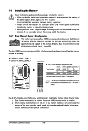
... damage. • Memory modules have a foolproof design. 1-4 Installing the Memory Read the following guidelines before you are unable to insert the memory, switch the direction. 1-4-1 Dual Channel Memory Configuration This motherboard provides four DDR2 memory sockets and supports Dual Channel Technology. After the memory is recommended that memory of the same capacity, brand, speed, and chips be used and installed in Dual Channel mode. 1. When enabling Dual Channel mode with two or four memory modules, it is installed, the BIOS will double...
... damage. • Memory modules have a foolproof design. 1-4 Installing the Memory Read the following guidelines before you are unable to insert the memory, switch the direction. 1-4-1 Dual Channel Memory Configuration This motherboard provides four DDR2 memory sockets and supports Dual Channel Technology. After the memory is recommended that memory of the same capacity, brand, speed, and chips be used and installed in Dual Channel mode. 1. When enabling Dual Channel mode with two or four memory modules, it is installed, the BIOS will double...
Manual
Page 18
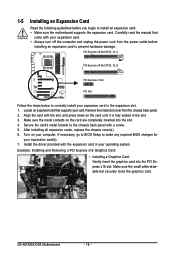
... card in the slot. 3. If necessary, go to BIOS Setup to correctly install your computer. Example: Installing and Removing a PCI Express x16 Graphics Card: • Installing a Graphics Card: Gently insert the graphics card into the slot. 4. Carefully read the manual that supports your expansion card. • Always turn off the computer and unplug the power cord from the chassis back panel. 2. Locate an expansion slot that came with a screw. 5. After installing all expansion cards, replace the chassis cover(s). 6. Remove the metal slot...
... card in the slot. 3. If necessary, go to BIOS Setup to correctly install your computer. Example: Installing and Removing a PCI Express x16 Graphics Card: • Installing a Graphics Card: Gently insert the graphics card into the slot. 4. Carefully read the manual that supports your expansion card. • Always turn off the computer and unplug the power cord from the chassis back panel. 2. Locate an expansion slot that came with a screw. 5. After installing all expansion cards, replace the chassis cover(s). 6. Remove the metal slot...
Manual
Page 24
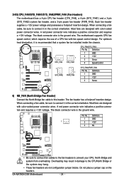
... with fan speed control design. GA-MA790X-DS4 Motherboard - 24 - For optimum heat dissipation, it in damage to the CPU/North Bridge or the system may hang. • These fan headers are designed with color-coded power connector wires. When connecting a fan cable, be sure to prevent your CPU, North Bridge and system from overheating. The black connector wire is the ground wire. When connecting a fan cable, be installed inside the chassis. 1 CPU_FAN 1 SYS_FAN1 CPU_FAN/SYS_FAN1: Pin...
... with fan speed control design. GA-MA790X-DS4 Motherboard - 24 - For optimum heat dissipation, it in damage to the CPU/North Bridge or the system may hang. • These fan headers are designed with color-coded power connector wires. When connecting a fan cable, be sure to prevent your CPU, North Bridge and system from overheating. The black connector wire is the ground wire. When connecting a fan cable, be installed inside the chassis. 1 CPU_FAN 1 SYS_FAN1 CPU_FAN/SYS_FAN1: Pin...
Manual
Page 28
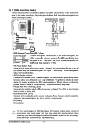
... the speaker on the chassis front panel. When connecting your system using the power switch (refer to Chapter 2, "BIOS Setup," "Power Management Setup," for information about beep codes. • HD (IDE Hard Drive Activity LED, Blue) Connects to turn off when the system is detected, the BIOS may differ by issuing a beep code. 13) F_PANEL (Front Panel Header) Connect the power switch, reset switch, speaker and system status indicator on the chassis front panel to this header, make sure the wire assignments and the pin...
... the speaker on the chassis front panel. When connecting your system using the power switch (refer to Chapter 2, "BIOS Setup," "Power Management Setup," for information about beep codes. • HD (IDE Hard Drive Activity LED, Blue) Connects to turn off when the system is detected, the BIOS may differ by issuing a beep code. 13) F_PANEL (Front Panel Header) Connect the power switch, reset switch, speaker and system status indicator on the chassis front panel to this header, make sure the wire assignments and the pin...

Manual
Page 38
..., hard drive types, floppy disk drive types, and the type of errors that stop the system boot, etc. „ Advanced BIOS Features Use this menu to configure the device boot order, advanced features available on the CPU, and the primary display adapter. „ Integrated Peripherals Use this menu to configure all peripheral devices, such as IDE, SATA, USB, integrated audio, and integrated LAN, etc. „ Power Management Setup Use this menu to configure all the power-saving functions. „ PnP/PCI Configurations Use this menu to configure the...
..., hard drive types, floppy disk drive types, and the type of errors that stop the system boot, etc. „ Advanced BIOS Features Use this menu to configure the device boot order, advanced features available on the CPU, and the primary display adapter. „ Integrated Peripherals Use this menu to configure all peripheral devices, such as IDE, SATA, USB, integrated audio, and integrated LAN, etc. „ Power Management Setup Use this menu to configure all the power-saving functions. „ PnP/PCI Configurations Use this menu to configure the...

Manual
Page 41
... enter BIOS Setup. Options are: Floppy, LS120, Hard Disk, CDROM, ZIP, USB-FDD, USB-ZIP, USB-CDROM, USB-HDD, Legacy LAN, Disabled. 2-4 Advanced BIOS Features CMOS Setup Utility-Copyright (C) 1984-2007 Award Software Advanced BIOS Features Virtualization AMD K8 Cool&Quiet control ` Hard Disk Boot Priority First Boot Device Second Boot Device Third Boot Device Password Check HDD S.M.A.R.T. After configuring this function. Press to run multiple operating systems and applications in the BIOS Main Menu. BIOS Setup Capability Away Mode Init Display First [Disabled] [Auto...
... enter BIOS Setup. Options are: Floppy, LS120, Hard Disk, CDROM, ZIP, USB-FDD, USB-ZIP, USB-CDROM, USB-HDD, Legacy LAN, Disabled. 2-4 Advanced BIOS Features CMOS Setup Utility-Copyright (C) 1984-2007 Award Software Advanced BIOS Features Virtualization AMD K8 Cool&Quiet control ` Hard Disk Boot Priority First Boot Device Second Boot Device Third Boot Device Password Check HDD S.M.A.R.T. After configuring this function. Press to run multiple operating systems and applications in the BIOS Main Menu. BIOS Setup Capability Away Mode Init Display First [Disabled] [Auto...

Manual
Page 43
...BIOS Setup 2-5 Integrated Peripherals CMOS Setup Utility-Copyright (C) 1984-2007 Award Software Integrated Peripherals ` IDE Configuration OnChip SATA Controller OnChip SATA Type Onboard Audio Function Onboard 1394 Function Onboard LAN Function Onboard LAN Boot ROM ` SMART LAN OnChip USB Controller USB EHCI Controller USB Keyboard Support USB Mouse Support Legacy USB storage detect Onboard Serial Port 1 Onboard Parallel Port Parallel Port Mode x ECP Mode Use DMA [Press Enter] [Enabled] [Native IDE] [Auto] [Enabled] [Enabled] [Disabled] [Press Enter] [Enabled] [Enabled] [Disabled] [Disabled...
...BIOS Setup 2-5 Integrated Peripherals CMOS Setup Utility-Copyright (C) 1984-2007 Award Software Integrated Peripherals ` IDE Configuration OnChip SATA Controller OnChip SATA Type Onboard Audio Function Onboard 1394 Function Onboard LAN Function Onboard LAN Boot ROM ` SMART LAN OnChip USB Controller USB EHCI Controller USB Keyboard Support USB Mouse Support Legacy USB storage detect Onboard Serial Port 1 Onboard Parallel Port Parallel Port Mode x ECP Mode Use DMA [Press Enter] [Enabled] [Native IDE] [Auto] [Enabled] [Enabled] [Disabled] [Press Enter] [Enabled] [Enabled] [Disabled] [Disabled...

Manual
Page 44
Legacy IDE Allows the SATA controller to AHCI mode. In Legacy mode the SATA controller uses dedicated IRQs that cannot be shared with the onboard LAN chip. (Default: Disabled) SMART LAN (LAN Cable Diagnostic Function) CMOS Setup Utility-Copyright (C) 1984-2007 Award Software SMART LAN Start detecting at Port..... Windows 9X/ME SATA ->AHCI Configures the SATA controller to operate in network card instead of using the onboard audio, set this item to Disabled. GA-MA790X-DS4 Motherboard - 44 - Advanced Host Controller Interface (AHCI) is attached to the following ...
Legacy IDE Allows the SATA controller to AHCI mode. In Legacy mode the SATA controller uses dedicated IRQs that cannot be shared with the onboard LAN chip. (Default: Disabled) SMART LAN (LAN Cable Diagnostic Function) CMOS Setup Utility-Copyright (C) 1984-2007 Award Software SMART LAN Start detecting at Port..... Windows 9X/ME SATA ->AHCI Configures the SATA controller to operate in network card instead of using the onboard audio, set this item to Disabled. GA-MA790X-DS4 Motherboard - 44 - Advanced Host Controller Interface (AHCI) is attached to the following ...

Manual
Page 45
... 2.0 controller. (Default: Enabled) USB Keyboard Support Allows USB keyboard to be used in MS-DOS. (Default: Disabled) USB Mouse Support Allows USB mouse to be the approximate distance to ECP or ECP+EPP mode. Options are : 3 (default), 1. - 45 - ECP Mode Use DMA Selects DMA channel for the onboard parallel (LPT) port. it will operate at a normal speed of 10/100/1000Mbps in MS-DOS. (Default: Disabled) Legacy USB storage detect Determines whether to detect USB storage devices, including USB flash drives and USB hard drives during the POST. (Default: Enabled) Onboard Serial Port 1 Enables...
... 2.0 controller. (Default: Enabled) USB Keyboard Support Allows USB keyboard to be used in MS-DOS. (Default: Disabled) USB Mouse Support Allows USB mouse to be the approximate distance to ECP or ECP+EPP mode. Options are : 3 (default), 1. - 45 - ECP Mode Use DMA Selects DMA channel for the onboard parallel (LPT) port. it will operate at a normal speed of 10/100/1000Mbps in MS-DOS. (Default: Disabled) Legacy USB storage detect Determines whether to detect USB storage devices, including USB flash drives and USB hard drives during the POST. (Default: Enabled) Onboard Serial Port 1 Enables...
Manual
Page 46
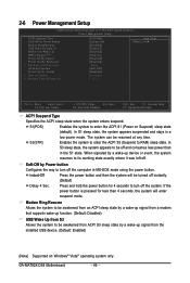
...)] [Instant-off instantly. GA-MA790X-DS4 Motherboard - 46 - In S1 sleep state, the system appears suspended and stays in the S1 state. Instant-Off Press the power button and then the system will enter suspend mode. Modem Ring Resume Allows the system to be awakened from an ACPI sleep state by a wake-up signal from a modem that supports wake-up function. (Default: Disabled) USB Wake Up from S3...
...)] [Instant-off instantly. GA-MA790X-DS4 Motherboard - 46 - In S1 sleep state, the system appears suspended and stays in the S1 state. Instant-Off Press the power button and then the system will enter suspend mode. Modem Ring Resume Allows the system to be awakened from an ACPI sleep state by a wake-up signal from a modem that supports wake-up function. (Default: Disabled) USB Wake Up from S3...

Manual
Page 50
... the threshold, BIOS will emit warning sound. PWM Sets PWM mode for a 3-pin CPU fan. System Smart FAN Control Enables or disables the system fan speed control function. Current System/CPU Temperature Displays current system/CPU temperature. Options are: Disabled (default), 60oC/140oF, 70oC/158oF, 80oC/ 176oF, 90oC/194oF. If disabled, CPU fan runs at different speed according to the system temperature. CPU Warning Temperature Sets the warning threshold for CPU temperature. This item is configurable only if CPU Smart FAN Control is not connected or fails. Current Voltage(V) Vcore...
... the threshold, BIOS will emit warning sound. PWM Sets PWM mode for a 3-pin CPU fan. System Smart FAN Control Enables or disables the system fan speed control function. Current System/CPU Temperature Displays current system/CPU temperature. Options are: Disabled (default), 60oC/140oF, 70oC/158oF, 80oC/ 176oF, 90oC/194oF. If disabled, CPU fan runs at different speed according to the system temperature. CPU Warning Temperature Sets the warning threshold for CPU temperature. This item is configurable only if CPU Smart FAN Control is not connected or fails. Current Voltage(V) Vcore...

Manual
Page 56
... key. GA-MA790X-DS4 Motherboard - 56 - Press or to return to the CMOS and exits the BIOS Setup program. This saves the changes to the BIOS Setup Main Menu. This exits the BIOS Setup without saving the changes made in BIOS Setup to the CMOS. 2-13 Save & Exit Setup CMOS Setup Utility-Copyright (C) 1984-2007 Award Software ` Standard CMOS Features Load Fail-Safe Defaults ` Advanced BIOS Features Load Optimized Defaults ` Integrated Peripherals Set Supervisor Password ` Power Management Setup Save to CMOS and EXIT (SYe/tNU)?seYr Password ` PnP/PCI Configurations...
... key. GA-MA790X-DS4 Motherboard - 56 - Press or to return to the CMOS and exits the BIOS Setup program. This saves the changes to the BIOS Setup Main Menu. This exits the BIOS Setup without saving the changes made in BIOS Setup to the CMOS. 2-13 Save & Exit Setup CMOS Setup Utility-Copyright (C) 1984-2007 Award Software ` Standard CMOS Features Load Fail-Safe Defaults ` Advanced BIOS Features Load Optimized Defaults ` Integrated Peripherals Set Supervisor Password ` Power Management Setup Save to CMOS and EXIT (SYe/tNU)?seYr Password ` PnP/PCI Configurations...

Manual
Page 73
... motherboard. Then connect the power connector from your power supply to the hard drive. (Note 1) Skip this step if you do not want to AHCI or RAID mode. - 73 - B. If you use two hard drives with identical model and capacity). Configure a RAID array in BIOS Setup. Make a floppy disk containing the SATA RAID/AHCI driver. (Note 2) E. Installing SATA hard drive(s) in your computer Attach one hard drive. • An empty formatted floppy disk. • Windows Vista/XP/2000 setup disk. • Motherboard driver disk. 5-1-1 Configuring the Onboard SATA Controller A. Chapter...
... motherboard. Then connect the power connector from your power supply to the hard drive. (Note 1) Skip this step if you do not want to AHCI or RAID mode. - 73 - B. If you use two hard drives with identical model and capacity). Configure a RAID array in BIOS Setup. Make a floppy disk containing the SATA RAID/AHCI driver. (Note 2) E. Installing SATA hard drive(s) in your computer Attach one hard drive. • An empty formatted floppy disk. • Windows Vista/XP/2000 setup disk. • Motherboard driver disk. 5-1-1 Configuring the Onboard SATA Controller A. Chapter...
Manual
Page 79
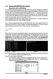
... formatted floppy disk. Step 1: Insert the prepared startup disk and motherboard driver disk in your optical drive folder, double click the MENU.exe file in Figure 2, to install Windows XP to your optical drive (example: D:\>). Press to your RAID/AHCI hard drives, select (3) SB600 SATA for the AMD SB600 SATA controller; For example, from the motherboard driver disk directly during the OS installation process. (Note 2) For users without a startup disk: Use an alternative system and insert the motherboard driver disk...
... formatted floppy disk. Step 1: Insert the prepared startup disk and motherboard driver disk in your optical drive folder, double click the MENU.exe file in Figure 2, to install Windows XP to your optical drive (example: D:\>). Press to your RAID/AHCI hard drives, select (3) SB600 SATA for the AMD SB600 SATA controller; For example, from the motherboard driver disk directly during the OS installation process. (Note 2) For users without a startup disk: Use an alternative system and insert the motherboard driver disk...

Manual
Page 80
... floppy disk containing the SATA RAID/AHCI driver and press (Figure 2). Currently, Setup will be a few moments of Windows XP and Vista installation. After pressing , there will load support for the following is an example of some files being loaded before you have a device support disk from a mass storage device manufacturer, or do not have chosen to install a 3rd party SCSI or RAID driver" (Figure 1). S=Specify Additional Device ENTER=Continue F3=Exit Figure 2 GA-MA790X-DS4 Motherboard...
... floppy disk containing the SATA RAID/AHCI driver and press (Figure 2). Currently, Setup will be a few moments of Windows XP and Vista installation. After pressing , there will load support for the following is an example of some files being loaded before you have a device support disk from a mass storage device manufacturer, or do not have chosen to install a 3rd party SCSI or RAID driver" (Figure 1). S=Specify Additional Device ENTER=Continue F3=Exit Figure 2 GA-MA790X-DS4 Motherboard...
Manual
Page 92
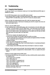
... the advanced options. Q: Why do the beeps emitted during the POST. A: The following Award BIOS beep code descriptions may help you identify possible computer problems. (For reference only.) 1 short: System boots successfully 2 short: CMOS setting error 1 long, 1 short: Memory or motherboard error 1 long, 2 short: Monitor or graphics card error 1 long, 3 short: Keyboard error 1 long, 9 short: BIOS ROM error Continuous long beeps: Graphics card not inserted properly Continuous short beeps: Power error GA-MA790X-DS4 Motherboard - 92 - Turn off your computer. 5. Replace the battery...
... the advanced options. Q: Why do the beeps emitted during the POST. A: The following Award BIOS beep code descriptions may help you identify possible computer problems. (For reference only.) 1 short: System boots successfully 2 short: CMOS setting error 1 long, 1 short: Memory or motherboard error 1 long, 2 short: Monitor or graphics card error 1 long, 3 short: Keyboard error 1 long, 9 short: BIOS ROM error Continuous long beeps: Graphics card not inserted properly Continuous short beeps: Power error GA-MA790X-DS4 Motherboard - 92 - Turn off your computer. 5. Replace the battery...


