Manual
Page 4
Table of Contents Box Contents ...6 OptionalItems ...6 GA-MA790X-DS4 Motherboard Layout 7 Block Diagram ...8 Chapter 1 Hardware Installation 9 1-1 Installation Precautions 9 1-2 Product Specifications 10 1-3 Installing the CPU and CPU Cooler 13 1-3-1 Installing the CPU 13 1-3-2 Installing the CPU Cooler 15 1-4 Installing the Memory 16 1-4-1 Dual Channel Memory Configuration 16 1-4-2 Installing a Memory 17 1-5 Installing an Expansion Card 18 1-6 Back Panel Connectors 20...
Table of Contents Box Contents ...6 OptionalItems ...6 GA-MA790X-DS4 Motherboard Layout 7 Block Diagram ...8 Chapter 1 Hardware Installation 9 1-1 Installation Precautions 9 1-2 Product Specifications 10 1-3 Installing the CPU and CPU Cooler 13 1-3-1 Installing the CPU 13 1-3-2 Installing the CPU Cooler 15 1-4 Installing the Memory 16 1-4-1 Dual Channel Memory Configuration 16 1-4-2 Installing a Memory 17 1-5 Installing an Expansion Card 18 1-6 Back Panel Connectors 20...

Manual
Page 8
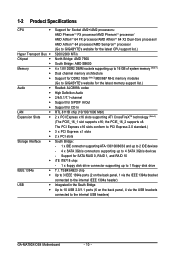
Block Diagram 1 PCIe x16 2 PCIe x8 PCIe CLK (100 MHz) or AMD Socket AM2 CPU CPU CLK+/-(200 MHz) DDR2 1066/800/667 MHz DIMM Dual Channel Memory Hyper Transport 3.0 Switch PCI Express x 16 Bus PCI Express Bus x1 x1 x1 x1 PCIe CLK (100 MHz) RTL8111B 3 PCI Express x1 RJ45 LAN PCI Bus TSB43AB23 AMD 790X AMD SB600 Dual BIOS 4 SATA 3Gb/s ATA-133/100/66/33 IDE Channel 10 USB Ports CODEC LPC BUS IT8718 Floppy LPT Port COM Port 3 IEEE 1394a PS/2 KB/Mouse Surround Speaker Out Center/Subwoofer Speaker Out Side Speaker Out MIC Line-Out Line-In SPDIF In SPDIF Out 2 PCI - 8 -
Block Diagram 1 PCIe x16 2 PCIe x8 PCIe CLK (100 MHz) or AMD Socket AM2 CPU CPU CLK+/-(200 MHz) DDR2 1066/800/667 MHz DIMM Dual Channel Memory Hyper Transport 3.0 Switch PCI Express x 16 Bus PCI Express Bus x1 x1 x1 x1 PCIe CLK (100 MHz) RTL8111B 3 PCI Express x1 RJ45 LAN PCI Bus TSB43AB23 AMD 790X AMD SB600 Dual BIOS 4 SATA 3Gb/s ATA-133/100/66/33 IDE Channel 10 USB Ports CODEC LPC BUS IT8718 Floppy LPT Port COM Port 3 IEEE 1394a PS/2 KB/Mouse Surround Speaker Out Center/Subwoofer Speaker Out Side Speaker Out MIC Line-Out Line-In SPDIF In SPDIF Out 2 PCI - 8 -

Manual
Page 9
.... • Prior to installing the motherboard, please have a problem related to wear an electrostatic discharge (ESD) wrist strap when handling electronic components such as a motherboard, CPU or memory. If you are connected tightly and securely. • When handling the motherboard, avoid touching any installation steps or have it on top of...
.... • Prior to installing the motherboard, please have a problem related to wear an electrostatic discharge (ESD) wrist strap when handling electronic components such as a motherboard, CPU or memory. If you are connected tightly and securely. • When handling the motherboard, avoid touching any installation steps or have it on top of...
Manual
Page 10
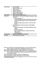
... processor/ AMD AthlonTM 64 FX processor/AMD AthlonTM 64 X2 Dual-Core processor/ AMD AthlonTM 64 processor/AMD SempronTM processor (Go to GIGABYTE's website for the latest CPU support list.) 5200/2000 MT/s North Bridge: AMD 790X South Bridge: AMD SB600 4 x 1.8V DDR2 DIMM sockets supporting up... Integrated in the South Bridge Up to 10 USB 2.0/1.1 ports (6 on the back panel, 4 via the USB brackets connected to the internal USB headers) GA-MA790X-DS4 Motherboard - 10 - Support for CD In RTL 8111B chip (10/100/1000 Mbit) 2 x PCI Express x16 slots supporting ATI CrossFireXTM technology (Note 3) ...
... processor/ AMD AthlonTM 64 FX processor/AMD AthlonTM 64 X2 Dual-Core processor/ AMD AthlonTM 64 processor/AMD SempronTM processor (Go to GIGABYTE's website for the latest CPU support list.) 5200/2000 MT/s North Bridge: AMD 790X South Bridge: AMD SB600 4 x 1.8V DDR2 DIMM sockets supporting up... Integrated in the South Bridge Up to 10 USB 2.0/1.1 ports (6 on the back panel, 4 via the USB brackets connected to the internal USB headers) GA-MA790X-DS4 Motherboard - 10 - Support for CD In RTL 8111B chip (10/100/1000 Mbit) 2 x PCI Express x16 slots supporting ATI CrossFireXTM technology (Note 3) ...

Manual
Page 11
...138; 1 x 4-pin PCIe 12V power connector Š 1 x floppy disk drive connector Š 1 x IDE connector Š 4 x SATA 3Gb/s connectors Š 1 x CPU fan header Š 2 x system fan headers Š 1 x power fan header Š 1 x North Bridge fan header Š 1 x front panel header Š 1 ... iTE IT8718 chip Hardware Monitor Š System voltage detection Š CPU/System temperature detection Š CPU/System/Power fan speed detection Š CPU overheating warning Š CPU/System/Power fan fail warning Š CPU/System fan speed control BIOS Š 2 x 4 Mbit flash ...
...138; 1 x 4-pin PCIe 12V power connector Š 1 x floppy disk drive connector Š 1 x IDE connector Š 4 x SATA 3Gb/s connectors Š 1 x CPU fan header Š 2 x system fan headers Š 1 x power fan header Š 1 x North Bridge fan header Š 1 x front panel header Š 1 ... iTE IT8718 chip Hardware Monitor Š System voltage detection Š CPU/System temperature detection Š CPU/System/Power fan speed detection Š CPU overheating warning Š CPU/System/Power fan fail warning Š CPU/System fan speed control BIOS Š 2 x 4 Mbit flash ...
Manual
Page 12
...with 0.025V increment Š Frequency adjustments in BIOS Setup (CPU/DDR2/North Bridge/South Bridge) allow you to: - Adjust HT Link frequency - Increase North Bridge voltage by 0.025V to 0.3750V with 0.025V increment - GA-MA790X-DS4 Motherboard - 12 - If you to: - Increase South... Bridge voltage by motherboard model. (Note 5) The adjustable CPU voltage range depends on the CPU being used. (Note 3) When the CrossFireXTM technology is enabled, the...
...with 0.025V increment Š Frequency adjustments in BIOS Setup (CPU/DDR2/North Bridge/South Bridge) allow you to: - Adjust HT Link frequency - Increase North Bridge voltage by 0.025V to 0.3750V with 0.025V increment - GA-MA790X-DS4 Motherboard - 12 - If you to: - Increase South... Bridge voltage by motherboard model. (Note 5) The adjustable CPU voltage range depends on the CPU being used. (Note 3) When the CrossFireXTM technology is enabled, the...

Manual
Page 13
... the motherboard supports the CPU. (Go to GIGABYTE's website for the peripherals. A Small Triangle Mark Denotes Pin One of the CPU. It is not installed, otherwise overheating and damage of the CPU socket and the CPU. Locate the pin one of the Socket AM2 CPU Socket A Small Triangle Marking Denotes CPU Pin One AM2 CPU - 13 - If you...
... the motherboard supports the CPU. (Go to GIGABYTE's website for the peripherals. A Small Triangle Mark Denotes Pin One of the CPU. It is not installed, otherwise overheating and damage of the CPU socket and the CPU. Locate the pin one of the Socket AM2 CPU Socket A Small Triangle Marking Denotes CPU Pin One AM2 CPU - 13 - If you...
Manual
Page 14
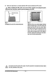
.... Step 2: Align the CPU pin one finger down on the CPU socket and gently insert the CPU into the fully locked position. GA-MA790X-DS4 Motherboard - 14 - CPU Socket Locking Lever Step 1: Completely lift up the CPU socket locking lever. Adjust the CPU orientation if this occurs. Make sure that the CPU pins fit perfectly into the CPU socket. B. Follow the...
.... Step 2: Align the CPU pin one finger down on the CPU socket and gently insert the CPU into the fully locked position. GA-MA790X-DS4 Motherboard - 14 - CPU Socket Locking Lever Step 1: Completely lift up the CPU socket locking lever. Adjust the CPU orientation if this occurs. Make sure that the CPU pins fit perfectly into the CPU socket. B. Follow the...
Manual
Page 15
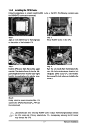
... the mounting lug on the CPU. Use extreme care when removing the CPU cooler because the thermal grease/tape between the CPU cooler and CPU may damage the CPU. - 15 - Hardware Installation 1-3-2 Installing the CPU Cooler Follow the steps below to correctly install the CPU cooler on the CPU. (The following procedure uses the GIGABYTE cooler as the picture...
... the mounting lug on the CPU. Use extreme care when removing the CPU cooler because the thermal grease/tape between the CPU cooler and CPU may damage the CPU. - 15 - Hardware Installation 1-3-2 Installing the CPU Cooler Follow the steps below to correctly install the CPU cooler on the CPU. (The following procedure uses the GIGABYTE cooler as the picture...
Manual
Page 16
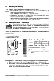
...brand, speed, and chips be used and installed in Dual Channel mode. 1. If you install them in the DDRII_1 and DDRII_2 sockets. GA-MA790X-DS4 Motherboard - 16 - 1-4 Installing the Memory Read the following guidelines before you begin to be installed, it is installed. 2. After ...the specifications and capacity of the same capacity, brand, speed, and chips be used . (Go to GIGABYTE's website for optimum performance. DDRII_1 DDRII_2 DDRII_3 DDRII_4 Due to CPU limitation, read the following : Channel 0: DDRII_1, DDRII_3 Channel 1: DDRII_2, DDRII_4 Dual Channel Memory Configurations ...
...brand, speed, and chips be used and installed in Dual Channel mode. 1. If you install them in the DDRII_1 and DDRII_2 sockets. GA-MA790X-DS4 Motherboard - 16 - 1-4 Installing the Memory Read the following guidelines before you begin to be installed, it is installed. 2. After ...the specifications and capacity of the same capacity, brand, speed, and chips be used . (Go to GIGABYTE's website for optimum performance. DDRII_1 DDRII_2 DDRII_3 DDRII_4 Due to CPU limitation, read the following : Channel 0: DDRII_1, DDRII_3 Channel 1: DDRII_2, DDRII_4 Dual Channel Memory Configurations ...
Manual
Page 23
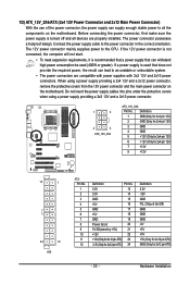
... on the motherboard. When using a power supply providing a 2x2 12V and a 2x10 power connector. 1 5 4 8 ATX_12V_2X4 ATX_12V_2X4: Pin No. Connect the power supply cable to the CPU. Do not insert the power supply cables into pins under the protective covers when using a power supply providing a 2x4 12V and a 2x12 power connector, remove...
... on the motherboard. When using a power supply providing a 2x2 12V and a 2x10 power connector. 1 5 4 8 ATX_12V_2X4 ATX_12V_2X4: Pin No. Connect the power supply cable to the CPU. Do not insert the power supply cables into pins under the protective covers when using a power supply providing a 2x4 12V and a 2x12 power connector, remove...
Manual
Page 24
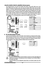
...Definition 1 GND 2 +12V 3 Sense 6) NB_FAN (North Bridge Fan Header) Connect the North Bridge fan cable to the CPU/North Bridge or the system may result in damage to this header. Most fans are designed with color-coded power connector wires.... and requires a +12V voltage. A red power connector wire indicates a positive connection and requires a +12V voltage. GA-MA790X-DS4 Motherboard - 24 - 3/4/5) CPU_FAN/SYS_FAN1/SYS_FAN2/PWR_FAN (Fan Headers) The motherboard has a 4-pin CPU fan header (CPU_FAN), a 4-pin (SYS_FAN1) and a 3-pin (SYS_FAN2) system fan header, and a 3-pin...
...Definition 1 GND 2 +12V 3 Sense 6) NB_FAN (North Bridge Fan Header) Connect the North Bridge fan cable to the CPU/North Bridge or the system may result in damage to this header. Most fans are designed with color-coded power connector wires.... and requires a +12V voltage. A red power connector wire indicates a positive connection and requires a +12V voltage. GA-MA790X-DS4 Motherboard - 24 - 3/4/5) CPU_FAN/SYS_FAN1/SYS_FAN2/PWR_FAN (Fan Headers) The motherboard has a 4-pin CPU fan header (CPU_FAN), a 4-pin (SYS_FAN1) and a 3-pin (SYS_FAN2) system fan header, and a 3-pin...

Manual
Page 38
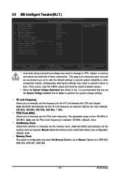
... menu to configure the system's PCI & PnP resources. „ PC Health Status Use this menu to see information about autodetected system/CPU temperature, system voltage and fan speed, etc. „ MB Intelligent Tweaker(M.I.T.) Use this menu to configure the clock, frequency and voltages...132; Set Supervisor Password Change, set , or disable password. First enter the profile name (to erase the default profile name, use this task.) GA-MA790X-DS4 Motherboard - 38 - Pressing to 8 profiles (Profile 1-8) and name each profile. First select the profile you wish to load, then press to complete...
... menu to configure the system's PCI & PnP resources. „ PC Health Status Use this menu to see information about autodetected system/CPU temperature, system voltage and fan speed, etc. „ MB Intelligent Tweaker(M.I.T.) Use this menu to configure the clock, frequency and voltages...132; Set Supervisor Password Change, set , or disable password. First enter the profile name (to erase the default profile name, use this task.) GA-MA790X-DS4 Motherboard - 38 - Pressing to 8 profiles (Profile 1-8) and name each profile. First select the profile you wish to load, then press to complete...

Manual
Page 41
... computer system can function as multiple virtual systems. (Default: Disabled) AMD K8 Cool&Quiet control Auto Lets the AMD Cool'n'Quiet driver dynamically adjust the CPU clock and VIA to accept. Hard Disk Boot Priority Specifies the sequence of loading the operating system from the available devices. BIOS Setup First/Second...
... computer system can function as multiple virtual systems. (Default: Disabled) AMD K8 Cool&Quiet control Auto Lets the AMD Cool'n'Quiet driver dynamically adjust the CPU clock and VIA to accept. Hard Disk Boot Priority Specifies the sequence of loading the operating system from the available devices. BIOS Setup First/Second...

Manual
Page 49
...Status Case Opened Vcore DDR2 1.8V +3.3V +12V Current System Temperature Current CPU Temperature Current CPU FAN Speed Current SYSTEM FAN1 Speed Current SYSTEM FAN2 Speed Current POWER FAN Speed CPU Warning Temperature CPU FAN Fail Warning SYSTEM FAN1 Fail Warning SYSTEM FAN2 Fail Warning POWER FAN ...Fail Warning CPU Smart FAN Control CPU Smart FAN Mode [Disabled] No 1.376V 1.904V 3.328V 11.985V 30oC 47oC 3375...
...Status Case Opened Vcore DDR2 1.8V +3.3V +12V Current System Temperature Current CPU Temperature Current CPU FAN Speed Current SYSTEM FAN1 Speed Current SYSTEM FAN2 Speed Current POWER FAN Speed CPU Warning Temperature CPU FAN Fail Warning SYSTEM FAN1 Fail Warning SYSTEM FAN2 Fail Warning POWER FAN ...Fail Warning CPU Smart FAN Control CPU Smart FAN Mode [Disabled] No 1.376V 1.904V 3.328V 11.985V 30oC 47oC 3375...

Manual
Page 50
... FAN Fail Warning Allows the system to the CPU temperature. Enabled allows the CPU fan to run at different speed according to emit warning sound if the CPU/system/power fan is set to the system temperature. If disabled, CPU fan runs at full speed. (Default: Enabled) GA-MA790X-DS4 Motherboard - 50 - If disabled, system fan runs...
... FAN Fail Warning Allows the system to the CPU temperature. Enabled allows the CPU fan to run at different speed according to emit warning sound if the CPU/system/power fan is set to the system temperature. If disabled, CPU fan runs at full speed. (Default: Enabled) GA-MA790X-DS4 Motherboard - 50 - If disabled, system fan runs...
Manual
Page 51
...system instability or other unexpected results. (Inadequately altering the settings may result in damage to CPU, chipset, or memory and reduce the useful life of these components. The adjustable range is for the HT Link between ...Tweaker(M.I.T.) HT Link Frequency PCIE Clock (MHz) Set Memory Clock x Memory Clock ` DRAM Configuration CPU Clock Ratio CPU Host Clock Control x CPU Frequency (MHz) ******** System Voltage Optimized System Voltage Control x CPU Voltage Control Normal CPU Vcore x DDR2 Voltage Control x NorthBridge Volt Control x SouthBridge Volt Control ******** [Auto] [...
...system instability or other unexpected results. (Inadequately altering the settings may result in damage to CPU, chipset, or memory and reduce the useful life of these components. The adjustable range is for the HT Link between ...Tweaker(M.I.T.) HT Link Frequency PCIE Clock (MHz) Set Memory Clock x Memory Clock ` DRAM Configuration CPU Clock Ratio CPU Host Clock Control x CPU Frequency (MHz) ******** System Voltage Optimized System Voltage Control x CPU Voltage Control Normal CPU Vcore x DDR2 Voltage Control x NorthBridge Volt Control x SouthBridge Volt Control ******** [Auto] [...

Manual
Page 53
... the system voltages as required. (Default) +0.025V ~ +0.375V Increases South Bridge voltage by 0.025V to 0.375V at 0.025V increment. - 53 - CPU Clock Ratio Allows you to alter the clock ratio for automated system reboot, or clear the CMOS values to reset the board to default values.... BIOS Setup Auto (default) allows BIOS to 500 MHz. The adjustable range is highly recommended that the CPU frequency be configurable. Normal CPU Vcore Displays the normal operating voltage of your system fails to boot after overclocking, please wait for 20 seconds to allow ...
... the system voltages as required. (Default) +0.025V ~ +0.375V Increases South Bridge voltage by 0.025V to 0.375V at 0.025V increment. - 53 - CPU Clock Ratio Allows you to alter the clock ratio for automated system reboot, or clear the CMOS values to reset the board to default values.... BIOS Setup Auto (default) allows BIOS to 500 MHz. The adjustable range is highly recommended that the CPU frequency be configurable. Normal CPU Vcore Displays the normal operating voltage of your system fails to boot after overclocking, please wait for 20 seconds to allow ...

Manual
Page 71
... HEALTH setting page Confirmation/execution button Toggles among Easy Mode, Advanced Mode, and Graphics Mode Displays the CPU frequency Shows the supported function(s) Go to GIGABYTE website to update EasyTune 5 Pro Opens EasyTune 5 Pro help file Quits or minimizes the EasyTune 5... Pro interface Performance Enhancement Incorrectly doing overclock/overvoltage may provide optimizations for CPU and memory, enhancing the performance of these components....
... HEALTH setting page Confirmation/execution button Toggles among Easy Mode, Advanced Mode, and Graphics Mode Displays the CPU frequency Shows the supported function(s) Go to GIGABYTE website to update EasyTune 5 Pro Opens EasyTune 5 Pro help file Quits or minimizes the EasyTune 5... Pro interface Performance Enhancement Incorrectly doing overclock/overvoltage may provide optimizations for CPU and memory, enhancing the performance of these components....

Manual
Page 93
... card. The problem is verified and solved. The problem is verified and solved. Select "Save & Exit Setup" to solve the problem. No Check if the CPU cooler is verified and solved. Yes Isolate the short circuit. START Turn off the power. Make sure the motherboard does not short-circuit with the... chassis or other metal objects. Is the power connector of the CPU cooler connected to the motherboard. Connect the ATX main power cable and the 12V power cable. The problem is attached to the...
... card. The problem is verified and solved. The problem is verified and solved. Select "Save & Exit Setup" to solve the problem. No Check if the CPU cooler is verified and solved. Yes Isolate the short circuit. START Turn off the power. Make sure the motherboard does not short-circuit with the... chassis or other metal objects. Is the power connector of the CPU cooler connected to the motherboard. Connect the ATX main power cable and the 12V power cable. The problem is attached to the...


