Manual
Page 3
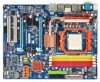
... is the property of the motherboard is 1.0. The logo is designated by GIGABYTE without GIGABYTE's prior written permission. Disclaimer Information in this manual may be made by GIGA-BYTE TECHNOLOGY CO., LTD as the exclu- Documentation Classifications In order to assist in ... product information, carefully read the User's Manual. „ For instructions on how to use GIGABYTE's unique features, read or download the information on/from the Support\Motherboard\Technology Guide page on your motherboard revision before updating motherboard BIOS, drivers, or when looking for technical...
... is the property of the motherboard is 1.0. The logo is designated by GIGABYTE without GIGABYTE's prior written permission. Disclaimer Information in this manual may be made by GIGA-BYTE TECHNOLOGY CO., LTD as the exclu- Documentation Classifications In order to assist in ... product information, carefully read the User's Manual. „ For instructions on how to use GIGABYTE's unique features, read or download the information on/from the Support\Motherboard\Technology Guide page on your motherboard revision before updating motherboard BIOS, drivers, or when looking for technical...
Manual
Page 10
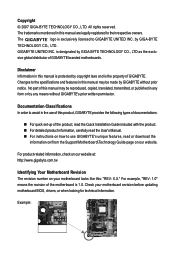
...GIGABYTE SATA2 chip: - 2 x SATA 3Gb/s connectors (GSATAII_1, GSATAII_2) supporting up to 2 SATA 3Gb/s devices - TSB43AB23 chip Up to 3 IEEE 1394a ports (2 on the back panel supporting up to 2 SATA 3Gb/s devices - 2 x eSATA 3Gb/s ports on the back panel, 1 via the IEEE 1394a bracket connected to the internal IEEE 1394a header) GA-MA790FX-DS5...S/PDIF In/Out Support for CD In Realtek 8111B chip (10/100/1000 Mbit) 2 x PCI Express x16 slots supporting ATI CrossFireXTM technology (The PCI Express x16 slots conform to PCI Express 2.0 standard.) 3 x PCI Express x1 slots 2 x PCI slots South Bridge: ...
...GIGABYTE SATA2 chip: - 2 x SATA 3Gb/s connectors (GSATAII_1, GSATAII_2) supporting up to 2 SATA 3Gb/s devices - TSB43AB23 chip Up to 3 IEEE 1394a ports (2 on the back panel supporting up to 2 SATA 3Gb/s devices - 2 x eSATA 3Gb/s ports on the back panel, 1 via the IEEE 1394a bracket connected to the internal IEEE 1394a header) GA-MA790FX-DS5...S/PDIF In/Out Support for CD In Realtek 8111B chip (10/100/1000 Mbit) 2 x PCI Express x16 slots supporting ATI CrossFireXTM technology (The PCI Express x16 slots conform to PCI Express 2.0 standard.) 3 x PCI Express x1 slots 2 x PCI slots South Bridge: ...
Manual
Page 16
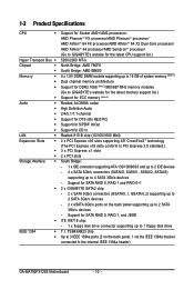
...recommended that memory of the same capacity, brand, speed, and chips be used and installed in Dual Channel mode. 1. GA-MA790FX-DS5 Motherboard - 16 - It is recommended that the motherboard supports the memory. A memory module can be installed, it ...detect the specifications and capacity of the same capacity, brand, speed, and chips be used . (Go to GIGABYTE's website for optimum performance. If you install them in only one DDR2 memory module is installed, the BIOS will...Configuration This motherboard provides four DDR2 memory sockets and supports Dual Channel Technology.
...recommended that memory of the same capacity, brand, speed, and chips be used and installed in Dual Channel mode. 1. GA-MA790FX-DS5 Motherboard - 16 - It is recommended that the motherboard supports the memory. A memory module can be installed, it ...detect the specifications and capacity of the same capacity, brand, speed, and chips be used . (Go to GIGABYTE's website for optimum performance. If you install them in only one DDR2 memory module is installed, the BIOS will...Configuration This motherboard provides four DDR2 memory sockets and supports Dual Channel Technology.
Manual
Page 43
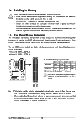
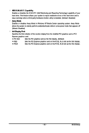
.... PEG1 Sets the PCI Express graphics card on the PCIE_16_A slot as the first display. - 43 - Capability Enables or disables the S.M.A.R.T. (Self Monitoring and Reporting Technology) capability of the monitor display from the installed PCI graphics card or PCI Express graphics card. HDD S.M.A.R.T. PCI Slot Sets the PCI graphics card as...
.... PEG1 Sets the PCI Express graphics card on the PCIE_16_A slot as the first display. - 43 - Capability Enables or disables the S.M.A.R.T. (Self Monitoring and Reporting Technology) capability of the monitor display from the installed PCI graphics card or PCI Express graphics card. HDD S.M.A.R.T. PCI Slot Sets the PCI graphics card as...

Manual
Page 79
RAID BIOS Version 2.5.1540.36 (c) 2006 ATI Technology, Inc. Press to enter the Delete LD window. To delete an array, press to enter FastBuild (tm) Utility... To view controller settings, press to enter ... the ATI BIOS RAID Setup utility. (Figure 3). To create an array, press to enter the ATI RAID BIOS setup utility. C. FastBuild (tm) Utility (c) 2006 ATI Technology, Inc. [ Main Menu] ] View Drive Assignments 1 ] Define LD 2 ] Delete LD 3 ] Controller Configuration 4 ] Press 1..4 to enter the View Drive Assignments window. To view the disk drives...
RAID BIOS Version 2.5.1540.36 (c) 2006 ATI Technology, Inc. Press to enter the Delete LD window. To delete an array, press to enter FastBuild (tm) Utility... To view controller settings, press to enter ... the ATI BIOS RAID Setup utility. (Figure 3). To create an array, press to enter the ATI RAID BIOS setup utility. C. FastBuild (tm) Utility (c) 2006 ATI Technology, Inc. [ Main Menu] ] View Drive Assignments 1 ] Define LD 2 ] Delete LD 3 ] Controller Configuration 4 ] Press 1..4 to enter the View Drive Assignments window. To view the disk drives...
Manual
Page 80
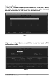
...Gigabyte Boundary: 64 KB ON Fast Init: OFF Cache Mode: WriteThru [ Drives Assignments] ] Channel:ID Drive Model 1:Mas WDC WD800JD-22LSA0 2:Mas WDC WD800JD-22LSA0 Capacity (MB) 80026 80026 Assignment N N [K] Up [L] Down [ Keys Available] ] [ESC] Exit [Space] Change Option Figure 5 [Ctrl-Y] Save GA-MA790FX-DS5... Motherboard - 80 - Create Arrays Manually To create a new array, press to the AMD SB600 controller. FastBuild (tm) Utility (c) 2006 ATI Technology, Inc. The Define LD selection from the Main Menu ...
...Gigabyte Boundary: 64 KB ON Fast Init: OFF Cache Mode: WriteThru [ Drives Assignments] ] Channel:ID Drive Model 1:Mas WDC WD800JD-22LSA0 2:Mas WDC WD800JD-22LSA0 Capacity (MB) 80026 80026 Assignment N N [K] Up [L] Down [ Keys Available] ] [ESC] Exit [Space] Change Option Figure 5 [Ctrl-Y] Save GA-MA790FX-DS5... Motherboard - 80 - Create Arrays Manually To create a new array, press to the AMD SB600 controller. FastBuild (tm) Utility (c) 2006 ATI Technology, Inc. The Define LD selection from the Main Menu ...

Manual
Page 81
..., press the Spacebar to use maximum capacity... Press the Spacebar or to change the Assignment option to its maximum capacity. 7. FastBuild (tm) Utility (c) 2006 ATI Technology, Inc. The window below will show the number of the RAID array or press other key to select RAID 0. 2. Press + to set the array to...
..., press the Spacebar to use maximum capacity... Press the Spacebar or to change the Assignment option to its maximum capacity. 7. FastBuild (tm) Utility (c) 2006 ATI Technology, Inc. The window below will show the number of the RAID array or press other key to select RAID 0. 2. Press + to set the array to...

Manual
Page 82
Then highlight the array you wish to this array? FastBuild (tm) Utility (c) 2006 ATI Technology, Inc. Figure 8 GA-MA790FX-DS5 Motherboard - 82 - Deleting an existing disk array could result in case you wish to enter the Delete LD Menu. To delete an array, press in ...
Then highlight the array you wish to this array? FastBuild (tm) Utility (c) 2006 ATI Technology, Inc. Figure 8 GA-MA790FX-DS5 Motherboard - 82 - Deleting an existing disk array could result in case you wish to enter the Delete LD Menu. To delete an array, press in ...
Manual
Page 85
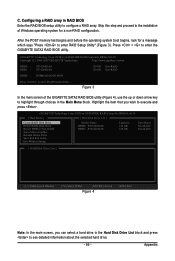
... a hard drive in RAID BIOS Enter the RAID BIOS setup utility to see detailed information about the selected hard drive. - 85 - GIGABYTE Technology Corp. C. Configuring a RAID array in the Hard Disk Drive List block and press to configure a RAID array. PCIE-to-SATAII/IDE...SATAII/IDE RAID Controller BIOSv1.06.59 Copyright (C) 2006-2007 GIGABYTE Technology. PCIE-to the installation of the GIGABYTE SATA2 RAID BIOS utility (Figure 4), use the up or down arrow key to execute and press . GIGABYTE Technology Corp. After the POST memory test begins and before the operating...
... a hard drive in RAID BIOS Enter the RAID BIOS setup utility to see detailed information about the selected hard drive. - 85 - GIGABYTE Technology Corp. C. Configuring a RAID array in the Hard Disk Drive List block and press to configure a RAID array. PCIE-to-SATAII/IDE...SATAII/IDE RAID Controller BIOSv1.06.59 Copyright (C) 2006-2007 GIGABYTE Technology. PCIE-to the installation of the GIGABYTE SATA2 RAID BIOS utility (Figure 4), use the up or down arrow key to execute and press . GIGABYTE Technology Corp. After the POST memory test begins and before the operating...
Manual
Page 86
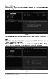
...Stripe), RAID 1 (Mirror), or JBOD (Figure 6). Then the Create New RAID screen appears (Figure 5). GIGABYTE Technology Corp. Select RAID Mode: Under the Level item, use up or down arrow key to -SATAII/IDE ...[ESC]-Abort The Create New RAID block displays all the items that need to move onto the next step. GIGABYTE Technology Corp. Data striped for performance Data mirrored for redundancy Data concatenated for creating an array (Figure 6). Steps: ... set for huge temporarily disk required [KL]-Switch RAID Level GA-MA790FX-DS5 Motherboard [ENTER]-Next Figure 6 - 86 - [ESC]-Abort
...Stripe), RAID 1 (Mirror), or JBOD (Figure 6). Then the Create New RAID screen appears (Figure 5). GIGABYTE Technology Corp. Select RAID Mode: Under the Level item, use up or down arrow key to -SATAII/IDE ...[ESC]-Abort The Create New RAID block displays all the items that need to move onto the next step. GIGABYTE Technology Corp. Data striped for performance Data mirrored for redundancy Data concatenated for creating an array (Figure 6). Steps: ... set for huge temporarily disk required [KL]-Switch RAID Level GA-MA790FX-DS5 Motherboard [ENTER]-Next Figure 6 - 86 - [ESC]-Abort

Manual
Page 87
...After a RAID mode is selected, RAID BIOS automatically assigns the two hard drives installed as the RAID drives. 4. Press . Press . GIGABYTE Technology Corp. Appendix Set Array Size: Under the Size item, enter the size of the items above are typical values: RAID 0-128KB [...Switch RAID Block Size [ENTER]-Next Figure 7 [ESC]-Abort 5. 3. The following are configured, the selection bar automatically jumps to 128 KB. GIGABYTE Technology Corp. When prompted to confirm your selection (Figure 8), press to confirm or to -SATAII/IDE RAID Controller BIOSv1.06.59 [ Create New RAID...
...After a RAID mode is selected, RAID BIOS automatically assigns the two hard drives installed as the RAID drives. 4. Press . Press . GIGABYTE Technology Corp. Appendix Set Array Size: Under the Size item, enter the size of the items above are typical values: RAID 0-128KB [...Switch RAID Block Size [ENTER]-Next Figure 7 [ESC]-Abort 5. 3. The following are configured, the selection bar automatically jumps to 128 KB. GIGABYTE Technology Corp. When prompted to confirm your selection (Figure 8), press to confirm or to -SATAII/IDE RAID Controller BIOSv1.06.59 [ Create New RAID...
Manual
Page 88
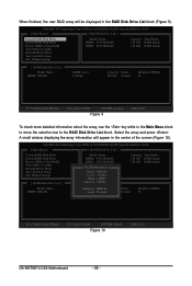
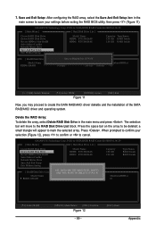
...RAID Disk Drive List block. A small window displaying the array information will be displayed in the center of the screen (Figure 10). GIGABYTE Technology Corp. GIGABYTE Technology Corp. PCIE-to-SATAII/IDE RAID Controller BIOSv1.06.59 [ Main Menu ] [ Hard Disk Drive List ] Create RAID Disk Drive...0-Stripe Status: Normal 240 GB Normal Members(HDDx) 01 [IJTAB]-Switch Window [KL]-Select RAID [ENTER]-Detail Figure 10 [ESC]-Exit GA-MA790FX-DS5 Motherboard - 88 - Select the array and press . When finished, the new RAID array will appear in the RAID Disk Drive List block (...
...RAID Disk Drive List block. A small window displaying the array information will be displayed in the center of the screen (Figure 10). GIGABYTE Technology Corp. GIGABYTE Technology Corp. PCIE-to-SATAII/IDE RAID Controller BIOSv1.06.59 [ Main Menu ] [ Hard Disk Drive List ] Create RAID Disk Drive...0-Stripe Status: Normal 240 GB Normal Members(HDDx) 01 [IJTAB]-Switch Window [KL]-Select RAID [ENTER]-Detail Figure 10 [ESC]-Exit GA-MA790FX-DS5 Motherboard - 88 - Select the array and press . When finished, the new RAID array will appear in the RAID Disk Drive List block (...
Manual
Page 89
7. GIGABYTE Technology Corp. PCIE-to-SATAII/IDE RAID Controller BIOSv1.06.59 [ Main Menu ] [ Hard Disk Drive List ] Create RAID Disk Drive Delete RAID Disk Drive Revert ... ` RDD0: GRAID ALL DATA ON THE RAID WILL LOST!! When prompted to confirm your settings before exiting the RAID BIOS utility, then press (Figure 11). GIGABYTE Technology Corp.
7. GIGABYTE Technology Corp. PCIE-to-SATAII/IDE RAID Controller BIOSv1.06.59 [ Main Menu ] [ Hard Disk Drive List ] Create RAID Disk Drive Delete RAID Disk Drive Revert ... ` RDD0: GRAID ALL DATA ON THE RAID WILL LOST!! When prompted to confirm your settings before exiting the RAID BIOS utility, then press (Figure 11). GIGABYTE Technology Corp.
Manual
Page 116
... : http://www.gigabyte.ru Latvia GIGA-BYTE Latvia WEB address : http://www.gigabyte.lv Poland Office of the website. WEB address : http://www.giga-byte.co.uk The Netherlands GIGA-BYTE TECHNOLOGY B.V. in Romania WEB address : http://www.gigabyte.com.ro Serbia & Montenegro Representative Office Of GIGA-BYTE Technology Co., Ltd. Germany G.B.T. CO., LTD. GA-MA790FX-DS5 Motherboard...
... : http://www.gigabyte.ru Latvia GIGA-BYTE Latvia WEB address : http://www.gigabyte.lv Poland Office of the website. WEB address : http://www.giga-byte.co.uk The Netherlands GIGA-BYTE TECHNOLOGY B.V. in Romania WEB address : http://www.gigabyte.com.ro Serbia & Montenegro Representative Office Of GIGA-BYTE Technology Co., Ltd. Germany G.B.T. CO., LTD. GA-MA790FX-DS5 Motherboard...
