Manual
Page 4
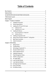
...GA-MA785GPM-UD2H/GA-MA78GM-UD2H(US2H 7 Motherboard Layout...7 Block Diagram...8 Chapter 1 Hardware Installation 9 1-1 Installation Precautions 9 1-2 Product Specifications 10 1-3 Installing the CPU and CPU Cooler 13 1-3-1 Installing the CPU 13 1-3-2 Installing the CPU Cooler 15 1-4 Installing the Memory 16 1-4-1 Dual Channel Memory Configuration 16 1-4-2 Installing a Memory 17 1-5 Installing an Expansion Card 18 1-6 Setup... 44 2-5 Advanced BIOS Features 46 2-6 Integrated Peripherals 49 2-7 Power Management Setup 52 2-8 PnP/PCI Configurations 54 2-9 PC Health Status 55 2-10 Load...
...GA-MA785GPM-UD2H/GA-MA78GM-UD2H(US2H 7 Motherboard Layout...7 Block Diagram...8 Chapter 1 Hardware Installation 9 1-1 Installation Precautions 9 1-2 Product Specifications 10 1-3 Installing the CPU and CPU Cooler 13 1-3-1 Installing the CPU 13 1-3-2 Installing the CPU Cooler 15 1-4 Installing the Memory 16 1-4-1 Dual Channel Memory Configuration 16 1-4-2 Installing a Memory 17 1-5 Installing an Expansion Card 18 1-6 Setup... 44 2-5 Advanced BIOS Features 46 2-6 Integrated Peripherals 49 2-7 Power Management Setup 52 2-8 PnP/PCI Configurations 54 2-9 PC Health Status 55 2-10 Load...
Manual
Page 18
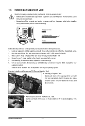
... metal contacts on your expansion card in the slot and does not rock. • Removing the Card from the slot. If necessary, go to BIOS Setup to correctly install your computer. Make sure the card is fully inserted into the slot. 4. PCI Express x1 Slot PCI Express x16 Slot PCI Slot...
... metal contacts on your expansion card in the slot and does not rock. • Removing the Card from the slot. If necessary, go to BIOS Setup to correctly install your computer. Make sure the card is fully inserted into the slot. 4. PCI Express x1 Slot PCI Express x16 Slot PCI Slot...
Manual
Page 19
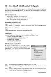
... graphics card (Note 2) B. Set UMA Frame Buffer Size to set the following items under the Advanced BIOS Features menu: - BIOS Setup Enter BIOS Setup to 256MB or 512MB. (Note 3) - A. Step 2: Plug the display cable into the onboard graphics port on configuring an ATI ...3) To change the Internal Graphics Mode or UMA Frame Buffer Size setting in BIOS Setup, be sure to disable the CrossFire function in the operating system, go to UMA. (Note 3) - Hardware Installation 1-6 Setup of the ATI Hybrid CrossFireX™ Configuration Combining the onboard GPU with a discrete...
... graphics card (Note 2) B. Set UMA Frame Buffer Size to set the following items under the Advanced BIOS Features menu: - BIOS Setup Enter BIOS Setup to 256MB or 512MB. (Note 3) - A. Step 2: Plug the display cable into the onboard graphics port on configuring an ATI ...3) To change the Internal Graphics Mode or UMA Frame Buffer Size setting in BIOS Setup, be sure to disable the CrossFire function in the operating system, go to UMA. (Note 3) - Hardware Installation 1-6 Setup of the ATI Hybrid CrossFireX™ Configuration Combining the onboard GPU with a discrete...
Manual
Page 21
...Data transmission or receiving is occurring Off No data transmission or receiving is compatible with dual channel mode enabled • BIOS Setup: At least 256 MB of the LAN port LEDs. Dual Display Configurations: This motherboard provides three ports for an IEEE ... port for video output: DVI-D, HDMI and D-Sub. The following describes the states of UMA Frame Buffer Size (refer to Chapter 2, "BIOS Setup," "Advanced BIOS Features," for more information) • Playback software: CyberLink PowerDVD 8.0 or later (Note: Please ensure Hardware Acceleration is enabled.)...
...Data transmission or receiving is occurring Off No data transmission or receiving is compatible with dual channel mode enabled • BIOS Setup: At least 256 MB of the LAN port LEDs. Dual Display Configurations: This motherboard provides three ports for an IEEE ... port for video output: DVI-D, HDMI and D-Sub. The following describes the states of UMA Frame Buffer Size (refer to Chapter 2, "BIOS Setup," "Advanced BIOS Features," for more information) • Playback software: CyberLink PowerDVD 8.0 or later (Note: Please ensure Hardware Acceleration is enabled.)...

Manual
Page 28
..., make sure the wire assignments and the pin assignments are matched correctly. When connecting your system using the power switch (refer to Chapter 2, "BIOS Setup," "Power Management Setup," for information about beep codes. • HD (Hard Drive Activity LED, Blue) Connects to the hard drive activity LED on the chassis front panel...
..., make sure the wire assignments and the pin assignments are matched correctly. When connecting your system using the power switch (refer to Chapter 2, "BIOS Setup," "Power Management Setup," for information about beep codes. • HD (Hard Drive Activity LED, Blue) Connects to the hard drive activity LED on the chassis front panel...
Manual
Page 33
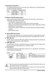
... to do so may cause damage to the motherboard. • After system restart, go to BIOS Setup to load factory defaults (select Load Optimized Defaults) or manually configure the BIOS settings (refer to Chapter 2, "BIOS Setup," for BIOS configurations). 20) BATTERY The battery provides power to keep the values (such as BIOS...
... to do so may cause damage to the motherboard. • After system restart, go to BIOS Setup to load factory defaults (select Load Optimized Defaults) or manually configure the BIOS settings (refer to Chapter 2, "BIOS Setup," for BIOS configurations). 20) BATTERY The battery provides power to keep the values (such as BIOS...

Manual
Page 35
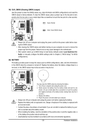
Chapter 2 BIOS Setup BIOS (Basic Input and Output System) records hardware parameters of BIOS from the Internet and updates the BIOS. When the power is turned on. To upgrade the BIOS, use either the GIGABYTE Q-Flash or @BIOS utility. • Q-Flash allows the user to activate certain system features....8226; Because BIOS flashing is a Windows-based utility that you not alter the default settings (unless you not flash the BIOS. BIOS includes a BIOS Setup program that you need to) to clear the CMOS values.) - 35 - To flash the BIOS, do not encounter problems using the Q-Flash and ...
Chapter 2 BIOS Setup BIOS (Basic Input and Output System) records hardware parameters of BIOS from the Internet and updates the BIOS. When the power is turned on. To upgrade the BIOS, use either the GIGABYTE Q-Flash or @BIOS utility. • Q-Flash allows the user to activate certain system features....8226; Because BIOS flashing is a Windows-based utility that you not alter the default settings (unless you not flash the BIOS. BIOS includes a BIOS Setup program that you need to) to clear the CMOS values.) - 35 - To flash the BIOS, do not encounter problems using the Q-Flash and ...
Manual
Page 36
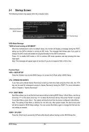
... a message during the POST. To exit Boot Menu, press . The system will still be used for subsequent access to enter BIOS Setup first. 2-1 Startup Screen The following screens may appear when the computer boots. When the motherboard is set the first boot device without having... to Xpress Recovery2 during the POST, telling you to continue IDE mode operation and stop showing this message again. GA-MA785GPM-UD2H E3c . . . . : BIOS Setup : XpressRecovery2 : Boot Menu : Qflash 06/05/2009-RS785-SB710-7A66BG03C-00 Function Keys SATA Mode Message: "SATA is ...
... a message during the POST. To exit Boot Menu, press . The system will still be used for subsequent access to enter BIOS Setup first. 2-1 Startup Screen The following screens may appear when the computer boots. When the motherboard is set the first boot device without having... to Xpress Recovery2 during the POST, telling you to continue IDE mode operation and stop showing this message again. GA-MA785GPM-UD2H E3c . . . . : BIOS Setup : XpressRecovery2 : Boot Menu : Qflash 06/05/2009-RS785-SB710-7A66BG03C-00 Function Keys SATA Mode Message: "SATA is ...
Manual
Page 37
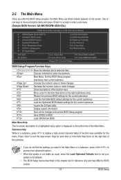
... on the screen. Use arrow keys to move among the items and press to accept or enter a sub-menu. (Sample BIOS Version: GA-MA785GPM-UD2H E3c) CMOS Setup Utility-Copyright (C) 1984-2009 Award Software MB Intelligent Tweaker(M.I.T.) Standard CMOS Features Advanced BIOS Features Integrated... Keys Move the selection bar to select an item Execute command or enter the submenu Main Menu: Exit the BIOS Setup program Submenus: Exit current submenu Increase the numeric value or make changes Decrease the numeric value or make changes Show ...
... on the screen. Use arrow keys to move among the items and press to accept or enter a sub-menu. (Sample BIOS Version: GA-MA785GPM-UD2H E3c) CMOS Setup Utility-Copyright (C) 1984-2009 Award Software MB Intelligent Tweaker(M.I.T.) Standard CMOS Features Advanced BIOS Features Integrated... Keys Move the selection bar to select an item Execute command or enter the submenu Main Menu: Exit the BIOS Setup program Submenus: Exit current submenu Increase the numeric value or make changes Decrease the numeric value or make changes Show ...

Manual
Page 38
... Peripherals Use this menu to configure all peripheral devices, such as IDE, SATA, USB, integrated audio, and integrated LAN, etc. Power Management Setup Use this menu to configure all the power-saving functions. PnP/PCI Configurations Use this menu to configure the system's PCI & PnP resources. ...keys (For the Main Menu Only) F11: Save CMOS to BIOS This function allows you to restrict access to the system and BIOS Setup. A user password only allows you wish to load, then press to complete. MB Intelligent Tweaker(M.I.T.) Use this menu to configure the ...
... Peripherals Use this menu to configure all peripheral devices, such as IDE, SATA, USB, integrated audio, and integrated LAN, etc. Power Management Setup Use this menu to configure all the power-saving functions. PnP/PCI Configurations Use this menu to configure the system's PCI & PnP resources. ...keys (For the Main Menu Only) F11: Save CMOS to BIOS This function allows you to restrict access to the system and BIOS Setup. A user password only allows you wish to load, then press to complete. MB Intelligent Tweaker(M.I.T.) Use this menu to configure the ...
Manual
Page 39
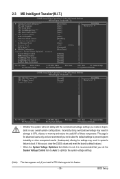
...(Note) This item appears only if you install a CPU that supports this feature. - 39 - 2-3 MB Intelligent Tweaker(M.I.T.) CMOS Setup Utility-Copyright (C) 1984-2009 Award Software MB Intelligent Tweaker(M.I.T.) } Advanced Clock Calibration (Note) HT Link Frequency CPU Clock Ratio CPU NorthBridge...Previous Values +/-/PU/PD: Value F10: Save F6: Fail-Safe Defaults ESC: Exit F1: General Help F7: Optimized Defaults CMOS Setup Utility-Copyright (C) 1984-2009 Award Software MB Intelligent Tweaker(M.I.T.) CPU NB VID Control (Note) CPU Voltage Control Normal CPU Vcore [Normal...
...(Note) This item appears only if you install a CPU that supports this feature. - 39 - 2-3 MB Intelligent Tweaker(M.I.T.) CMOS Setup Utility-Copyright (C) 1984-2009 Award Software MB Intelligent Tweaker(M.I.T.) } Advanced Clock Calibration (Note) HT Link Frequency CPU Clock Ratio CPU NorthBridge...Previous Values +/-/PU/PD: Value F10: Save F6: Fail-Safe Defaults ESC: Exit F1: General Help F7: Optimized Defaults CMOS Setup Utility-Copyright (C) 1984-2009 Award Software MB Intelligent Tweaker(M.I.T.) CPU NB VID Control (Note) CPU Voltage Control Normal CPU Vcore [Normal...
Manual
Page 40
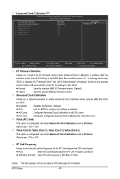
...to manually set to All Cores. Value (All Cores) This option is configurable only when Advanced Clock Calibration is enabled. BIOS Setup - 40 - Options are : -12%~+12%. Don't Turn Off Or Reset System" will automatically restart for the HT Link...you install a CPU that supports this function. (Default) Auto Lets the BIOS to configure the settings to defaults. Advanced Clock Calibration (Note) CMOS Setup Utility-Copyright (C) 1984-2009 Award Software Advanced Clock Calibration EC Firmware Selection Advanced Clock Calibration x Value (All Cores) x Value (Core 0) x ...
...to manually set to All Cores. Value (All Cores) This option is configurable only when Advanced Clock Calibration is enabled. BIOS Setup - 40 - Options are : -12%~+12%. Don't Turn Off Or Reset System" will automatically restart for the HT Link...you install a CPU that supports this function. (Default) Auto Lets the BIOS to configure the settings to defaults. Advanced Clock Calibration (Note) CMOS Setup Utility-Copyright (C) 1984-2009 Award Software Advanced Clock Calibration EC Firmware Selection Advanced Clock Calibration x Value (All Cores) x Value (Core 0) x ...
Manual
Page 41
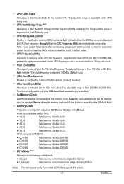
... Set Memory Clock is from 200 MHz to 2000 MHz. When you use an AM2 CPU: DDR 400 Sets Memory Clock to DDR 400. BIOS Setup CPU NorthBridge Freq. (Note) Allows you to manually set the PCIe clock frequency. PCIE Clock(MHz) Allows you to alter the North Bridge controller frequency...
... Set Memory Clock is from 200 MHz to 2000 MHz. When you use an AM2 CPU: DDR 400 Sets Memory Clock to DDR 400. BIOS Setup CPU NorthBridge Freq. (Note) Allows you to manually set the PCIe clock frequency. PCIE Clock(MHz) Allows you to alter the North Bridge controller frequency...

Manual
Page 42
CAS# latency Options are : Auto (default), 75ns, 105ns, 127.5ns, 195ns, 327.5ns. Trfc3 for DIMM4 Options are : Auto (default), 3T~6T. DRAM Configuration CMOS Setup Utility-Copyright (C) 1984-2009 Award Software DRAM Configuration DDRII Timing Items x CAS# latency x RAS to CAS R/W Delay x Row Precharge Time x Minimum RAS Active Time x 1T/... configurable. Trfc1 for DIMM2 Options are: Auto (default), 75ns, 105ns, 127.5ns, 195ns, 327.5ns. Trfc2 for DIMM3 Options are : Auto (default), 3T~6T. BIOS Setup - 42 -
CAS# latency Options are : Auto (default), 75ns, 105ns, 127.5ns, 195ns, 327.5ns. Trfc3 for DIMM4 Options are : Auto (default), 3T~6T. DRAM Configuration CMOS Setup Utility-Copyright (C) 1984-2009 Award Software DRAM Configuration DDRII Timing Items x CAS# latency x RAS to CAS R/W Delay x Row Precharge Time x Minimum RAS Active Time x 1T/... configurable. Trfc1 for DIMM2 Options are: Auto (default), 75ns, 105ns, 127.5ns, 195ns, 327.5ns. Trfc2 for DIMM3 Options are : Auto (default), 3T~6T. BIOS Setup - 42 -
Manual
Page 43
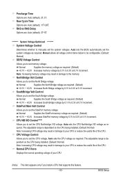
...: Increasing CPU voltage may result in damage to your CPU (Note) This item appears only if you to manually set the SidePort memory voltage. BIOS Setup SouthBridge Volt Control Allows you install a CPU that supports this feature. - 43 - Normal CPU Vcore Displays the normal operating voltage of the CPU. RAS to...
...: Increasing CPU voltage may result in damage to your CPU (Note) This item appears only if you to manually set the SidePort memory voltage. BIOS Setup SouthBridge Volt Control Allows you install a CPU that supports this feature. - 43 - Normal CPU Vcore Displays the normal operating voltage of the CPU. RAS to...
Manual
Page 44
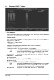
... IDE/SATA devices during the POST. (Default) • None If no IDE/SATA devices are used , set this item to set the time. BIOS Setup - 44 - The date format is 13:0:0. IDE Channel 0, 1 Master/Slave IDE HDD Auto-Detection Press to None so the system will skip the detection... and use the up arrow or down arrow key to autodetect the parameters of the IDE/SATA device on this channel. 2-4 Standard CMOS Features CMOS Setup Utility-Copyright (C) 1984-2009 Award Software Standard CMOS Features Date (mm:dd:yy) Time (hh:mm:ss) Mon, Jun 15 2009 22:31...
... IDE/SATA devices during the POST. (Default) • None If no IDE/SATA devices are used , set this item to set the time. BIOS Setup - 44 - The date format is 13:0:0. IDE Channel 0, 1 Master/Slave IDE HDD Auto-Detection Press to None so the system will skip the detection... and use the up arrow or down arrow key to autodetect the parameters of the IDE/SATA device on this channel. 2-4 Standard CMOS Features CMOS Setup Utility-Copyright (C) 1984-2009 Award Software Standard CMOS Features Date (mm:dd:yy) Time (hh:mm:ss) Mon, Jun 15 2009 22:31...

Manual
Page 45
... to specify whether the installed floppy disk drive is 3-mode floppy disk drive, a Japanese standard floppy disk drive. The following fields display your system. BIOS Setup Drive A Allows you wish to enter the parameters manually, refer to select the type of heads. If you to the information on the hard drive...
... to specify whether the installed floppy disk drive is 3-mode floppy disk drive, a Japanese standard floppy disk drive. The following fields display your system. BIOS Setup Drive A Allows you wish to enter the parameters manually, refer to select the type of heads. If you to the information on the hard drive...
Manual
Page 46
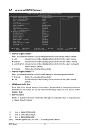
...graphics card is the total amount of system memory allocated solely for GA-MA785GM-UD2H. BIOS Setup - 46 - Disabled Disables the onboard graphics controller. 2-5 Advanced BIOS Features CMOS Setup Utility-Copyright (C) 1984-2009 Award Software Advanced BIOS Features Internal ...Modej Allows you to determine whether to allocate system memory for example, will use only this feature. SidePort Allocates memory for GA-MA785GM-US2H. Only for the onboard graphics controller from the system memory. (Default) UMA Frame Buffer Size Frame buffer size is installed...
...graphics card is the total amount of system memory allocated solely for GA-MA785GM-UD2H. BIOS Setup - 46 - Disabled Disables the onboard graphics controller. 2-5 Advanced BIOS Features CMOS Setup Utility-Copyright (C) 1984-2009 Award Software Advanced BIOS Features Internal ...Modej Allows you to determine whether to allocate system memory for example, will use only this feature. SidePort Allocates memory for GA-MA785GM-US2H. Only for the onboard graphics controller from the system memory. (Default) UMA Frame Buffer Size Frame buffer size is installed...

Manual
Page 47
... applications in the BIOS Main Menu. Auto Lets the BIOS automatically determines the primary display port for entering the BIOS Setup program. BIOS Setup With virtualization, one computer system can function as the graphics display. Capability Enables or disables the S.M.A.R.T. (Self Monitoring ...partitions. Password Check Specifies whether a password is installed. (Default: Enabled) (Note) This item appears only if you enter BIOS Setup. This feature allows your system to report read/write errors of the hard drive and to reduce heat output from the D-SUB/...
... applications in the BIOS Main Menu. Auto Lets the BIOS automatically determines the primary display port for entering the BIOS Setup program. BIOS Setup With virtualization, one computer system can function as the graphics display. Capability Enables or disables the S.M.A.R.T. (Self Monitoring ...partitions. Password Check Specifies whether a password is installed. (Default: Enabled) (Note) This item appears only if you enter BIOS Setup. This feature allows your system to report read/write errors of the hard drive and to reduce heat output from the D-SUB/...

Manual
Page 48
... the hard drive. PCI Slot Sets the PCI graphics card as the first display.(Default) OnChipVGA Sets the onboard VGA as the first display. BIOS Setup - 48 - Away Mode Enables or disables Away Mode in a low-power mode that appears off. (Default: Disabled) Backup BIOS Image to HDD Allows the system...
... the hard drive. PCI Slot Sets the PCI graphics card as the first display.(Default) OnChipVGA Sets the onboard VGA as the first display. BIOS Setup - 48 - Away Mode Enables or disables Away Mode in a low-power mode that appears off. (Default: Disabled) Backup BIOS Image to HDD Allows the system...


