Manual
Page 1
GA-MA74GMT-S2H/ GA-MA74GMT-S2 AM3 socket motherboard for AMD Phenom™ II processor/ AMD Athlon™ II processor User's Manual Rev. 1001 12ME-MA74GMT2-1001R
GA-MA74GMT-S2H/ GA-MA74GMT-S2 AM3 socket motherboard for AMD Phenom™ II processor/ AMD Athlon™ II processor User's Manual Rev. 1001 12ME-MA74GMT2-1001R
Manual
Page 2
Motherboard GA-MA74GMT-S2H/GA-MA74GMT-S2 Nov. 27, 2009 Motherboard GA-MA74GMT-S2H/ GA-MA74GMT-S2 Nov. 27, 2009
Motherboard GA-MA74GMT-S2H/GA-MA74GMT-S2 Nov. 27, 2009 Motherboard GA-MA74GMT-S2H/ GA-MA74GMT-S2 Nov. 27, 2009
Manual
Page 3
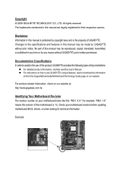
...Manual. For instructions on your motherboard revision before updating motherboard BIOS, drivers, or when looking for technical information. For product-related information, check on our website at: http://www.gigabyte.com.tw Identifying Your Motherboard Revision The revision number on how to... features in this : "REV: X.X." Check your motherboard looks like this manual may be made by any form or by GIGABYTE without GIGABYTE's prior written permission. For example, "REV: 1.0" means the revision of GIGABYTE. Disclaimer Information in this manual are legally registered to...
...Manual. For instructions on your motherboard revision before updating motherboard BIOS, drivers, or when looking for technical information. For product-related information, check on our website at: http://www.gigabyte.com.tw Identifying Your Motherboard Revision The revision number on how to... features in this : "REV: X.X." Check your motherboard looks like this manual may be made by any form or by GIGABYTE without GIGABYTE's prior written permission. For example, "REV: 1.0" means the revision of GIGABYTE. Disclaimer Information in this manual are legally registered to...
Manual
Page 4
Table of Contents Box Contents...6 Optional Items...6 GA-MA74GMT-S2H/GA-MA74GMT-S2 Motherboard Layout 7 Block Diagram...8 Chapter 1 Hardware Installation 9 1-1 Installation Precautions 9 1-2 Product Specifications 10 1-3 Installing the CPU and CPU Cooler 13 1-3-1 Installing the CPU 13 1-3-2 Installing the CPU ...
Table of Contents Box Contents...6 Optional Items...6 GA-MA74GMT-S2H/GA-MA74GMT-S2 Motherboard Layout 7 Block Diagram...8 Chapter 1 Hardware Installation 9 1-1 Installation Precautions 9 1-2 Product Specifications 10 1-3 Installing the CPU and CPU Cooler 13 1-3-1 Installing the CPU 13 1-3-2 Installing the CPU ...
Manual
Page 6
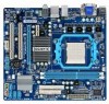
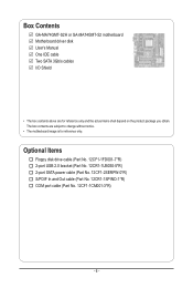
Box Contents GA-MA74GMT-S2H or GA-MA74GMT-S2 motherboard Motherboard driver disk User's Manual One IDE cable Two SATA 3Gb/s cables I/O Shield • The box contents above are subject to change without notice. • The motherboard image is for reference only and the actual items shall depend on the product package you obtain. Optional Items Floppy disk drive...
Box Contents GA-MA74GMT-S2H or GA-MA74GMT-S2 motherboard Motherboard driver disk User's Manual One IDE cable Two SATA 3Gb/s cables I/O Shield • The box contents above are subject to change without notice. • The motherboard image is for reference only and the actual items shall depend on the product package you obtain. Optional Items Floppy disk drive...
Manual
Page 7
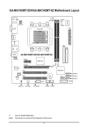
GA-MA74GMT-S2H/GA-MA74GMT-S2 Motherboard Layout KB(Note)_USB ATX_12V CPU_FAN Socket AM3 M_BIOS B_BIOS ATX IT8718 VGA DVI HDMIj R_USB USB IDE FDD LAN AUDIO GA-MA74GMT-S2H/GA-MA74GMT-S2 F_AUDIO PCIEX1 PCIEX16 RTL8111D PCI1 CD_IN CODEC PCI2 AMD 740G DDR3_1 DDR3_2 BAT COM AMD SB710 SATA2_0 SATA2_3 SATA2_2 SATA2_1 F_PANEL SPDIF_IO SYS_FAN CLR_CMOS F_USB2 F_USB1 j Only for GA-MA74GMT-S2H (Note) Use this port to connect a PS/2 keyboard or PS/2 mouse. - 7 -
GA-MA74GMT-S2H/GA-MA74GMT-S2 Motherboard Layout KB(Note)_USB ATX_12V CPU_FAN Socket AM3 M_BIOS B_BIOS ATX IT8718 VGA DVI HDMIj R_USB USB IDE FDD LAN AUDIO GA-MA74GMT-S2H/GA-MA74GMT-S2 F_AUDIO PCIEX1 PCIEX16 RTL8111D PCI1 CD_IN CODEC PCI2 AMD 740G DDR3_1 DDR3_2 BAT COM AMD SB710 SATA2_0 SATA2_3 SATA2_2 SATA2_1 F_PANEL SPDIF_IO SYS_FAN CLR_CMOS F_USB2 F_USB1 j Only for GA-MA74GMT-S2H (Note) Use this port to connect a PS/2 keyboard or PS/2 mouse. - 7 -
Manual
Page 9
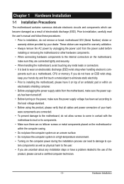
... such as a result of an antistatic pad or within an electrostatic shielding container. • Before unplugging the power supply cable from the motherboard, make sure the power supply has been turned off. • Before turning on the power, make sure they are connected tightly and ...is best to wear an electrostatic discharge (ESD) wrist strap when handling electronic com- Chapter 1 Hardware Installation 1-1 Installation Precautions The motherboard contains numerous delicate electronic circuits and components which can lead to damage to system components as well as physical harm to the user...
... such as a result of an antistatic pad or within an electrostatic shielding container. • Before unplugging the power supply cable from the motherboard, make sure the power supply has been turned off. • Before turning on the power, make sure they are connected tightly and ...is best to wear an electrostatic discharge (ESD) wrist strap when handling electronic com- Chapter 1 Hardware Installation 1-1 Installation Precautions The motherboard contains numerous delicate electronic circuits and components which can lead to damage to system components as well as physical harm to the user...
Manual
Page 12
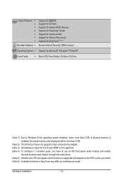
... 5) Whether the CPU fan speed control function is supported will depend on the CPU cooler you install. (Note 6) Available functions in EasyTune may differ by motherboard model.
... 5) Whether the CPU fan speed control function is supported will depend on the CPU cooler you install. (Note 6) Available functions in EasyTune may differ by motherboard model.
Manual
Page 13
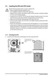
... socket.) • Apply an even and thin layer of thermal grease on the computer if the CPU cooler is not recommended that the motherboard supports the CPU. (Go to GIGABYTE's website for the peripherals. 1-3 Installing the CPU and CPU Cooler Read the following guidelines before you begin to install the CPU: •...
... socket.) • Apply an even and thin layer of thermal grease on the computer if the CPU cooler is not recommended that the motherboard supports the CPU. (Go to GIGABYTE's website for the peripherals. 1-3 Installing the CPU and CPU Cooler Read the following guidelines before you begin to install the CPU: •...
Manual
Page 14
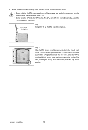
... middle of the CPU, lowering the locking lever and latching it into their holes. B. Follow the steps below to correctly install the CPU into the motherboard CPU socket. • Before installing the CPU, make sure to turn off the computer and unplug the power cord from the power outlet to prevent...
... middle of the CPU, lowering the locking lever and latching it into their holes. B. Follow the steps below to correctly install the CPU into the motherboard CPU socket. • Before installing the CPU, make sure to turn off the computer and unplug the power cord from the power outlet to prevent...
Manual
Page 15
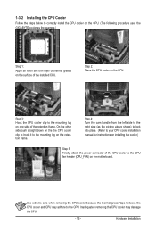
On the other side,push straight down on the the CPU cooler clip to hook it to the CPU fan header (CPU_FAN) on the motherboard. Step 4: Turn the cam handle from the left side to the right side (as the example.) Step 1: Apply an even and thin layer of thermal ... side of the retention frame. Step 3: Hook the CPU cooler clip to correctly install the CPU cooler on the CPU. (The following procedure uses the GIGABYTE cooler as the picture above shows) to lock into place. (Refer to your CPU cooler installation manual for instructions on installing the cooler.) Step 5: Finally...
On the other side,push straight down on the the CPU cooler clip to hook it to the CPU fan header (CPU_FAN) on the motherboard. Step 4: Turn the cam handle from the left side to the right side (as the example.) Step 1: Apply an even and thin layer of thermal ... side of the retention frame. Step 3: Hook the CPU cooler clip to correctly install the CPU cooler on the CPU. (The following procedure uses the GIGABYTE cooler as the picture above shows) to lock into place. (Refer to your CPU cooler installation manual for instructions on installing the cooler.) Step 5: Finally...
Manual
Page 16
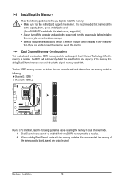
... memory mode will automatically detect the specifications and capacity of the same capacity, brand, speed, and chips be used . (Go to GIGABYTE's website for the latest memory support list.) • Always turn off the computer and unplug the power cord from the power outlet before...mode cannot be installed in Dual Channel mode. 1. A memory module can be enabled if only one DDR3 memory module is recommended that the motherboard supports the memory. Hardware Installation - 16 - 1-4 Installing the Memory Read the following guidelines before installing the memory in only one memory ...
... memory mode will automatically detect the specifications and capacity of the same capacity, brand, speed, and chips be used . (Go to GIGABYTE's website for the latest memory support list.) • Always turn off the computer and unplug the power cord from the power outlet before...mode cannot be installed in Dual Channel mode. 1. A memory module can be enabled if only one DDR3 memory module is recommended that the motherboard supports the memory. Hardware Installation - 16 - 1-4 Installing the Memory Read the following guidelines before installing the memory in only one memory ...
Manual
Page 17
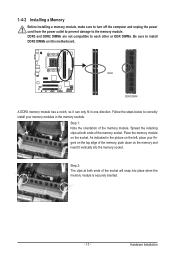
... and unplug the power cord from the power outlet to prevent damage to install DDR3 DIMMs on the socket. Place the memory module on this motherboard. Hardware Installation Spread the retaining clips at both ends of the socket will snap into the memory socket. Follow the steps below to correctly install...
... and unplug the power cord from the power outlet to prevent damage to install DDR3 DIMMs on the socket. Place the memory module on this motherboard. Hardware Installation Spread the retaining clips at both ends of the socket will snap into the memory socket. Follow the steps below to correctly install...
Manual
Page 18
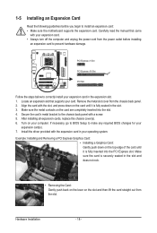
... expansion slot. 1. PCI Express x1 Slot PCI Express x16 Slot PCI Slot Follow the steps below to install an expansion card: • Make sure the motherboard supports the expansion card. Turn on the slot and then lift the card straight out from the chassis back panel. 2.
... expansion slot. 1. PCI Express x1 Slot PCI Express x16 Slot PCI Slot Follow the steps below to install an expansion card: • Make sure the motherboard supports the expansion card. Turn on the slot and then lift the card straight out from the chassis back panel. 2.
Manual
Page 20
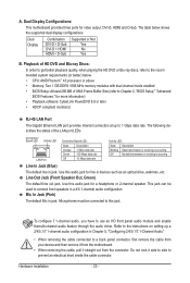
... such as an optical drive, walkman, etc. Line Out Jack (Front Speaker Out, Green) The default line out jack. Dual Display Configurations: This motherboard provides three ports for a headphone or 2-channel speaker. The table below . • CPU: AMD Phenom™ X3 processor or above • ...jack. Do not rock it side to side to a back panel connector, first remove the cable from your device and then remove it from the motherboard. • When removing the cable, pull it straight out from the connector. A. Dual Display Combination DVI-D + D-Sub DVI-D + HDMI HDMI...
... such as an optical drive, walkman, etc. Line Out Jack (Front Speaker Out, Green) The default line out jack. Dual Display Configurations: This motherboard provides three ports for a headphone or 2-channel speaker. The table below . • CPU: AMD Phenom™ X3 processor or above • ...jack. Do not rock it side to side to a back panel connector, first remove the cable from your device and then remove it from the motherboard. • When removing the cable, pull it straight out from the connector. A. Dual Display Combination DVI-D + D-Sub DVI-D + HDMI HDMI...

Manual
Page 21
... connectors you wish to connect. • Before installing the devices, be sure to the devices. • After installing the device and before turning on the motherboard. - 21 -
... connectors you wish to connect. • Before installing the devices, be sure to the devices. • After installing the device and before turning on the motherboard. - 21 -

Manual
Page 22
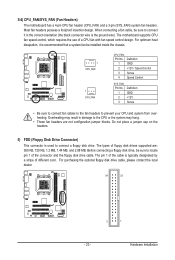
Before connecting the power connector, first make sure the power supply is turned off and all the components on the motherboard. The 12V power connector mainly supplies power to the power connector in the correct orientation. When using a 2x10 power supply. 21 43 ATX_12V ATX_12V... power supply cable into pins under the protective cover when using a 2x12 power supply, remove the protective cover from the main power connector on the motherboard. Connect the power supply cable to the CPU. If a power supply is used that can withstand high power consumption be used (500W or greater)....
Before connecting the power connector, first make sure the power supply is turned off and all the components on the motherboard. The 12V power connector mainly supplies power to the power connector in the correct orientation. When using a 2x10 power supply. 21 43 ATX_12V ATX_12V... power supply cable into pins under the protective cover when using a 2x12 power supply, remove the protective cover from the main power connector on the motherboard. Connect the power supply cable to the CPU. If a power supply is used that can withstand high power consumption be used (500W or greater)....
Manual
Page 23
... sure to connect a floppy disk drive. For purchasing the optional floppy disk drive cable, please contact the local dealer. 34 33 2 1 - 23 - Hardware Installation The motherboard supports CPU fan speed control, which requires the use of the cable is used to locate pin 1 of the connector and the floppy disk drive... fan headers are : 360 KB, 720 KB, 1.2 MB, 1.44 MB, and 2.88 MB. Most fan headers possess a foolproof insertion design. 3/4) CPU_FAN/SYS_FAN (Fan Headers) The motherboard has a 4-pin CPU fan header (CPU_FAN) and a 3-pin (SYS_FAN) system fan headers.
... sure to connect a floppy disk drive. For purchasing the optional floppy disk drive cable, please contact the local dealer. 34 33 2 1 - 23 - Hardware Installation The motherboard supports CPU fan speed control, which requires the use of the cable is used to locate pin 1 of the connector and the floppy disk drive... fan headers are : 360 KB, 720 KB, 1.2 MB, 1.44 MB, and 2.88 MB. Most fan headers possess a foolproof insertion design. 3/4) CPU_FAN/SYS_FAN (Fan Headers) The motherboard has a 4-pin CPU fan header (CPU_FAN) and a 3-pin (SYS_FAN) system fan headers.
Manual
Page 26
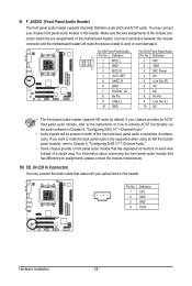
... match the pin assignments of the front and back panel audio connections simultaneously. Incorrect connection between the module connector and the motherboard header will be present on both of the motherboard header. If you want to mute the back panel audio (only supported when using an HD front panel audio module), refer...
... match the pin assignments of the front and back panel audio connections simultaneously. Incorrect connection between the module connector and the motherboard header will be present on both of the motherboard header. If you want to mute the back panel audio (only supported when using an HD front panel audio module), refer...
Manual
Page 28
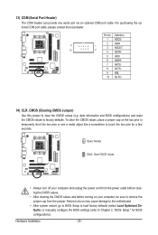
... Values • Always turn off your computer, be sure to Chapter 2, "BIOS Setup," for a few seconds. Failure to do so may cause damage to the motherboard. • After system restart, go to BIOS Setup to load factory defaults (select Load Optimized Defaults) or manually configure the BIOS settings (refer to remove...
... Values • Always turn off your computer, be sure to Chapter 2, "BIOS Setup," for a few seconds. Failure to do so may cause damage to the motherboard. • After system restart, go to BIOS Setup to load factory defaults (select Load Optimized Defaults) or manually configure the BIOS settings (refer to remove...


