Manual
Page 1
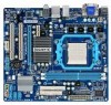
GA-MA74GMT-S2H/ GA-MA74GMT-S2 AM3 socket motherboard for AMD Phenom™ II processor/ AMD Athlon™ II processor User's Manual Rev. 1001 12ME-MA74GMT2-1001R
GA-MA74GMT-S2H/ GA-MA74GMT-S2 AM3 socket motherboard for AMD Phenom™ II processor/ AMD Athlon™ II processor User's Manual Rev. 1001 12ME-MA74GMT2-1001R
Manual
Page 3
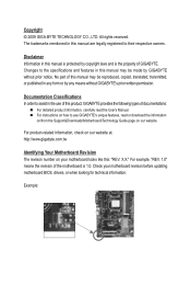
Documentation Classifications In order to the specifications and features in this manual may be reproduced, copied, translated, transmitted, or published in this product, GIGABYTE provides the following types of GIGABYTE. Example: All rights reserved. Disclaimer Information in any form or by GIGABYTE without GIGABYTE's prior written permission. Changes to assist in this : "REV: X.X." For product-related...
Documentation Classifications In order to the specifications and features in this manual may be reproduced, copied, translated, transmitted, or published in this product, GIGABYTE provides the following types of GIGABYTE. Example: All rights reserved. Disclaimer Information in any form or by GIGABYTE without GIGABYTE's prior written permission. Changes to assist in this : "REV: X.X." For product-related...
Manual
Page 5
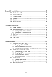
Chapter 3 Drivers Installation 55 3-1 Installing Chipset Drivers 55 3-2 Application Software 56 3-3 Technical Manuals 56 3-4 Contact...57 3-5 System...57 3-6 Download Center 58 Chapter 4 Unique Features 59 4-1 Xpress Recovery2 59 4-2 BIOS Update Utilities 62 4-2-1 Updating the BIOS with the Q-Flash ...
Chapter 3 Drivers Installation 55 3-1 Installing Chipset Drivers 55 3-2 Application Software 56 3-3 Technical Manuals 56 3-4 Contact...57 3-5 System...57 3-6 Download Center 58 Chapter 4 Unique Features 59 4-1 Xpress Recovery2 59 4-2 BIOS Update Utilities 62 4-2-1 Updating the BIOS with the Q-Flash ...
Manual
Page 6
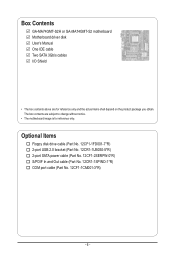
... No. 12CF1-2SERPW-0*R) S/PDIF In and Out cable (Part No. 12CR1-1SPINO-1*R) COM port cable (Part No. 12CF1-1CM001-3*R) - 6 - Box Contents GA-MA74GMT-S2H or GA-MA74GMT-S2 motherboard Motherboard driver disk User's Manual One IDE cable Two SATA 3Gb/s cables I/O Shield • The box contents above are subject to change without notice. • The motherboard...
... No. 12CF1-2SERPW-0*R) S/PDIF In and Out cable (Part No. 12CR1-1SPINO-1*R) COM port cable (Part No. 12CF1-1CM001-3*R) - 6 - Box Contents GA-MA74GMT-S2H or GA-MA74GMT-S2 motherboard Motherboard driver disk User's Manual One IDE cable Two SATA 3Gb/s cables I/O Shield • The box contents above are subject to change without notice. • The motherboard...
Manual
Page 9
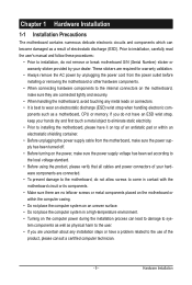
These stickers are required for warranty validation. • Always remove the AC power by your dealer. Prior to installation, carefully read the user's manual and follow these procedures: • Prior to installation, do not remove or break motherboard S/N (Serial Number) sticker or warranty sticker provided by unplugging the power ...
These stickers are required for warranty validation. • Always remove the AC power by your dealer. Prior to installation, carefully read the user's manual and follow these procedures: • Prior to installation, do not remove or break motherboard S/N (Serial Number) sticker or warranty sticker provided by unplugging the power ...
Manual
Page 15
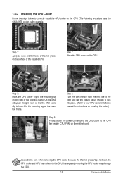
... the steps below to correctly install the CPU cooler on the CPU. (The following procedure uses the GIGABYTE cooler as the picture above shows) to lock into place. (Refer to your CPU cooler installation manual for instructions on installing the cooler.) Step 5: Finally, attach the power connector of the CPU cooler to...
... the steps below to correctly install the CPU cooler on the CPU. (The following procedure uses the GIGABYTE cooler as the picture above shows) to lock into place. (Refer to your CPU cooler installation manual for instructions on installing the cooler.) Step 5: Finally, attach the power connector of the CPU cooler to...
Manual
Page 18
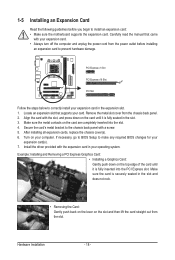
... out from the slot. Secure the card's metal bracket to the chassis back panel with the expansion card in the expansion slot. 1. Carefully read the manual that supports your operating system. Make sure the metal contacts on your expansion card. • Always turn off the computer and unplug the power cord...
... out from the slot. Secure the card's metal bracket to the chassis back panel with the expansion card in the expansion slot. 1. Carefully read the manual that supports your operating system. Make sure the metal contacts on your expansion card. • Always turn off the computer and unplug the power cord...
Manual
Page 28
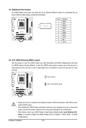
... do so may cause damage to the motherboard. • After system restart, go to BIOS Setup to load factory defaults (select Load Optimized Defaults) or manually configure the BIOS settings (refer to remove the jumper cap from the jumper. To clear the CMOS values, place a jumper cap on your computer, be...
... do so may cause damage to the motherboard. • After system restart, go to BIOS Setup to load factory defaults (select Load Optimized Defaults) or manually configure the BIOS settings (refer to remove the jumper cap from the jumper. To clear the CMOS values, place a jumper cap on your computer, be...
Manual
Page 36
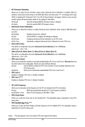
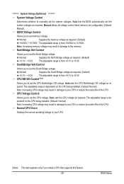
... whether to alter the clock ratio for a few seconds and the system will appear. Options are : -12%~+12%. Options are: Auto (default), Manual. Wait for the installed CPU. CPU core 2 Enables or disables CPU Core 2. (Default: Enabled) CPU core 3 (Note) Enables or disables CPU... Individually configures Advanced Clock Calibration for all CPU cores (number of cores available depends on the CPU being used). Manual Allows you to manually enable/disable CPU Core 2 and Core 3. EC Firmware Selection Allows you to select the EC firmware version when Advanced...
... whether to alter the clock ratio for a few seconds and the system will appear. Options are : -12%~+12%. Options are: Auto (default), Manual. Wait for the installed CPU. CPU core 2 Enables or disables CPU Core 2. (Default: Enabled) CPU core 3 (Note) Enables or disables CPU... Individually configures Advanced Clock Calibration for all CPU cores (number of cores available depends on the CPU being used). Manual Allows you to manually enable/disable CPU Core 2 and Core 3. EC Firmware Selection Allows you to select the EC firmware version when Advanced...
Manual
Page 37
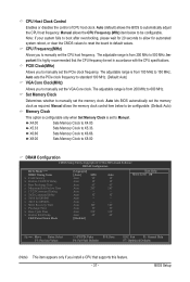
... x Trfc2 for automated system reboot, or clear the CMOS values to reset the board to Manual. Auto -- BIOS Setup Manual allows the CPU Frequency (MHz) item below to manually set the memory clock. Manual allows the memory clock control item below to be configurable. (Default: Auto) Memory Clock This...of CPU host clock. The adjustable range is highly recommended that supports this feature. - 37 - Important It is from 200 MHz to manually set in accordance with the CPU specifications. PCIE Clock(MHz) Allows you install a CPU that the CPU frequency be set the PCIe clock ...
... x Trfc2 for automated system reboot, or clear the CMOS values to reset the board to Manual. Auto -- BIOS Setup Manual allows the CPU Frequency (MHz) item below to manually set the memory clock. Manual allows the memory clock control item below to be configurable. (Default: Auto) Memory Clock This...of CPU host clock. The adjustable range is highly recommended that supports this feature. - 37 - Important It is from 200 MHz to manually set in accordance with the CPU specifications. PCIE Clock(MHz) Allows you install a CPU that the CPU frequency be set the PCIe clock ...
Manual
Page 38
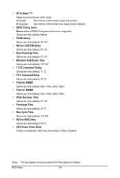
Unganged Sets memory control mode to two single-channel. (Default) DDR3 Timing Items Manual allows all DDR3 Timing items below to single dual-channel. Row Precharge Time Options are : Auto (default), 5T~12T. Trfc0 for DIMM2 Options are: Auto (... : Auto (default), 11T~42T. Row Cycle Time Options are : Auto (default), 1T, 2T. Options are : Auto (default), 4T~12T. CAS# latency Options are : Auto (default), Manual. RAS to set memory control mode. DCTs Mode (Note) Allows you install a CPU that supports this feature. RAS to RAS Delay Options are: Auto (default...
Unganged Sets memory control mode to two single-channel. (Default) DDR3 Timing Items Manual allows all DDR3 Timing items below to single dual-channel. Row Precharge Time Options are : Auto (default), 5T~12T. Trfc0 for DIMM2 Options are: Auto (... : Auto (default), 11T~42T. Row Cycle Time Options are : Auto (default), 1T, 2T. Options are : Auto (default), 4T~12T. CAS# latency Options are : Auto (default), Manual. RAS to set memory control mode. DCTs Mode (Note) Allows you install a CPU that supports this feature. RAS to RAS Delay Options are: Auto (default...
Manual
Page 39
...Allows you to set memory voltage. The adjustable range is from +0.1V to your CPU (Note) This item appears only if you to manually set the system voltages. Note: Increasing memory voltage may result in damage to set the South Bridge voltage. Normal Supplies the South Bridge ...memory. Auto sets the CPU Northbridge VID voltage as required. Auto sets the CPU voltage as required. BIOS Setup Manual allows all voltage control items below to be configurable. (Default: Manual) DDR3 Voltage Control Allows you to +0.750V. CPU NB VID Control (Note) Allows you to set the ...
...Allows you to set memory voltage. The adjustable range is from +0.1V to your CPU (Note) This item appears only if you to manually set the system voltages. Note: Increasing memory voltage may result in damage to set the South Bridge voltage. Normal Supplies the South Bridge ...memory. Auto sets the CPU Northbridge VID voltage as required. Auto sets the CPU voltage as required. BIOS Setup Manual allows all voltage control items below to be configurable. (Default: Manual) DDR3 Voltage Control Allows you to +0.750V. CPU NB VID Control (Note) Allows you to set the ...
Manual
Page 41
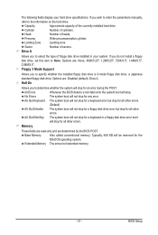
... drive, set this item to None. Cylinder Number of sectors. Precomp Write precompensation cylinder. Sector Number of cylinders. If you wish to enter the parameters manually, refer to select the type of extended memory. - 41 - Options are: Disabled (default), Drive A. No Errors The system boot will stop . Base Memory Also called...
... drive, set this item to None. Cylinder Number of sectors. Precomp Write precompensation cylinder. Sector Number of cylinders. If you wish to enter the parameters manually, refer to select the type of extended memory. - 41 - Options are: Disabled (default), Drive A. No Errors The system boot will stop . Base Memory Also called...
Manual
Page 55
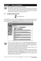
...) (e.g. You can click the Install All button and "Xpress Install" will then autodetect and install the USB 2.0 driver.) - 55 - Or click Install Single Items to manually select the drivers you wish to do so may affect the driver installation. • Some device drivers will continue to install other applications included in...
...) (e.g. You can click the Install All button and "Xpress Install" will then autodetect and install the USB 2.0 driver.) - 55 - Or click Install Single Items to manually select the drivers you wish to do so may affect the driver installation. • Some device drivers will continue to install other applications included in...
Manual
Page 56
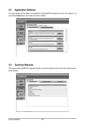
Drivers Installation - 56 - You can click the Install button on the right of an item to install it. 3-3 Technical Manuals This page provides GIGABYTE's application guides, content descriptions for this driver disk, and the motherboard manuals. 3-2 Application Software This page displays all the utilities and applications that GIGABYTE develops and some free software.
Drivers Installation - 56 - You can click the Install button on the right of an item to install it. 3-3 Technical Manuals This page provides GIGABYTE's application guides, content descriptions for this driver disk, and the motherboard manuals. 3-2 Application Software This page displays all the utilities and applications that GIGABYTE develops and some free software.
Manual
Page 62
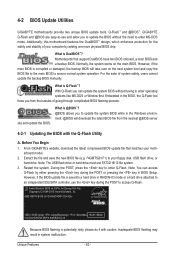
... drive. What is DualBIOS™? From GIGABYTE's website, download the latest compressed BIOS update file that support DualBIOS have two BIOS onboard, a main BIOS and a backup BIOS. Restart the system. Additionally, this motherboard features the DualBIOS™ design, which enhances protection for GA-MA74GMT-S2H E3c . . . . : ... A. Before You Begin 1. AMD RS740 BIOS for the safety and stability of system safety, users cannot update the backup BIOS manually. Note: You can update the system BIOS without the need to enter operating systems like MS-DOS or Window first. With ...
... drive. What is DualBIOS™? From GIGABYTE's website, download the latest compressed BIOS update file that support DualBIOS have two BIOS onboard, a main BIOS and a backup BIOS. Restart the system. Additionally, this motherboard features the DualBIOS™ design, which enhances protection for GA-MA74GMT-S2H E3c . . . . : ... A. Before You Begin 1. AMD RS740 BIOS for the safety and stability of system safety, users cannot update the backup BIOS manually. Note: You can update the system BIOS without the need to enter operating systems like MS-DOS or Window first. With ...
Manual
Page 65
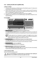
... You Begin 1. If the BIOS update file for example, avoid a power loss or switching off the Internet). Unique Features Do not use the G.O.M. (GIGABYTE Online Management) function when using @BIOS. 4. Follow the on -screen instructions to complete. C. Using @BIOS 1. Load BIOS Defaults after BIOS Update: Select...load BIOS defaults after BIOS update and after updating the BIOS. Make sure that is not present on the @BIOS server site, please manually download the BIOS update file from File, then select the location where you save the current BIOS file. 4. B. 4-2-2 Updating the ...
... You Begin 1. If the BIOS update file for example, avoid a power loss or switching off the Internet). Unique Features Do not use the G.O.M. (GIGABYTE Online Management) function when using @BIOS. 4. Follow the on -screen instructions to complete. C. Using @BIOS 1. Load BIOS Defaults after BIOS Update: Select...load BIOS defaults after BIOS update and after updating the BIOS. Make sure that is not present on the @BIOS server site, please manually download the BIOS update file from File, then select the location where you save the current BIOS file. 4. B. 4-2-2 Updating the ...

Manual
Page 72
... ---- LD 8 ---- Option ROM Utility (c) 2008 Advanced Micro Devices, Inc. [ Define LD Menu ] LD No RAID Mode LD 1 ---- Create Arrays Manually To create a new array, press to enter the RAID configuration menu (Figure 5). LD 7 ---- LD 10 ---- LD No RAID Mode [ Define LD ...Menu ] Total Drv LD 1 RAID 0 0 Stripe Block: 64 KB Gigabyte Boundary: ON [ Drives Assignments ] Channel:ID Drive Model 1:Mas WDC WD800JD-22LSA0 2:Mas WDC WD800JD-22LSA0 Capabilities SATA 3G SATA 3G Fast...
... ---- LD 8 ---- Option ROM Utility (c) 2008 Advanced Micro Devices, Inc. [ Define LD Menu ] LD No RAID Mode LD 1 ---- Create Arrays Manually To create a new array, press to enter the RAID configuration menu (Figure 5). LD 7 ---- LD 10 ---- LD No RAID Mode [ Define LD ...Menu ] Total Drv LD 1 RAID 0 0 Stripe Block: 64 KB Gigabyte Boundary: ON [ Drives Assignments ] Channel:ID Drive Model 1:Mas WDC WD800JD-22LSA0 2:Mas WDC WD800JD-22LSA0 Capabilities SATA 3G SATA 3G Fast...
Manual
Page 81
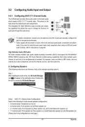
... instructions use Windows Vista as the example operating system.) Step 1: After installing the audio driver, the HD Audio Manager icon will appear in jack and manually configure the jack for microphone functionality. • Audio signals will be simultaneously processed. For example, users can listen to change the function for multi-channel...
... instructions use Windows Vista as the example operating system.) Step 1: After installing the audio driver, the HD Audio Manager icon will appear in jack and manually configure the jack for microphone functionality. • Audio signals will be simultaneously processed. For example, users can listen to change the function for multi-channel...
Manual
Page 92
...this text. WEEE Symbol Statement The symbol shown below is recycled in a manner that the information in your product's user's manual and we at the time of disposal will be taken to add and safe from the 2002/96/EC WEEE (Waste ...for errors or omissions in Electrical and Electronic Equipment) and WEEE (Waste Electrical and Electronic Equipment) environmental directives, as well as a commitment by GIGABYTE. GIGABYTE cannot, however, assume any unauthorized purpose. The WEEE Directive specifies the treatment, collection, recycling and disposal of life" product. w When your...
...this text. WEEE Symbol Statement The symbol shown below is recycled in a manner that the information in your product's user's manual and we at the time of disposal will be taken to add and safe from the 2002/96/EC WEEE (Waste ...for errors or omissions in Electrical and Electronic Equipment) and WEEE (Waste Electrical and Electronic Equipment) environmental directives, as well as a commitment by GIGABYTE. GIGABYTE cannot, however, assume any unauthorized purpose. The WEEE Directive specifies the treatment, collection, recycling and disposal of life" product. w When your...


