Manual
Page 1
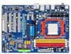
GA-M720-US3 AM2+/AM2 socket motherboard for AMD PhenomTM FX processor/AMD PhenomTM X4 processor/ AMD PhenomTM X3 processor/AMD AthlonTM X2 processor/ AMD AthlonTM processor/AMD SempronTM X2 processor/ AMD SempronTM processor User's Manual Rev. 1002 12ME-M720US3-1002R
GA-M720-US3 AM2+/AM2 socket motherboard for AMD PhenomTM FX processor/AMD PhenomTM X4 processor/ AMD PhenomTM X3 processor/AMD AthlonTM X2 processor/ AMD AthlonTM processor/AMD SempronTM X2 processor/ AMD SempronTM processor User's Manual Rev. 1002 12ME-M720US3-1002R
Manual
Page 2
Motherboard GA-M720-US3 Dec. 8, 2008 Motherboard GA-M720-US3 Dec. 8, 2008
Motherboard GA-M720-US3 Dec. 8, 2008 Motherboard GA-M720-US3 Dec. 8, 2008
Manual
Page 4
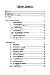
Table of Contents Box Contents ...6 OptionalItems...6 GA-M720-US3 Motherboard Layout 7 Block Diagram...8 Chapter 1 Hardware Installation 9 1-1 Installation Precautions 9 1-2 Product Specifications 10 1-3 Installing the CPU and CPU Cooler 12 1-3-1 Installing the CPU 12 1-3-2 Installing the ...
Table of Contents Box Contents ...6 OptionalItems...6 GA-M720-US3 Motherboard Layout 7 Block Diagram...8 Chapter 1 Hardware Installation 9 1-1 Installation Precautions 9 1-2 Product Specifications 10 1-3 Installing the CPU and CPU Cooler 12 1-3-1 Installing the CPU 12 1-3-2 Installing the ...
Manual
Page 6
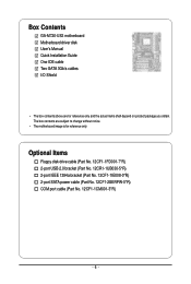
...-1IE008-0*R) 2-port SATA power cable (Part No. 12CF1-2SERPW-0*R) COM port cable (Part No. 12CF1-1CM001-3*R) - 6 - The box contents are for reference only. Box Contents GA-M720-US3 motherboard Motherboard driver disk User's Manual Quick Installation Guide One IDE cable Two SATA 3Gb/s cables I/O Shield • The box contents above are subject to...
...-1IE008-0*R) 2-port SATA power cable (Part No. 12CF1-2SERPW-0*R) COM port cable (Part No. 12CF1-1CM001-3*R) - 6 - The box contents are for reference only. Box Contents GA-M720-US3 motherboard Motherboard driver disk User's Manual Quick Installation Guide One IDE cable Two SATA 3Gb/s cables I/O Shield • The box contents above are subject to...
Manual
Page 10
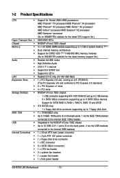
...drive connector 1 x IDE connector 6 x SATA 3Gb/s connectors 1 x CPU fan header 2 x system fan headers 1 x power fan header 1 x front panel header GA-M720-US3 Motherboard - 10 - 1-2 Product Specifications CPU Hyper Transport Bus Chipset Memory Audio ...memory (Note 1) Dual channel memory architecture Support for DDR2 1200 (Note 2)/1066/800 MHz memory modules (Go to GIGABYTE's website for the latest memory support list.) Realtek ALC888 codec High Definition Audio 2/4/5.1/7.1-channel Support for S/PDIF Out ...
...drive connector 1 x IDE connector 6 x SATA 3Gb/s connectors 1 x CPU fan header 2 x system fan headers 1 x power fan header 1 x front panel header GA-M720-US3 Motherboard - 10 - 1-2 Product Specifications CPU Hyper Transport Bus Chipset Memory Audio ...memory (Note 1) Dual channel memory architecture Support for DDR2 1200 (Note 2)/1066/800 MHz memory modules (Go to GIGABYTE's website for the latest memory support list.) Realtek ALC888 codec High Definition Audio 2/4/5.1/7.1-channel Support for S/PDIF Out ...
Manual
Page 12
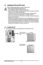
mended that the motherboard supports the CPU. (Go to GIGABYTE's website for the peripherals. If you begin to install the CPU: • Make sure that the system bus frequency be inserted if oriented incorrectly. • ... Denotes Pin One of the CPU. Locate the pin one of the Socket AM2 Socket A Small Triangle Marking Denotes CPU Pin One AM2+/AM2 CPU GA-M720-US3 Motherboard - 12 - 1-3 Installing the CPU and CPU Cooler Read the following guidelines before installing the CPU to your hardware specifications including the CPU, graphics card...
mended that the motherboard supports the CPU. (Go to GIGABYTE's website for the peripherals. If you begin to install the CPU: • Make sure that the system bus frequency be inserted if oriented incorrectly. • ... Denotes Pin One of the CPU. Locate the pin one of the Socket AM2 Socket A Small Triangle Marking Denotes CPU Pin One AM2+/AM2 CPU GA-M720-US3 Motherboard - 12 - 1-3 Installing the CPU and CPU Cooler Read the following guidelines before installing the CPU to your hardware specifications including the CPU, graphics card...
Manual
Page 14
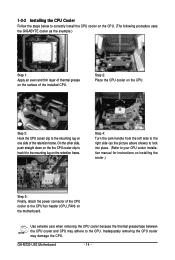
...Step 5: Finally, attach the power connector of the CPU cooler to correctly install the CPU cooler on the CPU. (The following procedure uses the GIGABYTE cooler as the example.) Step 1: Apply an even and thin layer of thermal grease on the surface of the retention frame. 1-3-2 Installing the CPU...on the motherboard. Step 2: Place the CPU cooler on one side of the installed CPU. Inadequately removing the CPU cooler may adhere to the CPU. GA-M720-US3 Motherboard - 14 - Step 3: Hook the CPU cooler clip to the mounting lug on the retention frame. On the other side, push straight down...
...Step 5: Finally, attach the power connector of the CPU cooler to correctly install the CPU cooler on the CPU. (The following procedure uses the GIGABYTE cooler as the example.) Step 1: Apply an even and thin layer of thermal grease on the surface of the retention frame. 1-3-2 Installing the CPU...on the motherboard. Step 2: Place the CPU cooler on one side of the installed CPU. Inadequately removing the CPU cooler may adhere to the CPU. GA-M720-US3 Motherboard - 14 - Step 3: Hook the CPU cooler clip to the mounting lug on the retention frame. On the other side, push straight down...
Manual
Page 16
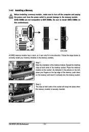
... socket. Step 2: The clips at both ends of the memory socket. DDR2 DIMMs are not compatible to DDR DIMMs. Be sure to the memory module. GA-M720-US3 Motherboard - 16 - Notch DDR2 DIMM A DDR2 memory module has a notch, so it vertically into place when the memory module is securely inserted. Spread the retaining...
... socket. Step 2: The clips at both ends of the memory socket. DDR2 DIMMs are not compatible to DDR DIMMs. Be sure to the memory module. GA-M720-US3 Motherboard - 16 - Notch DDR2 DIMM A DDR2 memory module has a notch, so it vertically into place when the memory module is securely inserted. Spread the retaining...
Manual
Page 18
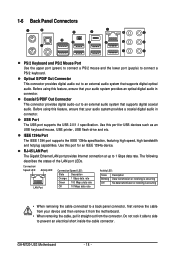
Use this port for USB devices such as an USB keyboard/mouse, USB printer, USB flash drive and etc. GA-M720-US3 Motherboard - 18 - Use this port for an IEEE 1394a device. RJ-45 LAN Port The Gigabit Ethernet LAN port provides Internet connection at up to ...
Use this port for USB devices such as an USB keyboard/mouse, USB printer, USB flash drive and etc. GA-M720-US3 Motherboard - 18 - Use this port for an IEEE 1394a device. RJ-45 LAN Port The Gigabit Ethernet LAN port provides Internet connection at up to ...
Manual
Page 20
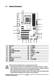
... device and before connecting external devices: • First make sure the device cable has been securely attached to turn off the devices and your computer. GA-M720-US3 Motherboard - 20 -
... device and before connecting external devices: • First make sure the device cable has been securely attached to turn off the devices and your computer. GA-M720-US3 Motherboard - 20 -
Manual
Page 22
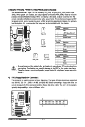
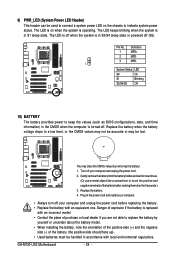
...) system fan headers, and a 3-pin power fan header (PWR_FAN). The motherboard supports CPU fan speed control, which requires the use of different color. 33 1 34 2 GA-M720-US3 Motherboard - 22 - Definition 1 GND 2 +12V 3 Sense • Be sure to connect fan cables to the fan headers to prevent your CPU and system from overheating...
...) system fan headers, and a 3-pin power fan header (PWR_FAN). The motherboard supports CPU fan speed control, which requires the use of different color. 33 1 34 2 GA-M720-US3 Motherboard - 22 - Definition 1 GND 2 +12V 3 Sense • Be sure to connect fan cables to the fan headers to prevent your CPU and system from overheating...
Manual
Page 24
... and wait for 5 seconds.) 3. Turn off your computer and unplug the power cord before replacing the battery. • Replace the battery with local environmental regulations. GA-M720-US3 Motherboard - 24 - Pin No. Replace the battery. 4. Plug in the power cord and restart your computer. • Always turn off . Replace the battery when the...
... and wait for 5 seconds.) 3. Turn off your computer and unplug the power cord before replacing the battery. • Replace the battery with local environmental regulations. GA-M720-US3 Motherboard - 24 - Pin No. Replace the battery. 4. Plug in the power cord and restart your computer. • Always turn off . Replace the battery when the...
Manual
Page 26
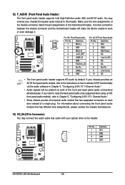
Incorrect connection between the module connector and the motherboard header will be present on both of the motherboard header. Definition 1 CD-L 1 2 GND 3 GND 4 CD-R GA-M720-US3 Motherboard - 26 - 12) F_AUDIO (Front Panel Audio Header) The front panel audio header supports Intel High Definition audio (HD) and AC'97 audio. Make sure ...
Incorrect connection between the module connector and the motherboard header will be present on both of the motherboard header. Definition 1 CD-L 1 2 GND 3 GND 4 CD-R GA-M720-US3 Motherboard - 26 - 12) F_AUDIO (Front Panel Audio Header) The front panel audio header supports Intel High Definition audio (HD) and AC'97 audio. Make sure ...
Manual
Page 28
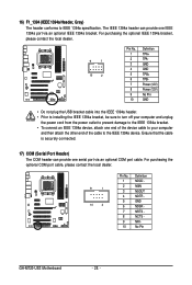
... optional COM port cable, please contact the local dealer. 9 1 10 2 Pin No. 1 2 3 4 5 6 7 8 9 10 Definition NDCD NSIN NSOUT NDTR GND NDSR NRTS NCTS NRI No Pin GA-M720-US3 Motherboard - 28 - For purchasing the optional IEEE 1394a bracket, please contact the local dealer. 9 1 10 2 Pin No. 1 2 3 4 5 6 7 8 9 10 Definition TPA+ TPAGND GND TPB+ TPBPower (12V...
... optional COM port cable, please contact the local dealer. 9 1 10 2 Pin No. 1 2 3 4 5 6 7 8 9 10 Definition NDCD NSIN NSOUT NDTR GND NDSR NRTS NCTS NRI No Pin GA-M720-US3 Motherboard - 28 - For purchasing the optional IEEE 1394a bracket, please contact the local dealer. 9 1 10 2 Pin No. 1 2 3 4 5 6 7 8 9 10 Definition TPA+ TPAGND GND TPB+ TPBPower (12V...
Manual
Page 32
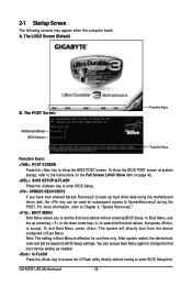
... boot device without having to the instructions on the Full Screen LOGO Show item on BIOS Setup settings. Note: The setting in Boot Menu. GA-M720-US3 Motherboard - 32 - M720-US3 F1ec . . . . : BIOS Setup : XpressRecovery2 : Boot Menu : Qflash 12/26/2008-NF-MCP78-6A610G06C-00 Function Keys Function Keys Function Keys: : POST SCREEN Press the...
... boot device without having to the instructions on the Full Screen LOGO Show item on BIOS Setup settings. Note: The setting in Boot Menu. GA-M720-US3 Motherboard - 32 - M720-US3 F1ec . . . . : BIOS Setup : XpressRecovery2 : Boot Menu : Qflash 12/26/2008-NF-MCP78-6A610G06C-00 Function Keys Function Keys Function Keys: : POST SCREEN Press the...
Manual
Page 34
... the power-saving functions. PnP/PCI Configurations Use this menu to configure the system's PCI & PnP resources. PC Health Status Use this task.) GA-M720-US3 Motherboard - 34 - Pressing to the confirmation message will exit BIOS Setup. (Pressing can create up to the system and BIOS Setup. An user password only...
... the power-saving functions. PnP/PCI Configurations Use this menu to configure the system's PCI & PnP resources. PC Health Status Use this task.) GA-M720-US3 Motherboard - 34 - Pressing to the confirmation message will exit BIOS Setup. (Pressing can create up to the system and BIOS Setup. An user password only...
Manual
Page 36
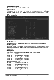
...-Safe Defaults ESC: Exit F1: General Help F7: Optimized Defaults SLI-Ready Memory Allows you use a AM2 CPU: DDR 400 Sets Memory Clock to Manual. GA-M720-US3 Motherboard - 36 - DRAM Configuration CMOS Setup Utility-Copyright (C) 1984-2008 Award Software DRAM Configuration SLI-Ready Memory Set Memory Clock x Memory Clock DDRII Timing Items...
...-Safe Defaults ESC: Exit F1: General Help F7: Optimized Defaults SLI-Ready Memory Allows you use a AM2 CPU: DDR 400 Sets Memory Clock to Manual. GA-M720-US3 Motherboard - 36 - DRAM Configuration CMOS Setup Utility-Copyright (C) 1984-2008 Award Software DRAM Configuration SLI-Ready Memory Set Memory Clock x Memory Clock DDRII Timing Items...
Manual
Page 38
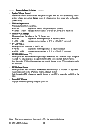
... CPU being installed. (Default: Normal) Note: Increasing CPU voltage may result in damage to set the CPU voltage. Normal sets the CPU voltage as required. GA-M720-US3 Motherboard - 38 - CPU Voltage Control Allows you to your CPU or reduce the useful life of the CPU. Normal Supplies the Northbridge voltage as required...
... CPU being installed. (Default: Normal) Note: Increasing CPU voltage may result in damage to set the CPU voltage. Normal sets the CPU voltage as required. GA-M720-US3 Motherboard - 38 - CPU Voltage Control Allows you to your CPU or reduce the useful life of the CPU. Normal Supplies the Northbridge voltage as required...
Manual
Page 40
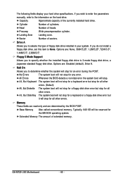
... not install a floppy disk drive, set this item to selects the type of heads. Memory These fields are read-only and are : Disabled (default), Drive A. GA-M720-US3 Motherboard - 40 - Sector Number of cylinders. Drive A Allows you to None. Options are determined by the BIOS POST. No Errors The system boot will stop...
... not install a floppy disk drive, set this item to selects the type of heads. Memory These fields are read-only and are : Disabled (default), Drive A. GA-M720-US3 Motherboard - 40 - Sector Number of cylinders. Drive A Allows you to None. Options are determined by the BIOS POST. No Errors The system boot will stop...
Manual
Page 42
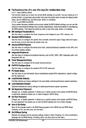
This feature allows your hard drive. Away Mode allows the system to display the GIGABYTE Logo at system startup. PEG Sets the PCI Express graphics card as the first display. Capability Enables or disables the S.M.A.R.T. (Self Monitoring and Reporting ... Mode Enables or disables Away Mode in Windows XP Media Center operating system. PCI Slot Sets the PCI graphics card as the first display. (Default) GA-M720-US3 Motherboard - 42 - Setup A password is only required for entering the BIOS Setup program. (Default) System A password is required for booting the system and ...
This feature allows your hard drive. Away Mode allows the system to display the GIGABYTE Logo at system startup. PEG Sets the PCI Express graphics card as the first display. Capability Enables or disables the S.M.A.R.T. (Self Monitoring and Reporting ... Mode Enables or disables Away Mode in Windows XP Media Center operating system. PCI Slot Sets the PCI graphics card as the first display. (Default) GA-M720-US3 Motherboard - 42 - Setup A password is only required for entering the BIOS Setup program. (Default) System A password is required for booting the system and ...
