Manual
Page 1
GA-M68MT-S2P AM3 socket motherboard for AMD Phenom™ II processor/ AMD Athlon™ II processor User's Manual Rev. 1001 12ME-M68MT2P-1001R
GA-M68MT-S2P AM3 socket motherboard for AMD Phenom™ II processor/ AMD Athlon™ II processor User's Manual Rev. 1001 12ME-M68MT2P-1001R
Manual
Page 2
Motherboard GA-M68MT-S2P Dec. 14, 2009 Motherboard GA-M68MT-S2P Dec. 14, 2009
Motherboard GA-M68MT-S2P Dec. 14, 2009 Motherboard GA-M68MT-S2P Dec. 14, 2009

Manual
Page 3
...detailed product information, carefully read the User's Manual. For instructions on how to use of this product, GIGABYTE provides the following types of the motherboard is the property of this manual are legally registered to assist in this manual may be made by copyright laws and... is 1.0. For product-related information, check on our website at: http://www.gigabyte.com.tw Identifying Your Motherboard Revision The revision number on our website. Example: All rights reserved. Copyright © 2010 GIGA-BYTE TECHNOLOGY CO., LTD....
...detailed product information, carefully read the User's Manual. For instructions on how to use of this product, GIGABYTE provides the following types of the motherboard is the property of this manual are legally registered to assist in this manual may be made by copyright laws and... is 1.0. For product-related information, check on our website at: http://www.gigabyte.com.tw Identifying Your Motherboard Revision The revision number on our website. Example: All rights reserved. Copyright © 2010 GIGA-BYTE TECHNOLOGY CO., LTD....
Manual
Page 4
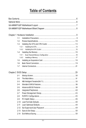
Table of Contents Box Contents...6 Optional Items...6 GA-M68MT-S2P Motherboard Layout 7 GA-M68MT-S2P Motherboard Block Diagram 8 Chapter 1 Hardware Installation 9 1-1 Installation Precautions 9 1-2 Product Specifications 10 1-3 Installing the CPU and CPU Cooler 13 1-3-1 Installing the CPU 13 1-3-2 Installing the CPU Cooler ...
Table of Contents Box Contents...6 Optional Items...6 GA-M68MT-S2P Motherboard Layout 7 GA-M68MT-S2P Motherboard Block Diagram 8 Chapter 1 Hardware Installation 9 1-1 Installation Precautions 9 1-2 Product Specifications 10 1-3 Installing the CPU and CPU Cooler 13 1-3-1 Installing the CPU 13 1-3-2 Installing the CPU Cooler ...
Manual
Page 6
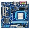
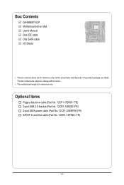
Box Contents GA-M68MT-S2P Motherboard driver disk User's Manual One IDE cable One SATA cable I/O Shield • The box contents above are subject to change without notice. • The motherboard image is for reference only and the actual items shall depend on the product package you obtain. The box contents are for reference only. Optional Items Floppy disk drive cable (Part No. 12CF1-1FD001-7*R) 2-port USB 2.0 bracket (Part No. 12CR1-1UB030-5*R) 2-port SATA power cable (Part No. 12CF1-2SERPW-0*R) S/PDIF In and Out cable (Part No. 12CR1-1SPINO-1*R) - 6 -
Box Contents GA-M68MT-S2P Motherboard driver disk User's Manual One IDE cable One SATA cable I/O Shield • The box contents above are subject to change without notice. • The motherboard image is for reference only and the actual items shall depend on the product package you obtain. The box contents are for reference only. Optional Items Floppy disk drive cable (Part No. 12CF1-1FD001-7*R) 2-port USB 2.0 bracket (Part No. 12CR1-1UB030-5*R) 2-port SATA power cable (Part No. 12CF1-2SERPW-0*R) S/PDIF In and Out cable (Part No. 12CR1-1SPINO-1*R) - 6 -
Manual
Page 8
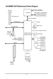
GA-M68MT-S2P Motherboard Block Diagram PCIe CLK (100 MHz) 1 PCI Express x16 AM3 CPU CPU CLK+/- (200 MHz) DDR3 1666(O.C.)/1066/800 MHz Dual Channel Memory Hyper Transport Bus PCI Express x16 1 D-Sub PCI Express Bus 8 USB 2.0/1.1 x1 PCIe CLK (100 MHz) 1 PCI Express x1 LAN RJ45 Realtek RTL8211CL PCI Bus NVIDIA® GeForce 7025/nForce 630a ATA-133/100/66/33 IDE Channel 4 SATA 3Gb/s LPC Bus iTE IT8720 Dual BIOS Floppy COM Port LPT Port CODEC PS/2 KB/Mouse MIC Line Out Line In S/PDIF In S/PDIF Out 2 PCI PCI CLK (33 MHz) - 8 -
GA-M68MT-S2P Motherboard Block Diagram PCIe CLK (100 MHz) 1 PCI Express x16 AM3 CPU CPU CLK+/- (200 MHz) DDR3 1666(O.C.)/1066/800 MHz Dual Channel Memory Hyper Transport Bus PCI Express x16 1 D-Sub PCI Express Bus 8 USB 2.0/1.1 x1 PCIe CLK (100 MHz) 1 PCI Express x1 LAN RJ45 Realtek RTL8211CL PCI Bus NVIDIA® GeForce 7025/nForce 630a ATA-133/100/66/33 IDE Channel 4 SATA 3Gb/s LPC Bus iTE IT8720 Dual BIOS Floppy COM Port LPT Port CODEC PS/2 KB/Mouse MIC Line Out Line In S/PDIF In S/PDIF Out 2 PCI PCI CLK (33 MHz) - 8 -

Manual
Page 9
... the computer system on an uneven surface. • Do not place the computer system in a high-temperature environment. • Turning on the motherboard, make sure the power supply voltage has been set according to the local voltage standard. • Before using the product, please verify that all...of your dealer. These stickers are required for warranty validation. • Always remove the AC power by unplugging the power cord from the motherboard, make sure the power supply has been turned off. • Before turning on the power, make sure they are uncertain about any installation...
... the computer system on an uneven surface. • Do not place the computer system in a high-temperature environment. • Turning on the motherboard, make sure the power supply voltage has been set according to the local voltage standard. • Before using the product, please verify that all...of your dealer. These stickers are required for warranty validation. • Always remove the AC power by unplugging the power cord from the motherboard, make sure the power supply has been turned off. • Before turning on the power, make sure they are uncertain about any installation...

Manual
Page 12
... 3) Whether the CPU fan speed control function is supported will depend on the CPU cooler you install. (Note 4) Available functions in EasyTune may differ by motherboard model. Hardware Installation - 12 -
... 3) Whether the CPU fan speed control function is supported will depend on the CPU cooler you install. (Note 4) Available functions in EasyTune may differ by motherboard model. Hardware Installation - 12 -
Manual
Page 13
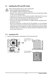
... grease on the surface of the CPU. • Do not turn on the computer if the CPU cooler is not recommended that the motherboard supports the CPU. (Go to GIGABYTE's website for the peripherals. Hardware Installation Locate the pin one of the Socket AM3 Socket A Small Triangle Marking Denotes CPU Pin One...
... grease on the surface of the CPU. • Do not turn on the computer if the CPU cooler is not recommended that the motherboard supports the CPU. (Go to GIGABYTE's website for the peripherals. Hardware Installation Locate the pin one of the Socket AM3 Socket A Small Triangle Marking Denotes CPU Pin One...

Manual
Page 14
... CPU cannot fit in if oriented incorrectly. Adjust the CPU orientation if this occurs. Follow the steps below to correctly install the CPU into the motherboard CPU socket. • Before installing the CPU, make sure to turn off the computer and unplug the power cord from the power outlet to prevent...
... CPU cannot fit in if oriented incorrectly. Adjust the CPU orientation if this occurs. Follow the steps below to correctly install the CPU into the motherboard CPU socket. • Before installing the CPU, make sure to turn off the computer and unplug the power cord from the power outlet to prevent...

Manual
Page 15
...Hardware Installation 1-3-2 Installing the CPU Cooler Follow the steps below to correctly install the CPU cooler on the CPU. (The following procedure uses the GIGABYTE cooler as the picture above shows) to lock into place. (Refer to your CPU cooler installation manual for instructions on installing the cooler.) Step... 5: Finally, attach the power connector of the CPU cooler to the CPU fan header (CPU_FAN) on the motherboard. Step 4: Turn the cam handle from the left side to the right side (as the example.) Step 1: Apply an even and thin layer...
...Hardware Installation 1-3-2 Installing the CPU Cooler Follow the steps below to correctly install the CPU cooler on the CPU. (The following procedure uses the GIGABYTE cooler as the picture above shows) to lock into place. (Refer to your CPU cooler installation manual for instructions on installing the cooler.) Step... 5: Finally, attach the power connector of the CPU cooler to the CPU fan header (CPU_FAN) on the motherboard. Step 4: Turn the cam handle from the left side to the right side (as the example.) Step 1: Apply an even and thin layer...

Manual
Page 16
... is recommended that memory of the same capacity, brand, speed, and chips be installed in Dual Channel mode. 1. It is recommended that the motherboard supports the memory. When enabling Dual Channel mode with two memory modules, it is installed. 2. Hardware Installation - 16 - The two DDR3 memory... are unable to install the memory: • Make sure that memory of the memory. A memory module can be used . (Go to GIGABYTE's website for the latest supported memory speeds and memory modules.) • Always turn off the computer and unplug the power cord from the power...
... is recommended that memory of the same capacity, brand, speed, and chips be installed in Dual Channel mode. 1. It is recommended that the motherboard supports the memory. When enabling Dual Channel mode with two memory modules, it is installed. 2. Hardware Installation - 16 - The two DDR3 memory... are unable to install the memory: • Make sure that memory of the memory. A memory module can be used . (Go to GIGABYTE's website for the latest supported memory speeds and memory modules.) • Always turn off the computer and unplug the power cord from the power...

Manual
Page 17
..., make sure to turn off the computer and unplug the power cord from the power outlet to prevent damage to install DDR3 DIMMs on this motherboard. DDR3 and DDR2 DIMMs are not compatible to each other or DDR DIMMs. Be sure to the memory module. Spread the retaining clips at both...
..., make sure to turn off the computer and unplug the power cord from the power outlet to prevent damage to install DDR3 DIMMs on this motherboard. DDR3 and DDR2 DIMMs are not compatible to each other or DDR DIMMs. Be sure to the memory module. Spread the retaining clips at both...
Manual
Page 18
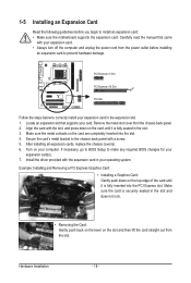
Locate an expansion slot that came with your card. Secure the card's metal bracket to install an expansion card: • Make sure the motherboard supports the expansion card. Hardware Installation - 18 - PCI Express x1 Slot PCI Express x16 Slot PCI Slot Follow the steps below to correctly install your ...
Locate an expansion slot that came with your card. Secure the card's metal bracket to install an expansion card: • Make sure the motherboard supports the expansion card. Hardware Installation - 18 - PCI Express x1 Slot PCI Express x16 Slot PCI Slot Follow the steps below to correctly install your ...

Manual
Page 20
... 2/4/5.1/7.1-Channel Audio." • When removing the cable connected to a back panel connector, first remove the cable from your device and then remove it from the motherboard. • When removing the cable, pull it side to side to prevent an electrical short inside the cable connector. Line Out Jack (Front Speaker Out...
... 2/4/5.1/7.1-Channel Audio." • When removing the cable connected to a back panel connector, first remove the cable from your device and then remove it from the motherboard. • When removing the cable, pull it side to side to prevent an electrical short inside the cable connector. Line Out Jack (Front Speaker Out...

Manual
Page 21
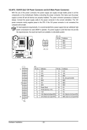
... devices and your devices are compliant with the connectors you wish to connect. • Before installing the devices, be sure to the connector on the motherboard. - 21 - 1-7 Internal Connectors 13 9 13 14 10 11 5 1) ATX_12V 2) ATX 3) CPU_FAN 4) SYS_FAN 5) FDD 6) IDE 7) SATA2_0/1/2/3 2 6 7 8 4 12 8) F_PANEL 9) F_AUDIO 10) CD_IN 11) SPDIF_IO 12) F_USB1/F_USB2...
... devices and your devices are compliant with the connectors you wish to connect. • Before installing the devices, be sure to the connector on the motherboard. - 21 - 1-7 Internal Connectors 13 9 13 14 10 11 5 1) ATX_12V 2) ATX 3) CPU_FAN 4) SYS_FAN 5) FDD 6) IDE 7) SATA2_0/1/2/3 2 6 7 8 4 12 8) F_PANEL 9) F_AUDIO 10) CD_IN 11) SPDIF_IO 12) F_USB1/F_USB2...
Manual
Page 22
..., the result can supply enough stable power to all devices are properly installed. If a power supply is turned off and all the components on the motherboard. The power connector possesses a foolproof design. To meet expansion requirements, it is not connected, the computer will not start.
..., the result can supply enough stable power to all devices are properly installed. If a power supply is turned off and all the components on the motherboard. The power connector possesses a foolproof design. To meet expansion requirements, it is not connected, the computer will not start.

Manual
Page 23
... disk drives supported are not configuration jumper blocks. For purchasing the optional floppy disk drive cable, please contact the local dealer. 33 1 34 2 - 23 - The motherboard supports CPU fan speed control, which requires the use of the connector and the floppy disk drive cable. Definition 1 GND 2 +12V / Speed Control 3 Sense 4 ... connect fan cables to the fan headers to connect a floppy disk drive. Most fan headers possess a foolproof insertion design. 3/4) CPU_FAN/SYS_FAN (Fan Headers) The motherboard has a 4-pin CPU fan header (CPU_FAN) and a 3-pin (SYS_FAN) system fan headers.
... disk drives supported are not configuration jumper blocks. For purchasing the optional floppy disk drive cable, please contact the local dealer. 33 1 34 2 - 23 - The motherboard supports CPU fan speed control, which requires the use of the connector and the floppy disk drive cable. Definition 1 GND 2 +12V / Speed Control 3 Sense 4 ... connect fan cables to the fan headers to connect a floppy disk drive. Most fan headers possess a foolproof insertion design. 3/4) CPU_FAN/SYS_FAN (Fan Headers) The motherboard has a 4-pin CPU fan header (CPU_FAN) and a 3-pin (SYS_FAN) system fan headers.
Manual
Page 26
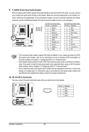
... HD audio by default. Definition 1 CD-L 1 2 GND 3 GND 4 CD-R Hardware Installation - 26 - Incorrect connection between the module connector and the motherboard header will be present on both of the front and back panel audio connections simultaneously. For information about connecting the front panel audio module that... that came with your chassis provides an AC'97 front panel audio module, refer to the instructions on each wire instead of the motherboard header. If you want to mute the back panel audio (only supported when using an HD front panel audio module), refer to...
... HD audio by default. Definition 1 CD-L 1 2 GND 3 GND 4 CD-R Hardware Installation - 26 - Incorrect connection between the module connector and the motherboard header will be present on both of the front and back panel audio connections simultaneously. For information about connecting the front panel audio module that... that came with your chassis provides an AC'97 front panel audio module, refer to the instructions on each wire instead of the motherboard header. If you want to mute the back panel audio (only supported when using an HD front panel audio module), refer to...

Manual
Page 28
... the jumper. Hardware Installation - 28 - 13) CLR_CMOS (Clearing CMOS Jumper) Use this jumper to factory defaults. Failure to do so may cause damage to the motherboard. • After system restart, go to BIOS Setup to load factory defaults (select Load Optimized Defaults) or manually configure the BIOS settings (refer to Chapter...
... the jumper. Hardware Installation - 28 - 13) CLR_CMOS (Clearing CMOS Jumper) Use this jumper to factory defaults. Failure to do so may cause damage to the motherboard. • After system restart, go to BIOS Setup to load factory defaults (select Load Optimized Defaults) or manually configure the BIOS settings (refer to Chapter...


