Manual
Page 1
GA-M68MT-S2 AM3 socket motherboard for AMD Phenom™ II processor/ AMD Athlon™ II processor User's Manual Rev. 1301 12ME-M68MTS2-1301R
GA-M68MT-S2 AM3 socket motherboard for AMD Phenom™ II processor/ AMD Athlon™ II processor User's Manual Rev. 1301 12ME-M68MTS2-1301R
Manual
Page 2
Motherboard GA-M68MT-S2 Nov. 8, 2010 Motherboard GA-M68MT-S2 Nov. 8, 2010
Motherboard GA-M68MT-S2 Nov. 8, 2010 Motherboard GA-M68MT-S2 Nov. 8, 2010
Manual
Page 3
... in this manual may be made by any form or by GIGABYTE without GIGABYTE's prior written permission. In order to their respective owners. For example, "REV: 1.0" means the revision of the motherboard is the property of this product, carefully read the User's Manual.... For product-related information, check on our website at: http://www.gigabyte.com Identifying Your Motherboard Revision The revision number on your motherboard revision before updating motherboard BIOS, drivers, or when looking for technical information. All rights reserved. Changes to the ...
... in this manual may be made by any form or by GIGABYTE without GIGABYTE's prior written permission. In order to their respective owners. For example, "REV: 1.0" means the revision of the motherboard is the property of this product, carefully read the User's Manual.... For product-related information, check on our website at: http://www.gigabyte.com Identifying Your Motherboard Revision The revision number on your motherboard revision before updating motherboard BIOS, drivers, or when looking for technical information. All rights reserved. Changes to the ...
Manual
Page 4
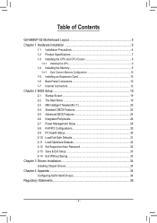
Table of Contents GA-M68MT-S2 Motherboard Layout 5 Chapter 1 Hardware Installation 6 1-1 Installation Precautions 6 1-2 Product Specifications 7 1-3 Installing the CPU and CPU Cooler 9 1-3-1 Installing the CPU...9 1-4 Installing the Memory 9 1-4-1 Dual Channel Memory Configuration 10 1-5 ...
Table of Contents GA-M68MT-S2 Motherboard Layout 5 Chapter 1 Hardware Installation 6 1-1 Installation Precautions 6 1-2 Product Specifications 7 1-3 Installing the CPU and CPU Cooler 9 1-3-1 Installing the CPU...9 1-4 Installing the Memory 9 1-4-1 Dual Channel Memory Configuration 10 1-5 ...
Manual
Page 5
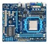
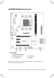
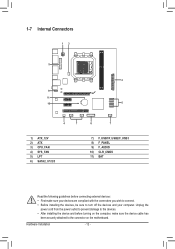
... COMA VGA LPT R_USB CPU_FAN iTE IT8720 LAN USB AUDIO M_BIOS B_BIOS F_AUDIO PCIEX16 Realtek RTL8211CL PCIEX1_1 GA-M68MT-S2 PCIEX1_2 CLR_CMOS BAT NVIDIA® GeForce 7025/nForce 630a PCI CODEC F_PANEL SYS_FAN F_USB3 F_USB2 Box Contents GA-M68MT-S2 motherboard Motherboard driver disk Two SATA cables User's Manual I/O Shield DDR3_1 DDR3_2 ATX SATA2_3 SATA2_2 SATA2_1 SATA2_0 F_USB1...
... COMA VGA LPT R_USB CPU_FAN iTE IT8720 LAN USB AUDIO M_BIOS B_BIOS F_AUDIO PCIEX16 Realtek RTL8211CL PCIEX1_1 GA-M68MT-S2 PCIEX1_2 CLR_CMOS BAT NVIDIA® GeForce 7025/nForce 630a PCI CODEC F_PANEL SYS_FAN F_USB3 F_USB2 Box Contents GA-M68MT-S2 motherboard Motherboard driver disk Two SATA cables User's Manual I/O Shield DDR3_1 DDR3_2 ATX SATA2_3 SATA2_2 SATA2_1 SATA2_0 F_USB1...
Manual
Page 6
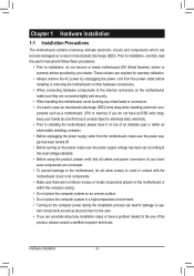
... read the user's manual and follow these procedures: • Prior to installation, do not allow screws to come in contact with the motherboard circuit or its components. • Make sure there are uncertain about any metal leads or connectors. • It is best to wear... an electrostatic discharge (ESD) wrist strap when handling electronic com- These stickers are connected tightly and securely. • When handling the motherboard, avoid touching any installation steps or have it on top of an antistatic pad or within an electrostatic shielding container. • Before ...
... read the user's manual and follow these procedures: • Prior to installation, do not allow screws to come in contact with the motherboard circuit or its components. • Make sure there are uncertain about any metal leads or connectors. • It is best to wear... an electrostatic discharge (ESD) wrist strap when handling electronic com- These stickers are connected tightly and securely. • When handling the motherboard, avoid touching any installation steps or have it on top of an antistatic pad or within an electrostatic shielding container. • Before ...
Manual
Page 8
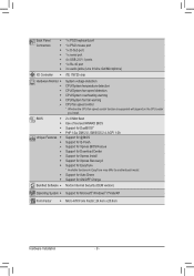
... for Auto Green Support for ON/OFF Charge Norton Internet Security (OEM version) Operating System w Support for EasyTune * Available functions in EasyTune may differ by motherboard model.
... for Auto Green Support for ON/OFF Charge Norton Internet Security (OEM version) Operating System w Support for EasyTune * Available functions in EasyTune may differ by motherboard model.
Manual
Page 9
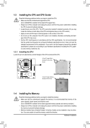
.... • Do not turn on the computer if the CPU cooler is not recommended that the system bus frequency be used. (Go to GIGABYTE's website for the latest CPU support list.) • Always turn off the computer and unplug the power cord from the power outlet before installing...hardware damage. • Memory modules have a foolproof design. If you begin to install the CPU: • Make sure that the motherboard supports the CPU. (Go to GIGABYTE's website for the latest supported memory speeds and memory modules.) • Always turn off the computer and unplug the power cord from ...
.... • Do not turn on the computer if the CPU cooler is not recommended that the system bus frequency be used. (Go to GIGABYTE's website for the latest CPU support list.) • Always turn off the computer and unplug the power cord from the power outlet before installing...hardware damage. • Memory modules have a foolproof design. If you begin to install the CPU: • Make sure that the motherboard supports the CPU. (Go to GIGABYTE's website for the latest supported memory speeds and memory modules.) • Always turn off the computer and unplug the power cord from ...
Manual
Page 10
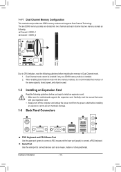
...the following : Channel 0: DDR3_1 Channel 1: DDR3_2 DDR3_1 DDR3_2 Due to install an expansion card: • Make sure the motherboard supports the expansion card. When enabling Dual Channel mode with your expansion card. • Always turn off the computer and ... each channel has two memory sockets as a mouse, modem or other peripherals. Hardware Installation - 10 - 1-4-1 Dual Channel Memory Configuration This motherboard provides two DDR3 memory sockets and supports Dual Channel Technology. Dual Channel mode cannot be used. 1-5 Installing an Expansion Card Read the following ...
...the following : Channel 0: DDR3_1 Channel 1: DDR3_2 DDR3_1 DDR3_2 Due to install an expansion card: • Make sure the motherboard supports the expansion card. When enabling Dual Channel mode with your expansion card. • Always turn off the computer and ... each channel has two memory sockets as a mouse, modem or other peripherals. Hardware Installation - 10 - 1-4-1 Dual Channel Memory Configuration This motherboard provides two DDR3 memory sockets and supports Dual Channel Technology. Dual Channel mode cannot be used. 1-5 Installing an Expansion Card Read the following ...
Manual
Page 11
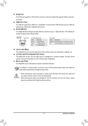
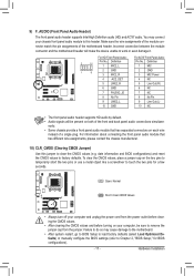
... prevent an electrical short inside the cable connector. - 11 - Microphones must be used to 1 Gbps data rate. Do not rock it straight out from the motherboard. • When removing the cable, pull it side to side to this audio jack for USB devices such as an optical drive, walkman, etc.
... prevent an electrical short inside the cable connector. - 11 - Microphones must be used to 1 Gbps data rate. Do not rock it straight out from the motherboard. • When removing the cable, pull it side to side to this audio jack for USB devices such as an optical drive, walkman, etc.
Manual
Page 12
..., make sure your devices are compliant with the connectors you wish to connect. • Before installing the devices, be sure to the connector on the motherboard.
..., make sure your devices are compliant with the connectors you wish to connect. • Before installing the devices, be sure to the connector on the motherboard.
Manual
Page 13
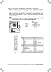
... for 2x12-pin ATX) GND (Only for 2x12-pin ATX) - 13 - If the 12V power connector is turned off and all the components on the motherboard. If a power supply is recommended that a power supply that does not provide the required power, the result can lead to the power connector in the...
... for 2x12-pin ATX) GND (Only for 2x12-pin ATX) - 13 - If the 12V power connector is turned off and all the components on the motherboard. If a power supply is recommended that a power supply that does not provide the required power, the result can lead to the power connector in the...
Manual
Page 14
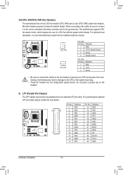
... the optional LPT port cable, please contact the local dealer. When connecting a fan cable, be installed inside the chassis. 1 CPU_FAN 1 SYS_FAN CPU_FAN: Pin No. The motherboard supports CPU fan speed control, which requires the use of a CPU fan with fan speed control design. Definition Pin No. Do not place a jumper cap... (the black connector wire is recommended that a system fan be sure to connect it is the ground wire). DEBUG PORT 3/4) CPU_FAN/SYS_FAN (Fan Headers) The motherboard has a 4-pin CPU fan header (CPU_FAN) and a 3-pin (SYS_FAN) system fan headers.
... the optional LPT port cable, please contact the local dealer. When connecting a fan cable, be installed inside the chassis. 1 CPU_FAN 1 SYS_FAN CPU_FAN: Pin No. The motherboard supports CPU fan speed control, which requires the use of a CPU fan with fan speed control design. Definition Pin No. Do not place a jumper cap... (the black connector wire is recommended that a system fan be sure to connect it is the ground wire). DEBUG PORT 3/4) CPU_FAN/SYS_FAN (Fan Headers) The motherboard has a 4-pin CPU fan header (CPU_FAN) and a 3-pin (SYS_FAN) system fan headers.
Manual
Page 17
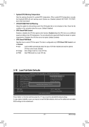
...Values • Always turn off your computer and unplug the power cord from the jumper. Incorrect connection between the module connector and the motherboard header will be sure to remove the jumper cap from the power outlet before clearing the CMOS values. • After clearing the CMOS...to temporarily short the two pins or use a metal object like a screwdriver to clear the CMOS values (e.g. You may cause damage to the motherboard. • After system restart, go to BIOS Setup to load factory defaults (select Load Optimized Defaults) or manually configure the BIOS settings (...
...Values • Always turn off your computer and unplug the power cord from the jumper. Incorrect connection between the module connector and the motherboard header will be sure to remove the jumper cap from the power outlet before clearing the CMOS values. • After clearing the CMOS...to temporarily short the two pins or use a metal object like a screwdriver to clear the CMOS values (e.g. You may cause damage to the motherboard. • After system restart, go to BIOS Setup to load factory defaults (select Load Optimized Defaults) or manually configure the BIOS settings (...
Manual
Page 19
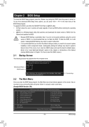
..., it is potentially risky, if you do it with caution. To upgrade the BIOS, use either the GIGABYTE Q-Flash or @BIOS utility. • Q-Flash allows the user to quickly and easily upgrade or back ...the BIOS Setup program, press the key during the POST when the power is recommended that you not flash the BIOS. M68MT-S2 D9 . . . : BIOS Setup : XpressRecovery2 : Boot Menu : Qflash 10/18/2010-NV-MCP68-6A61KG0PC-00 ...Setup program, the Main Menu (as shown below) appears on . Motherboard Model BIOS Version Award Modular BIOS v6.00PG, An Energy Star Ally Copyright (C) 1984-2010, Award Software, ...
..., it is potentially risky, if you do it with caution. To upgrade the BIOS, use either the GIGABYTE Q-Flash or @BIOS utility. • Q-Flash allows the user to quickly and easily upgrade or back ...the BIOS Setup program, press the key during the POST when the power is recommended that you not flash the BIOS. M68MT-S2 D9 . . . : BIOS Setup : XpressRecovery2 : Boot Menu : Qflash 10/18/2010-NV-MCP68-6A61KG0PC-00 ...Setup program, the Main Menu (as shown below) appears on . Motherboard Model BIOS Version Award Modular BIOS v6.00PG, An Energy Star Ally Copyright (C) 1984-2010, Award Software, ...
Manual
Page 30
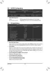
... CMOS, and then restart your system. To clear the chassis intrusion status record, set Reset Case Open Status to Enabled, save the settings to the motherboard CI header. Enabled clears the record of previous chassis intrusion status. Current CPU/SYSTEM FAN Speed (RPM) Displays current CPU/system fan speed. BIOS Setup...
... CMOS, and then restart your system. To clear the chassis intrusion status record, set Reset Case Open Status to Enabled, save the settings to the motherboard CI header. Enabled clears the record of previous chassis intrusion status. Current CPU/SYSTEM FAN Speed (RPM) Displays current CPU/system fan speed. BIOS Setup...
Manual
Page 31
... fan installed and sets the optimal CPU fan control mode. (Default) Voltage Sets Voltage mode for system/CPU temperature. PWM Sets PWM mode for the motherboard. - 31 - If disabled, the CPU fan runs at different speed according to load the safest BIOS default settings. You can adjust the fan speed with...
... fan installed and sets the optimal CPU fan control mode. (Default) Voltage Sets Voltage mode for system/CPU temperature. PWM Sets PWM mode for the motherboard. - 31 - If disabled, the CPU fan runs at different speed according to load the safest BIOS default settings. You can adjust the fan speed with...
Manual
Page 34
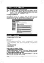
... Chapter 3 Drivers Installation • Before installing the drivers, first install the operating system. • After installing the operating system, insert the motherboard driver disk into your power supply to the hard drive. You can click the Install All button and "Xpress Install" will automatically scan your ...computer Attach one hard drive. • An empty formatted floppy disk. • Windows Vista/XP setup disk. • Motherboard driver disk. Or click Install Single Items to manually select the drivers you may prepare only one end of the SATA signal cable to ...
... Chapter 3 Drivers Installation • Before installing the drivers, first install the operating system. • After installing the operating system, insert the motherboard driver disk into your power supply to the hard drive. You can click the Install All button and "Xpress Install" will automatically scan your ...computer Attach one hard drive. • An empty formatted floppy disk. • Windows Vista/XP setup disk. • Motherboard driver disk. Or click Install Single Items to manually select the drivers you may prepare only one end of the SATA signal cable to ...
Manual
Page 35
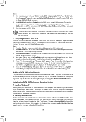
...SATA RAID Driver Diskette Copy the driver for your system to boot from field to the Array Disks block. 5. Installing Windows 7/Vista Restart your motherboard. For Windows 7, browse to BootDrv\UDA\Win7\sataraid to enter the NVIDIA RAID setup utility. Configuring RAID set in the Array List screen....you see shall depend on your floppy disk: BootDrv\UDA\WinXP\sataraid Installing the SATA RAID Driver and Operating System A. Turn on the motherboard you can be set the striping block size. Select Load Driver. Then enable the SATA channels with the Windows XP installation. Steps:...
...SATA RAID Driver Diskette Copy the driver for your system to boot from field to the Array Disks block. 5. Installing Windows 7/Vista Restart your motherboard. For Windows 7, browse to BootDrv\UDA\Win7\sataraid to enter the NVIDIA RAID setup utility. Configuring RAID set in the Array List screen....you see shall depend on your floppy disk: BootDrv\UDA\WinXP\sataraid Installing the SATA RAID Driver and Operating System A. Turn on the motherboard you can be set the striping block size. Select Load Driver. Then enable the SATA channels with the Windows XP installation. Steps:...
Manual
Page 36
.... To prevent releases of harmful substances into the environment and to maximize the use of Hazardous Substances (RoHS) Directive Statement GIGABYTE products have been carefully selected to a third party nor be marked, collected separately, and disposed of environmentally safe recycling....and should be prosecuted. Also note that the information in a manner that the information contained herein was accurate in all GIGABYTE motherboards fulfill European Union regulations for errors or omissions in Electrical and Electronic Equipment) and WEEE (Waste Electrical and Electronic Equipment)...
.... To prevent releases of harmful substances into the environment and to maximize the use of Hazardous Substances (RoHS) Directive Statement GIGABYTE products have been carefully selected to a third party nor be marked, collected separately, and disposed of environmentally safe recycling....and should be prosecuted. Also note that the information in a manner that the information contained herein was accurate in all GIGABYTE motherboards fulfill European Union regulations for errors or omissions in Electrical and Electronic Equipment) and WEEE (Waste Electrical and Electronic Equipment)...


