Manual
Page 4
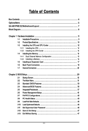
Table of Contents Box Contents ...6 OptionalItems...6 GA-M61PME-S2 Motherboard Layout 7 Block Diagram...8 Chapter 1 Hardware Installation 9 1-1 Installation Precautions 9 1-2 Product Specifications 10 1-3 Installing the CPU and CPU Cooler 12 1-3-1 Installing the CPU 12 1-3-2 Installing the CPU Cooler 14 1-4 Installing the Memory 15 1-4-1 Dual Channel Memory Configuration 15 1-4-2 Installing a Memory 16 1-5 Installing an Expansion Card 17 1-6 Back Panel Connectors 18...
Table of Contents Box Contents ...6 OptionalItems...6 GA-M61PME-S2 Motherboard Layout 7 Block Diagram...8 Chapter 1 Hardware Installation 9 1-1 Installation Precautions 9 1-2 Product Specifications 10 1-3 Installing the CPU and CPU Cooler 12 1-3-1 Installing the CPU 12 1-3-2 Installing the CPU Cooler 14 1-4 Installing the Memory 15 1-4-1 Dual Channel Memory Configuration 15 1-4-2 Installing a Memory 16 1-5 Installing an Expansion Card 17 1-6 Back Panel Connectors 18...
Manual
Page 8
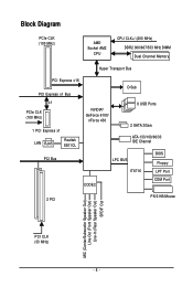
Block Diagram PCIe CLK (100 MHz) AMD Socket AM2 CPU CPU CLK+/-(200 MHz) DDR2 800/667/533 MHz DIMM Dual Channel Memory Hyper Transport Bus PCI Express x16 PCI Express x1 Bus D-Sub x1 PCIe CLK (100 MHz) 1 PCI Express x1 LAN RJ45 Realtek 8201CL NVIDIA® GeForce 6100/ nForce 430 8 USB Ports 2 SATA 3Gb/s ATA-133/100/66/33 IDE Channel PCI Bus LPC BUS BIOS Floppy IT8716 LPT Port CODEC COM Port 2 PCI PS/2 KB/Mouse MIC (Center/Subwoofer Speaker Out) Line-Out (Front Speaker Out) Line-In (Rear Speaker Out) SPDIF Out PCI CLK (33 MHz) - 8 -
Block Diagram PCIe CLK (100 MHz) AMD Socket AM2 CPU CPU CLK+/-(200 MHz) DDR2 800/667/533 MHz DIMM Dual Channel Memory Hyper Transport Bus PCI Express x16 PCI Express x1 Bus D-Sub x1 PCIe CLK (100 MHz) 1 PCI Express x1 LAN RJ45 Realtek 8201CL NVIDIA® GeForce 6100/ nForce 430 8 USB Ports 2 SATA 3Gb/s ATA-133/100/66/33 IDE Channel PCI Bus LPC BUS BIOS Floppy IT8716 LPT Port CODEC COM Port 2 PCI PS/2 KB/Mouse MIC (Center/Subwoofer Speaker Out) Line-Out (Front Speaker Out) Line-In (Rear Speaker Out) SPDIF Out PCI CLK (33 MHz) - 8 -
Manual
Page 9
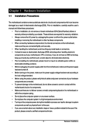
... touching any installation steps or have a problem related to the internal connectors on the computer power during the installation process can become damaged as a motherboard, CPU or memory. If you do not remove or break motherboard S/N (Serial Number) sticker or warranty sticker provided by unplugging the power cord from the motherboard...
... touching any installation steps or have a problem related to the internal connectors on the computer power during the installation process can become damaged as a motherboard, CPU or memory. If you do not remove or break motherboard S/N (Serial Number) sticker or warranty sticker provided by unplugging the power cord from the motherboard...
Manual
Page 10
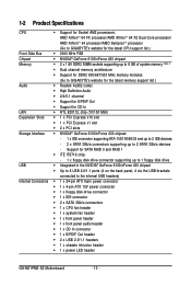
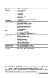
...processor/AMD AthlonTM 64 X2 Dual-Core processor/ AMD AthlonTM 64 processor/AMD SempronTM processor (Go to GIGABYTE's website for the latest CPU support list.) Front Side Bus 2000 MHz FSB Chipset NVIDIA® GeForce ...x SATA 3Gb/s connectors 1 x CPU fan header 1 x system fan header 1 x front panel header 1 x front panel audio header 1 x CD In connector 1 x S/PDIF Out header 2 x USB 2.0/1.1 headers 1 x chassis intrusion header 1 x power LED header GA-M61PME-S2 Motherboard - 10 -
...processor/AMD AthlonTM 64 X2 Dual-Core processor/ AMD AthlonTM 64 processor/AMD SempronTM processor (Go to GIGABYTE's website for the latest CPU support list.) Front Side Bus 2000 MHz FSB Chipset NVIDIA® GeForce ...x SATA 3Gb/s connectors 1 x CPU fan header 1 x system fan header 1 x front panel header 1 x front panel audio header 1 x CD In connector 1 x S/PDIF Out header 2 x USB 2.0/1.1 headers 1 x chassis intrusion header 1 x power LED header GA-M61PME-S2 Motherboard - 10 -
Manual
Page 11
... In/Line Out/Microphone) iTE IT8716 chip System voltage detection CPU/System temperature detection CPU/System fan speed detection CPU/System overheating warning CPU/System fan fail warning CPU fan speed control (Note 2) 1 x 4 Mbit flash Use of licensed... is installed, the actual memory size displayed will be less than 4 GB. (Note 2) Whether the CPU fan speed control function is supported will depend on the CPU you install. (Note 3) Available functions in Easytune may differ by motherboard model. - 11 - Hardware ...
... In/Line Out/Microphone) iTE IT8716 chip System voltage detection CPU/System temperature detection CPU/System fan speed detection CPU/System overheating warning CPU/System fan fail warning CPU fan speed control (Note 2) 1 x 4 Mbit flash Use of licensed... is installed, the actual memory size displayed will be less than 4 GB. (Note 2) Whether the CPU fan speed control function is supported will depend on the CPU you install. (Note 3) Available functions in Easytune may differ by motherboard model. - 11 - Hardware ...

Manual
Page 12
...8226; Locate the pin one (denoted by a small triangle) of the CPU. mended that the motherboard supports the CPU. (Go to GIGABYTE's website for the peripherals. 1-3 Installing the CPU and CPU Cooler Read the following guidelines before you wish to set beyond the standard ...do so according to your hardware specifications including the CPU, graphics card, memory, hard drive, etc. 1-3-1 Installing the CPU A. It is not installed, otherwise overheating and damage of the Socket AM2 CPU Socket A Small Triangle Marking Denotes CPU Pin One AM2 CPU GA-M61PME-S2 Motherboard - 12 -
...8226; Locate the pin one (denoted by a small triangle) of the CPU. mended that the motherboard supports the CPU. (Go to GIGABYTE's website for the peripherals. 1-3 Installing the CPU and CPU Cooler Read the following guidelines before you wish to set beyond the standard ...do so according to your hardware specifications including the CPU, graphics card, memory, hard drive, etc. 1-3-1 Installing the CPU A. It is not installed, otherwise overheating and damage of the Socket AM2 CPU Socket A Small Triangle Marking Denotes CPU Pin One AM2 CPU GA-M61PME-S2 Motherboard - 12 -

Manual
Page 13
... the power outlet to prevent damage to correctly install the CPU into the motherboard CPU socket. Step 2: Align the CPU pin one finger down on the CPU socket and gently insert the CPU into the fully locked position. Once the CPU is positioned into its socket, place one (small triangle marking...) with the triangle mark on the middle of the CPU, lowering the locking lever and latching it into the socket. B. CPU Socket Locking Lever Step 1: Completely lift up the CPU socket locking lever. Adjust the CPU orientation if this occurs. - 13 - Make sure that the...
... the power outlet to prevent damage to correctly install the CPU into the motherboard CPU socket. Step 2: Align the CPU pin one finger down on the CPU socket and gently insert the CPU into the fully locked position. Once the CPU is positioned into its socket, place one (small triangle marking...) with the triangle mark on the middle of the CPU, lowering the locking lever and latching it into the socket. B. CPU Socket Locking Lever Step 1: Completely lift up the CPU socket locking lever. Adjust the CPU orientation if this occurs. - 13 - Make sure that the...

Manual
Page 14
... thermal grease on the motherboard. GA-M61PME-S2 Motherboard - 14 - Use extreme care when removing the CPU cooler because the thermal grease/tape between the CPU cooler and CPU may damage the CPU. 1-3-2 Installing the CPU Cooler Follow the steps below to correctly install the CPU cooler on the CPU. (The following procedure uses the GIGABYTE cooler as the picture above...
... thermal grease on the motherboard. GA-M61PME-S2 Motherboard - 14 - Use extreme care when removing the CPU cooler because the thermal grease/tape between the CPU cooler and CPU may damage the CPU. 1-3-2 Installing the CPU Cooler Follow the steps below to correctly install the CPU cooler on the CPU. (The following procedure uses the GIGABYTE cooler as the picture above...
Manual
Page 15
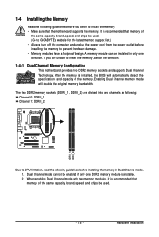
...be installed in Dual Channel mode. 1. If you are divided into two channels as following: Channel 0: DDRII_1 Channel 1: DDRII_2 DDRII_1 DDRII_2 Due to CPU limitation, read the following guidelines before you begin to prevent hardware damage. • Memory modules have a foolproof design. 1-4 Installing the Memory Read...in only one DDR2 memory module is recommended that memory of the same capacity, brand, speed, and chips be used. (Go to GIGABYTE's website for the latest memory support list.) • Always turn off the computer and unplug the power cord from the power outlet before...
...be installed in Dual Channel mode. 1. If you are divided into two channels as following: Channel 0: DDRII_1 Channel 1: DDRII_2 DDRII_1 DDRII_2 Due to CPU limitation, read the following guidelines before you begin to prevent hardware damage. • Memory modules have a foolproof design. 1-4 Installing the Memory Read...in only one DDR2 memory module is recommended that memory of the same capacity, brand, speed, and chips be used. (Go to GIGABYTE's website for the latest memory support list.) • Always turn off the computer and unplug the power cord from the power outlet before...
Manual
Page 21
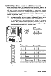
...) GND GND GND -5V +5V +5V +5V (Only for 2x12-pinATX) GND (Only for 2x12-pin ATX) - 21 - Connect the power supply cable to the CPU. Do not insert the power supply cable into pins under the protective cover when using a 2x12 power supply, remove the protective cover from the main...
...) GND GND GND -5V +5V +5V +5V (Only for 2x12-pinATX) GND (Only for 2x12-pin ATX) - 21 - Connect the power supply cable to the CPU. Do not insert the power supply cable into pins under the protective cover when using a 2x12 power supply, remove the protective cover from the main...
Manual
Page 22
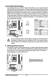
... in damage to locate pin 1 of the connector and the floppy disk drive cable. The pin 1 of different color. 33 1 34 2 GA-M61PME-S2 Motherboard - 22 - A red power connector wire indicates a positive connection and requires a +12V voltage. The black connector wire is typically designated by a... in the correct orientation. Before connecting a floppy disk drive, be installed inside the chassis. 3/4) CPU_FAN/SYS_FAN (Fan Headers) The motherboard has a 4-pin CPU fan header (CPU_FAN) and a 3-pin system fan header (SYS_FAN). Most fans are : 360 KB, 720 KB, 1.2 MB, 1.44 MB, and ...
... in damage to locate pin 1 of the connector and the floppy disk drive cable. The pin 1 of different color. 33 1 34 2 GA-M61PME-S2 Motherboard - 22 - A red power connector wire indicates a positive connection and requires a +12V voltage. The black connector wire is typically designated by a... in the correct orientation. Before connecting a floppy disk drive, be installed inside the chassis. 3/4) CPU_FAN/SYS_FAN (Fan Headers) The motherboard has a 4-pin CPU fan header (CPU_FAN) and a 3-pin system fan header (SYS_FAN). Most fans are : 360 KB, 720 KB, 1.2 MB, 1.44 MB, and ...
Manual
Page 32
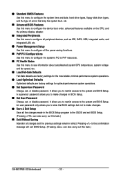
.... PnP/PCI Configurations Use this menu to configure the system's PCI & PnP resources. PC Health Status Use this task.) GA-M61PME-S2 Motherboard - 32 - A supervisor password allows you to view the BIOS settings but not to make changes in effect. An user password only allows...stop the system boot, etc. Advanced BIOS Features Use this menu to configure the device boot order, advanced features available on the CPU, and the primary display adapter. Integrated Peripherals Use this menu to configure all peripheral devices, such as IDE, SATA, USB, ...
.... PnP/PCI Configurations Use this menu to configure the system's PCI & PnP resources. PC Health Status Use this task.) GA-M61PME-S2 Motherboard - 32 - A supervisor password allows you to view the BIOS settings but not to make changes in effect. An user password only allows...stop the system boot, etc. Advanced BIOS Features Use this menu to configure the device boot order, advanced features available on the CPU, and the primary display adapter. Integrated Peripherals Use this menu to configure all peripheral devices, such as IDE, SATA, USB, ...

Manual
Page 35
... computer system can function as multiple virtual systems. (Default: Disabled) AMD K8 Cool&Quiet control Auto Lets the AMD Cool'n'Quiet driver dynamically adjust the CPU clock and VIA to move it up or down on the list. Capability Away Mode Init Display First Frame Buffer Size Onboard GPU [Disabled] [Auto...
... computer system can function as multiple virtual systems. (Default: Disabled) AMD K8 Cool&Quiet control Auto Lets the AMD Cool'n'Quiet driver dynamically adjust the CPU clock and VIA to move it up or down on the list. Capability Away Mode Init Display First Frame Buffer Size Onboard GPU [Disabled] [Auto...
Manual
Page 43
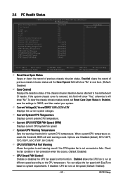
... cover is not connected or fails. Current Voltage(V) Vcore/DDR2 1.8V/+3.3V/+12V Displays the current system voltages. If disabled, CPU fan runs at next boot. (Default: Disabled) Case Opened Displays the detection status of the chassis intrusion detection device attached to... To clear the chassis intrusion status record, set Reset Case Open Status to Enabled, save the settings to the CPU temperature. Current System/CPU Temperature Displays current system/CPU temperature. You can adjust the fan speed with EasyTune based on system requirements. BIOS Setup Options are: Disabled (default...
... cover is not connected or fails. Current Voltage(V) Vcore/DDR2 1.8V/+3.3V/+12V Displays the current system voltages. If disabled, CPU fan runs at next boot. (Default: Disabled) Case Opened Displays the detection status of the chassis intrusion detection device attached to... To clear the chassis intrusion status record, set Reset Case Open Status to Enabled, save the settings to the CPU temperature. Current System/CPU Temperature Displays current system/CPU temperature. You can adjust the fan speed with EasyTune based on system requirements. BIOS Setup Options are: Disabled (default...
Manual
Page 44
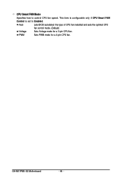
GA-M61PME-S2 Motherboard - 44 - CPU Smart FAN Mode Specifies how to Enabled. This item is configurable only if CPU Smart FAN Control is set to control CPU fan speed. PWM Sets PWM mode for a 3-pin CPU fan. Auto Lets BIOS autodetect the type of CPU fan installed and sets the optimal CPU fan control mode. (Default) Voltage Sets Voltage mode for a 4-pin CPU fan.
GA-M61PME-S2 Motherboard - 44 - CPU Smart FAN Mode Specifies how to Enabled. This item is configurable only if CPU Smart FAN Control is set to control CPU fan speed. PWM Sets PWM mode for a 3-pin CPU fan. Auto Lets BIOS autodetect the type of CPU fan installed and sets the optimal CPU fan control mode. (Default) Voltage Sets Voltage mode for a 4-pin CPU fan.
Manual
Page 63
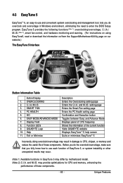
...page Confirmation and Execution button Toggles between Easy and Advance Mode Displays panel of CPU frequency Shows the information of the current function Visits GIGABYTE website Displays EasyTuneTM 5 help screen Quits or minimizes EasyTuneTM 5 Incorrectly doing overclock...lets you do the overclock/overvoltage, make sure that you do overclock and overvoltage in EasyTune 5 may provide optimizations for CPU and memory, enhancing the performance of these components. GIGABYTE Logo 10. and M.I .B. 3. Function LEDs 9. SMART FAN 4. may differ by motherboard model. (Note 2) C.I...
...page Confirmation and Execution button Toggles between Easy and Advance Mode Displays panel of CPU frequency Shows the information of the current function Visits GIGABYTE website Displays EasyTuneTM 5 help screen Quits or minimizes EasyTuneTM 5 Incorrectly doing overclock...lets you do the overclock/overvoltage, make sure that you do overclock and overvoltage in EasyTune 5 may provide optimizations for CPU and memory, enhancing the performance of these components. GIGABYTE Logo 10. and M.I .B. 3. Function LEDs 9. SMART FAN 4. may differ by motherboard model. (Note 2) C.I...

Manual
Page 83
...the memory slot. The problem is verified and solved. START Turn off the power. Yes Check if the memory is installed properly on the CPU. The problem is verified and solved. The problem is attached to start the computer. Select "Save & Exit Setup" to the CPU_FAN header... Defaults"). Yes Isolate the short circuit. Make sure the motherboard does not short-circuit with the chassis or other metal objects. Connect the CPU cooler power cable to the motherboard. Appendix Remove all peripherals, connecting cables, and power cord etc. Connect the ATX main power cable and...
...the memory slot. The problem is verified and solved. START Turn off the power. Yes Check if the memory is installed properly on the CPU. The problem is verified and solved. The problem is attached to start the computer. Select "Save & Exit Setup" to the CPU_FAN header... Defaults"). Yes Isolate the short circuit. Make sure the motherboard does not short-circuit with the chassis or other metal objects. Connect the CPU cooler power cable to the motherboard. Appendix Remove all peripherals, connecting cables, and power cord etc. Connect the ATX main power cable and...

Manual
Page 84
.... No The keyboard or mouse might fail. Our customer service staff will reply you as soon as possible. GA-M61PME-S2 Motherboard - 84 - Yes Check if there is display on , is the CPU cooler running? Select "Load Fail-Safe Defaults" (or "Load Optimized Defaults"). No The IDE/SATA device, connector..., or cable might fail. Yes Turn off the computer and connect the IDE/SATA devices. No The power supply, CPU or CPU socket might fail. Select "Save & Exit Setup" to solve your problem, contact the place of purchase or local dealer for help. Check ...
.... No The keyboard or mouse might fail. Our customer service staff will reply you as soon as possible. GA-M61PME-S2 Motherboard - 84 - Yes Check if there is display on , is the CPU cooler running? Select "Load Fail-Safe Defaults" (or "Load Optimized Defaults"). No The IDE/SATA device, connector..., or cable might fail. Yes Turn off the computer and connect the IDE/SATA devices. No The power supply, CPU or CPU socket might fail. Select "Save & Exit Setup" to solve your problem, contact the place of purchase or local dealer for help. Check ...


