Manual
Page 1
GA-M61PM-S2 (rev. 2.0) AMD Socket AM2 Processor Motherboard User's Manual Rev. 2002 12ME-M61PMS2-2002R * The WEEE marking on the product indicates this product must not be disposed of with user's other household waste and must be handed over to a designated collection point for the recycling of waste electrical and electronic equipment!! * The WEEE marking applies only in European Union's member states.
GA-M61PM-S2 (rev. 2.0) AMD Socket AM2 Processor Motherboard User's Manual Rev. 2002 12ME-M61PMS2-2002R * The WEEE marking on the product indicates this product must not be disposed of with user's other household waste and must be handed over to a designated collection point for the recycling of waste electrical and electronic equipment!! * The WEEE marking applies only in European Union's member states.

Manual
Page 2
Motherboard GA-M61PM-S2 (rev. 2.0) Nov. 29, 2006 Motherboard GA-M61PM-S2 (rev. 2.0) Nov. 29, 2006
Motherboard GA-M61PM-S2 (rev. 2.0) Nov. 29, 2006 Motherboard GA-M61PM-S2 (rev. 2.0) Nov. 29, 2006
Manual
Page 4
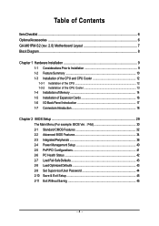
Table of Contents ItemChecklist ...6 OptionalAccessories ...6 GA-M61PM-S2 (rev. 2.0) Motherboard Layout 7 Block Diagram ...8 Chapter 1 Hardware Installation 9 1-1 Considerations Prior to Installation 9 1-2 Feature Summary 10 1-3 Installation of the CPU and CPU Cooler 12 1-3-1 Installation of the ...
Table of Contents ItemChecklist ...6 OptionalAccessories ...6 GA-M61PM-S2 (rev. 2.0) Motherboard Layout 7 Block Diagram ...8 Chapter 1 Hardware Installation 9 1-1 Considerations Prior to Installation 9 1-2 Feature Summary 10 1-3 Installation of the CPU and CPU Cooler 12 1-3-1 Installation of the ...
Manual
Page 7
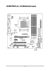
GA-M61PM-S2 (rev. 2.0) Motherboard Layout VGA COMA LPT USB USB 1394 LAN KB_MS ATX_12V Socket AM2 ATX CPU_FAN IT8716 AUDIO F_AUDIO BIOS CI PCIE_16 GA-M61PM-S2 RTL8211 PCIE_1 PCI1 CD_IN PCI2 CODEC REV: 2.0 SPDIF_IO COMB CLR_CMOS BATTERY nVIDIA® GeForce 6100/ nForce 430 TSB43AB23 F1_1394 F2_1394 SYS_FAN IDE FDD F_USB2 F_USB1 F_USB3 F_PANEL PWR_LED DDRII_1 DDRII_2 DDRII_3 DDRII_4 SATAII1 SATAII3 SATAII0 SATAII2 - 7 -
GA-M61PM-S2 (rev. 2.0) Motherboard Layout VGA COMA LPT USB USB 1394 LAN KB_MS ATX_12V Socket AM2 ATX CPU_FAN IT8716 AUDIO F_AUDIO BIOS CI PCIE_16 GA-M61PM-S2 RTL8211 PCIE_1 PCI1 CD_IN PCI2 CODEC REV: 2.0 SPDIF_IO COMB CLR_CMOS BATTERY nVIDIA® GeForce 6100/ nForce 430 TSB43AB23 F1_1394 F2_1394 SYS_FAN IDE FDD F_USB2 F_USB1 F_USB3 F_PANEL PWR_LED DDRII_1 DDRII_2 DDRII_3 DDRII_4 SATAII1 SATAII3 SATAII0 SATAII2 - 7 -

Manual
Page 10
... Š Onboard T.I. English 1-2 Feature Summary CPU Š Socket AM2 for additional 2 ports by cable Š 1 COMB connector Š 1 power LED connector Š 1 Chassis Intrusion connector GA-M61PM-S2 (rev. 2.0) Motherboard - 10 -
... Š Onboard T.I. English 1-2 Feature Summary CPU Š Socket AM2 for additional 2 ports by cable Š 1 COMB connector Š 1 power LED connector Š 1 Chassis Intrusion connector GA-M61PM-S2 (rev. 2.0) Motherboard - 10 -
Manual
Page 12
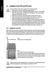
... CPU. Align the CPU to system use extra care when installing the CPU. Please use , otherwise overheating and permanent damage of the CPU may occur. 5. GA-M61PM-S2 (rev. 2.0) Motherboard - 12 - English 1-3 Installation of the CPU and CPU Cooler Before installing the CPU, please comply with the processor specifications. If you wish to set...
... CPU. Align the CPU to system use extra care when installing the CPU. Please use , otherwise overheating and permanent damage of the CPU may occur. 5. GA-M61PM-S2 (rev. 2.0) Motherboard - 12 - English 1-3 Installation of the CPU and CPU Cooler Before installing the CPU, please comply with the processor specifications. If you wish to set...

Manual
Page 14
... Fig.1 The DIMM socket has a notch, so the DIMM memory module can differ with the following conditions: 1. A memory module can be installed in one direction. GA-M61PM-S2 (rev. 2.0) Motherboard - 14 - It is switched off to remove the DIMM module. Before installing or removing memory modules, please make sure that the computer power is...
... Fig.1 The DIMM socket has a notch, so the DIMM memory module can differ with the following conditions: 1. A memory module can be installed in one direction. GA-M61PM-S2 (rev. 2.0) Motherboard - 14 - It is switched off to remove the DIMM module. Before installing or removing memory modules, please make sure that the computer power is...

Manual
Page 16
... of the expansion card. 6. Press the expansion card firmly into the computer. 2. Replace your computer's chassis cover, screws and slot bracket from the operating system. GA-M61PM-S2 (rev. 2.0) Motherboard - 16 - Replace the screw to secure the slot bracket of the PCI Express x16 slot. Remove your computer's chassis cover. 7. Installing a PCI Express x16...
... of the expansion card. 6. Press the expansion card firmly into the computer. 2. Replace your computer's chassis cover, screws and slot bracket from the operating system. GA-M61PM-S2 (rev. 2.0) Motherboard - 16 - Replace the screw to secure the slot bracket of the PCI Express x16 slot. Remove your computer's chassis cover. 7. Installing a PCI Express x16...
Manual
Page 18
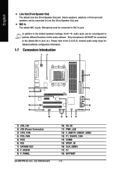
... steps for detailed software configuration information. 1-7 Connectors Introduction 13 6 2 17 8 16 10 15 14 1) ATX_12V 2) ATX (Power Connector) 3) CPU_FAN 4) SYS_FAN 5) FDD 6) IDE 7) SATAII0/1/2/3 8) F_AUDIO 9) F_PANEL GA-M61PM-S2 (rev. 2.0) Motherboard 5 7 12 9 13 18 4 11 10) CD_IN 11) PWR_LED 12) F_USB1/F_USB2/F_USB3 13) F1_1394/F2_1394 14) COMB 15) SPDIF_IO 16) CLR_CMOS 17) CI 18...
... steps for detailed software configuration information. 1-7 Connectors Introduction 13 6 2 17 8 16 10 15 14 1) ATX_12V 2) ATX (Power Connector) 3) CPU_FAN 4) SYS_FAN 5) FDD 6) IDE 7) SATAII0/1/2/3 8) F_AUDIO 9) F_PANEL GA-M61PM-S2 (rev. 2.0) Motherboard 5 7 12 9 13 18 4 11 10) CD_IN 11) PWR_LED 12) F_USB1/F_USB2/F_USB3 13) F1_1394/F2_1394 14) COMB 15) SPDIF_IO 16) CLR_CMOS 17) CI 18...
Manual
Page 20
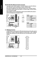
... +12V Sense 5) FDD (Floppy Connector) The FDD connector is the ground wire (GND). The types of the foolproof groove in the FDD connector. 34 33 2 1 GA-M61PM-S2 (rev. 2.0) Motherboard - 20 - English 3/4) CPU_FAN / SYS_FAN (Cooler Fan Power Connector) The cooler fan power connector supplies a +12V power voltage via a 3-pin (SYS_FAN)/4-pin (CPU_FAN) power connector...
... +12V Sense 5) FDD (Floppy Connector) The FDD connector is the ground wire (GND). The types of the foolproof groove in the FDD connector. 34 33 2 1 GA-M61PM-S2 (rev. 2.0) Motherboard - 20 - English 3/4) CPU_FAN / SYS_FAN (Cooler Fan Power Connector) The cooler fan power connector supplies a +12V power voltage via a 3-pin (SYS_FAN)/4-pin (CPU_FAN) power connector...
Manual
Page 22
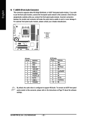
... 8) F_AUDIO (Front Audio Connector) This connector supports either HD (High Definition) or AC97 front panel audio module. If you connect the front panel audio module. GA-M61PM-S2 (rev. 2.0) Motherboard - 22 - Check the pin assignments carefully while you wish to use the front audio function, connect the front panel audio module to this connector...
... 8) F_AUDIO (Front Audio Connector) This connector supports either HD (High Definition) or AC97 front panel audio module. If you connect the front panel audio module. GA-M61PM-S2 (rev. 2.0) Motherboard - 22 - Check the pin assignments carefully while you wish to use the front audio function, connect the front panel audio module to this connector...

Manual
Page 24
Definition 1 CD-L 1 2 GND 3 GND 4 CD-R 11) PWR_LED The PWR_LED connector is connected with the system power indicator to the connector. Definition 1 MPD+ 2 MPD- 1 3 MPD- Pin No. GA-M61PM-S2 (rev. 2.0) Motherboard - 24 - It will blink when the system enters suspend mode (S1). English 10) CD_IN (CD In Connector) Connect CD-ROM or DVD-ROM audio out to indicate whether the system is on/off. Pin No.
Definition 1 CD-L 1 2 GND 3 GND 4 CD-R 11) PWR_LED The PWR_LED connector is connected with the system power indicator to the connector. Definition 1 MPD+ 2 MPD- 1 3 MPD- Pin No. GA-M61PM-S2 (rev. 2.0) Motherboard - 24 - It will blink when the system enters suspend mode (S1). English 10) CD_IN (CD In Connector) Connect CD-ROM or DVD-ROM audio out to indicate whether the system is on/off. Pin No.
Manual
Page 26
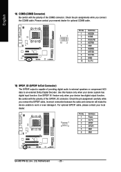
... cable. Be careful with the polarity of the COMB connector. Please contact your local dealer. 5 1 6 2 Pin No. 1 2 3 4 5 6 Definition Power No Pin SPDIF SPDIFI GND GND GA-M61PM-S2 (rev. 2.0) Motherboard - 26 - English 14) COMB (COMB Connector) Be careful with the polarity of the S/PDIF_IO connector. For optional S/PDIF cable, please contact your nearest dealer...
... cable. Be careful with the polarity of the COMB connector. Please contact your local dealer. 5 1 6 2 Pin No. 1 2 3 4 5 6 Definition Power No Pin SPDIF SPDIFI GND GND GA-M61PM-S2 (rev. 2.0) Motherboard - 26 - English 14) COMB (COMB Connector) Be careful with the polarity of the S/PDIF_IO connector. For optional S/PDIF cable, please contact your nearest dealer...
Manual
Page 28
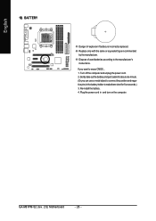
Turn off the computer and unplug the power cord. 2. Re-install the battery. 4. If you can use a metal object to erase CMOS... 1. GA-M61PM-S2 (rev. 2.0) Motherboard - 28 - Gently take out the battery and put it aside for about one minute. (Or you want to connect the positive and negative pins ...
Turn off the computer and unplug the power cord. 2. Re-install the battery. 4. If you can use a metal object to erase CMOS... 1. GA-M61PM-S2 (rev. 2.0) Motherboard - 28 - Gently take out the battery and put it aside for about one minute. (Or you want to connect the positive and negative pins ...
Manual
Page 30
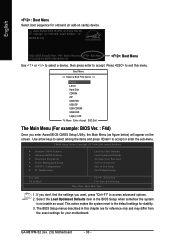
...the settings you enter Award BIOS CMOS Setup Utility, the Main Menu (as usual. Select the Load Optimized Defaults item in this menu. GA-M61PM-S2 (rev. 2.0) Motherboard - 30 - This action makes the system reset to exit this chapter are for reference only and may differ from the ... to accept. English : Boot Menu Select boot sequence for stability. 3. Award Modular BIOS v6.00PG, An Energy Star Ally Copyright (C) 1984-2006, Award Software, Inc. M61PM-S2 F4d . . . . :BIOS Setup/Q-Flash, : Xpress Recovery2, : Boot Menu 11/22/2006-NV-MCP61-6A61KG02C-00 : Boot Menu Use < > or < > ...
...the settings you enter Award BIOS CMOS Setup Utility, the Main Menu (as usual. Select the Load Optimized Defaults item in this menu. GA-M61PM-S2 (rev. 2.0) Motherboard - 30 - This action makes the system reset to exit this chapter are for reference only and may differ from the ... to accept. English : Boot Menu Select boot sequence for stability. 3. Award Modular BIOS v6.00PG, An Energy Star Ally Copyright (C) 1984-2006, Award Software, Inc. M61PM-S2 F4d . . . . :BIOS Setup/Q-Flash, : Xpress Recovery2, : Boot Menu 11/22/2006-NV-MCP61-6A61KG02C-00 : Boot Menu Use < > or < > ...
Manual
Page 32
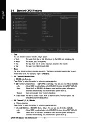
... BIOS to select this to 31 (or the maximum allowed in the month) Year The year, from 1999 through 2098 Time The times format in . GA-M61PM-S2 (rev. 2.0) Motherboard - 32 - The time is , , , . English 2-1 Standard CMOS Features CMOS Setup Utility-Copyright (C) 1984-2006 Award Software Standard CMOS Features Date (mm:dd:yy) Time...
... BIOS to select this to 31 (or the maximum allowed in the month) Year The year, from 1999 through 2098 Time The times format in . GA-M61PM-S2 (rev. 2.0) Motherboard - 32 - The time is , , , . English 2-1 Standard CMOS Features CMOS Setup Utility-Copyright (C) 1984-2006 Award Software Standard CMOS Features Date (mm:dd:yy) Time...
Manual
Page 34
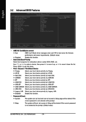
... system can not boot and can not access to Setup will be denied if the correct password is not entered at the prompt. (Default value) GA-M61PM-S2 (rev. 2.0) Motherboard - 34 - LS120 Hard Disk Select your boot device priority by LS120. USB-HDD Select your boot device priority by USB-HDD. Setup The system...
... system can not boot and can not access to Setup will be denied if the correct password is not entered at the prompt. (Default value) GA-M61PM-S2 (rev. 2.0) Motherboard - 34 - LS120 Hard Disk Select your boot device priority by LS120. USB-HDD Select your boot device priority by USB-HDD. Setup The system...

Manual
Page 36
Disabled (Default value) Disable this function. GA-M61PM-S2 (rev. 2.0) Motherboard - 36 - NV SATA 1 Secondary RAID Enabled Enable RAID function for the first channel of the first SATA 3Gb/s controller. Disable the RAID function for ...
Disabled (Default value) Disable this function. GA-M61PM-S2 (rev. 2.0) Motherboard - 36 - NV SATA 1 Secondary RAID Enabled Enable RAID function for the first channel of the first SATA 3Gb/s controller. Disable the RAID function for ...

Manual
Page 38
... about 1.6m on a specified pair of wires will be the approximate distance to the following message will operate at a speed of the attached LAN cable GA-M61PM-S2 (rev. 2.0) Motherboard - 38 - This feature will only operate at a normal speed of 10/100/1000Mbps in Windows mode or when the LAN Boot ROM is the...
... about 1.6m on a specified pair of wires will be the approximate distance to the following message will operate at a speed of the attached LAN cable GA-M61PM-S2 (rev. 2.0) Motherboard - 38 - This feature will only operate at a normal speed of 10/100/1000Mbps in Windows mode or when the LAN Boot ROM is the...
Manual
Page 40
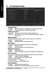
...-Off by Power button Instant-Off Press power button then Power off . to Power off instantly. (Default value) Delay 4 Sec. Disabled Enabled Disable this function. GA-M61PM-S2 (rev. 2.0) Motherboard - 40 - Enable PME as wake up system from suspend mode. (Default value) Power-On by Alarm You can awake the system from any suspend...
...-Off by Power button Instant-Off Press power button then Power off . to Power off instantly. (Default value) Delay 4 Sec. Disabled Enabled Disable this function. GA-M61PM-S2 (rev. 2.0) Motherboard - 40 - Enable PME as wake up system from suspend mode. (Default value) Power-On by Alarm You can awake the system from any suspend...


