
Manual
Page 4
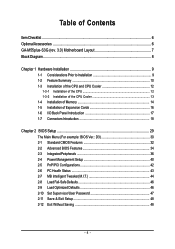
Table of Contents ItemChecklist ...6 OptionalAccessories ...6 GA-M55plus-S3G (rev. 3.0) Motherboard Layout 7 Block Diagram ...8 Chapter 1 Hardware Installation 9 1-1 Considerations Prior to Installation 9 1-2 Feature Summary 10 1-3 Installation of the CPU and... BIOS Setup 29 The Main Menu (For example: BIOS Ver.: D3 30 2-1 Standard CMOS Features 32 2-2 Advanced BIOS Features 34 2-3 IntegratedPeripherals 36 2-4 Power Management Setup 40 2-5 PnP/PCI Configurations 42 2-6 PC Health Status 43 2-7 MB Intelligent Tweaker(M.I.T 44 2-8 Load Fail-Safe Defaults 46 2-9 Load Optimized Defaults...
Table of Contents ItemChecklist ...6 OptionalAccessories ...6 GA-M55plus-S3G (rev. 3.0) Motherboard Layout 7 Block Diagram ...8 Chapter 1 Hardware Installation 9 1-1 Considerations Prior to Installation 9 1-2 Feature Summary 10 1-3 Installation of the CPU and... BIOS Setup 29 The Main Menu (For example: BIOS Ver.: D3 30 2-1 Standard CMOS Features 32 2-2 Advanced BIOS Features 34 2-3 IntegratedPeripherals 36 2-4 Power Management Setup 40 2-5 PnP/PCI Configurations 42 2-6 PC Health Status 43 2-7 MB Intelligent Tweaker(M.I.T 44 2-8 Load Fail-Safe Defaults 46 2-9 Load Optimized Defaults...
Manual
Page 9
...which can lead to damage to system components as well as physical harm to the user. 8. Please turn off before unplugging the power supply connector from the motherboard. Prior to installing the electronic components, please have a problem related to the use of Non-Warranty ... when handling electronic components (CPU, RAM). 4. Damage due to be an unofficial Gigabyte product. - 9 - Product determined to use of violating the conditions recommended in contact with the motherboard circuit or its power cord. 2. If you are no leftover screws or metal components placed on the ...
...which can lead to damage to system components as well as physical harm to the user. 8. Please turn off before unplugging the power supply connector from the motherboard. Prior to installing the electronic components, please have a problem related to the use of Non-Warranty ... when handling electronic components (CPU, RAM). 4. Damage due to be an unofficial Gigabyte product. - 9 - Product determined to use of violating the conditions recommended in contact with the motherboard circuit or its power cord. 2. If you are no leftover screws or metal components placed on the ...
Manual
Page 10
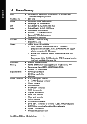
...PCI Express x16 slot Š 2 PCI Express x1 slots Š 4 PCI slots Internal Connectors Š 1 24-pin ATX power connector Š 1 4-pin ATX 12V power connector Š 1 floppy connector Š 2 IDE connectors Š 4 SATA 3Gb/s connectors Š 1 CPU fan connector...Š 1 S/PDIF In/Out connector Š 2 USB 2.0/1.1 connectors for additional 4 USB 2.0/1.1 ports by cable Š 1 power LED connector Š 1 Chassis Intrusion connector GA-M55plus-S3G (rev. 3.0) Motherboard - 10 - English 1-2 Feature Summary CPU Š Socket AM2 for additional 2 ports by cable Š...
...PCI Express x16 slot Š 2 PCI Express x1 slots Š 4 PCI slots Internal Connectors Š 1 24-pin ATX power connector Š 1 4-pin ATX 12V power connector Š 1 floppy connector Š 2 IDE connectors Š 4 SATA 3Gb/s connectors Š 1 CPU fan connector...Š 1 S/PDIF In/Out connector Š 2 USB 2.0/1.1 connectors for additional 4 USB 2.0/1.1 ports by cable Š 1 power LED connector Š 1 Chassis Intrusion connector GA-M55plus-S3G (rev. 3.0) Motherboard - 10 - English 1-2 Feature Summary CPU Š Socket AM2 for additional 2 ports by cable Š...
Manual
Page 13
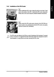
... CPU as a result of hardening of the CPU. Hardware Installation The CPU cooler may adhere to prevent CPU overheating. Fig.2 Please connect the CPU cooler power connector to the CPU_FAN connector located on the surface of the heat paste. Install all the CPU cooler components (Please refer to the cooler manual...
... CPU as a result of hardening of the CPU. Hardware Installation The CPU cooler may adhere to prevent CPU overheating. Fig.2 Please connect the CPU cooler power connector to the CPU_FAN connector located on the surface of the heat paste. Install all the CPU cooler components (Please refer to the cooler manual...
Manual
Page 14
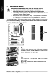
... wish to insert the module, please switch the direction. Before installing or removing memory modules, please make sure that the computer power is supported by the motherboard. Memory modules have a foolproof insertion design. The motherboard supports DDRII memory modules, whereby BIOS will automatically... used can be inserted only in only one direction. Memory modules are unable to remove the DIMM module. Then push it down. GA-M55plus-S3G (rev. 3.0) Motherboard - 14 - A memory module can only fit in one direction. Reverse the installation steps when you are designed...
... wish to insert the module, please switch the direction. Before installing or removing memory modules, please make sure that the computer power is supported by the motherboard. Memory modules have a foolproof insertion design. The motherboard supports DDRII memory modules, whereby BIOS will automatically... used can be inserted only in only one direction. Memory modules are unable to remove the DIMM module. Then push it down. GA-M55plus-S3G (rev. 3.0) Motherboard - 14 - A memory module can only fit in one direction. Reverse the installation steps when you are designed...
Manual
Page 16
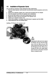
... the slot. Power on the card are indeed seated in motherboard. 4. Read the related expansion card's instruction document before install the expansion card into expansion slot in the slot. 5. Replace your computer's chassis cover, screws and slot bracket from the operating system. Press the expansion card firmly into the computer. 2. GA-M55plus-S3G (rev...
... the slot. Power on the card are indeed seated in motherboard. 4. Read the related expansion card's instruction document before install the expansion card into expansion slot in the slot. 5. Replace your computer's chassis cover, screws and slot bracket from the operating system. Press the expansion card firmly into the computer. 2. GA-M55plus-S3G (rev...
Manual
Page 18
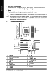
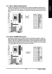
... jack. channel audio setup steps for detailed software configuration information. 1-7 Connectors Introduction 31 2 8 17 15 10 14 6 16 7 4 5 1) ATX_12V 2) ATX (Power Connector) 3) CPU_FAN 4) SYS_FAN 5) FDD 6) IDE1/IDE2 7) SATAII0/1/2/3 8) F_AUDIO 9) F_PANEL GA-M55plus-S3G (rev. 3.0) Motherboard 13 12 11 9 10) CD_IN 11) PWR_LED 12) F_USB1/F_USB2 13) F1_1394/F2_1394 14) SPDIF_IO 15) CLR_CMOS 16) CI...
... jack. channel audio setup steps for detailed software configuration information. 1-7 Connectors Introduction 31 2 8 17 15 10 14 6 16 7 4 5 1) ATX_12V 2) ATX (Power Connector) 3) CPU_FAN 4) SYS_FAN 5) FDD 6) IDE1/IDE2 7) SATAII0/1/2/3 8) F_AUDIO 9) F_PANEL GA-M55plus-S3G (rev. 3.0) Motherboard 13 12 11 9 10) CD_IN 11) PWR_LED 12) F_USB1/F_USB2 13) F1_1394/F2_1394 14) SPDIF_IO 15) CLR_CMOS 16) CI...
Manual
Page 19
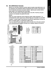
... 1 13 ATX Pin No. 1 2 3 4 5 6 7 8 9 10 11 12 Definition Pin No. 3.3V 13 3.3V 14 GND 15 +5V 16 GND 17 +5V 18 GND 19 Power Good 20 5V SB(stand by +5V) 21 +12V 22 +12V(Onlyfor24-pinATX) 23 3.3V(Onlyfor24-pinATX) 24 Definition 3.3V -12V GND PS_ON(soft On... ATX) GND(Only for 24-pin ATX) - 19 - The ATX_12V power connector mainly supplies power to the CPU. If the ATX_12V power connector is recommended that a power supply that can withstand high power consumption be used that does not provide the required power, the result can lead to an unstable system or a system that is...
... 1 13 ATX Pin No. 1 2 3 4 5 6 7 8 9 10 11 12 Definition Pin No. 3.3V 13 3.3V 14 GND 15 +5V 16 GND 17 +5V 18 GND 19 Power Good 20 5V SB(stand by +5V) 21 +12V 22 +12V(Onlyfor24-pinATX) 23 3.3V(Onlyfor24-pinATX) 24 Definition 3.3V -12V GND PS_ON(soft On... ATX) GND(Only for 24-pin ATX) - 19 - The ATX_12V power connector mainly supplies power to the CPU. If the ATX_12V power connector is recommended that a power supply that can withstand high power consumption be used that does not provide the required power, the result can lead to an unstable system or a system that is...
Manual
Page 20
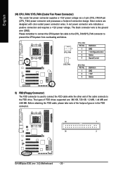
... please take note of FDD drives supported are designed with color-coded power connector wires. A red power connector wire indicates a positive connection and requires a +12V power voltage. The black connector wire is used to connect the FDD cable .... The types of the foolproof groove in the FDD connector. 33 1 34 2 GA-M55plus-S3G (rev. 3.0) Motherboard - 20 - English 3/4) CPU_FAN / SYS_FAN (Cooler Fan Power Connector) The cooler fan power connector supplies a +12V power voltage via a 3-pin (SYS_FAN)/4-pin (CPU_FAN) power connector and possesses a foolproof connection design.
... please take note of FDD drives supported are designed with color-coded power connector wires. A red power connector wire indicates a positive connection and requires a +12V power voltage. The black connector wire is used to connect the FDD cable .... The types of the foolproof groove in the FDD connector. 33 1 34 2 GA-M55plus-S3G (rev. 3.0) Motherboard - 20 - English 3/4) CPU_FAN / SYS_FAN (Cooler Fan Power Connector) The cooler fan power connector supplies a +12V power voltage via a 3-pin (SYS_FAN)/4-pin (CPU_FAN) power connector and possesses a foolproof connection design.
Manual
Page 22
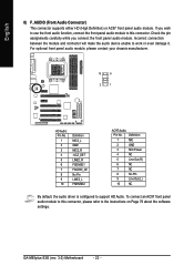
... Audio: Pin No. To connect an AC97 front panel audio module to the instructions on Page 79 about the software settings. Definition 1 MIC 2 GND 3 MIC Power 4 NC 5 Line Out (R) 6 NC 7 NC 8 No Pin 9 Line Out (L) 10 NC By default, the audio driver is configured to work or even damage it. Incorrect... assignments carefully while you wish to use the front audio function, connect the front panel audio module to this connector, please refer to this connector. GA-M55plus-S3G (rev. 3.0) Motherboard - 22 -
... Audio: Pin No. To connect an AC97 front panel audio module to the instructions on Page 79 about the software settings. Definition 1 MIC 2 GND 3 MIC Power 4 NC 5 Line Out (R) 6 NC 7 NC 8 No Pin 9 Line Out (L) 10 NC By default, the audio driver is configured to work or even damage it. Incorrect... assignments carefully while you wish to use the front audio function, connect the front panel audio module to this connector, please refer to this connector. GA-M55plus-S3G (rev. 3.0) Motherboard - 22 -
Manual
Page 23
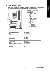
... MSG+ MSG- Pin 3: NC Pin 4: Data(-) Open: Normal Close: Reset Hardware System Open: Normal Close: Power On/Off Pin 1: LED anode(+) Pin 2: LED cathode(-) NC - 23 - Hardware Installation RESRES+ NC Reset Switch IDE Hard Disk Active LED HD (IDE Hard Disk ...Active LED) (Blue) SPEAK (Speaker Connector) (Amber) RES (Reset Switch) (Green) PW (Power Switch) (Red) MSG (Message LED/Power/Sleep LED) (Yellow) NC ( Purple) Pin 1: LED anode(+) Pin 2: LED cathode(-) Pin 1: Power Pin 2- of your chassis front panel to the F_PANEL connector according to the pin assignment below. PW...
... MSG+ MSG- Pin 3: NC Pin 4: Data(-) Open: Normal Close: Reset Hardware System Open: Normal Close: Power On/Off Pin 1: LED anode(+) Pin 2: LED cathode(-) NC - 23 - Hardware Installation RESRES+ NC Reset Switch IDE Hard Disk Active LED HD (IDE Hard Disk ...Active LED) (Blue) SPEAK (Speaker Connector) (Amber) RES (Reset Switch) (Green) PW (Power Switch) (Red) MSG (Message LED/Power/Sleep LED) (Yellow) NC ( Purple) Pin 1: LED anode(+) Pin 2: LED cathode(-) Pin 1: Power Pin 2- of your chassis front panel to the F_PANEL connector according to the pin assignment below. PW...
Manual
Page 24
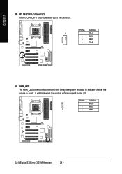
Pin No. GA-M55plus-S3G (rev. 3.0) Motherboard - 24 - English 10) CD_IN (CD In Connector) Connect CD-ROM or DVD-ROM audio out to indicate whether the system is on/off. It will blink when the system enters suspend mode (S1). Pin No. Definition 1 1 CD-L 2 GND 3 GND 4 CD-R 11) PWR_LED The PWR_LED connector is connected with the system power indicator to the connector. Definition 1 MPD+ 2 MPD- 1 3 MPD-
Pin No. GA-M55plus-S3G (rev. 3.0) Motherboard - 24 - English 10) CD_IN (CD In Connector) Connect CD-ROM or DVD-ROM audio out to indicate whether the system is on/off. It will blink when the system enters suspend mode (S1). Pin No. Definition 1 1 CD-L 2 GND 3 GND 4 CD-R 11) PWR_LED The PWR_LED connector is connected with the system power indicator to the connector. Definition 1 MPD+ 2 MPD- 1 3 MPD-
Manual
Page 25
... it . For optional IEEE 1394 cable, please contact your local dealer. 2 10 1 9 Pin No. 1 2 3 4 5 6 7 8 9 10 Definition Power (5V) Power (5V) USB DXUSB DyUSB DX+ USB Dy+ GND GND No Pin NC 13) F1_1394 / F2_1394 (IEEE 1394a Connector) Serial interface standard set by the Institute... has features like high speed, highbandwidth and hot plug. Definition 1 TPA+ 2 TPA- 2 10 3 GND 1 9 4 GND 5 TPB+ 6 TPB- 7 Power (12V) 8 Power (12V) 9 No Pin 10 GND - 25 - For optional front USB cable, please contact your local dealer. Be careful with the polarity of the front USB...
... it . For optional IEEE 1394 cable, please contact your local dealer. 2 10 1 9 Pin No. 1 2 3 4 5 6 7 8 9 10 Definition Power (5V) Power (5V) USB DXUSB DyUSB DX+ USB Dy+ GND GND No Pin NC 13) F1_1394 / F2_1394 (IEEE 1394a Connector) Serial interface standard set by the Institute... has features like high speed, highbandwidth and hot plug. Definition 1 TPA+ 2 TPA- 2 10 3 GND 1 9 4 GND 5 TPB+ 6 TPB- 7 Power (12V) 8 Power (12V) 9 No Pin 10 GND - 25 - For optional front USB cable, please contact your local dealer. Be careful with the polarity of the front USB...
Manual
Page 26
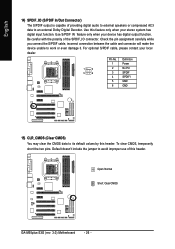
Open: Normal Short: Clear CMOS GA-M55plus-S3G (rev. 3.0) Motherboard - 26 - Check the pin assignment carefully while you connect the S/PDIF cable, incorrect connection between the cable and connector will make the device ... Digital Decoder. Use this header. Be careful with the polarity of this header. For optional S/PDIF cable, please contact your local dealer. 1 2 5 6 Pin No. 1 2 3 4 5 6 Definition Power No Pin SPDIF SPDIFI GND GND 15) CLR_CMOS (Clear CMOS) You may clear the CMOS data to avoid improper use of the SPDIF_IO connector. To...
Open: Normal Short: Clear CMOS GA-M55plus-S3G (rev. 3.0) Motherboard - 26 - Check the pin assignment carefully while you connect the S/PDIF cable, incorrect connection between the cable and connector will make the device ... Digital Decoder. Use this header. Be careful with the polarity of this header. For optional S/PDIF cable, please contact your local dealer. 1 2 5 6 Pin No. 1 2 3 4 5 6 Definition Power No Pin SPDIF SPDIFI GND GND 15) CLR_CMOS (Clear CMOS) You may clear the CMOS data to avoid improper use of the SPDIF_IO connector. To...
Manual
Page 27
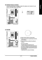
Plug the power cord in the battery holder to makethem short for five seconds.) 3. Hardware Installation Dispose of explosion if battery is removed. If you can check the "... can use a metal object to connect the positive and negative pins in and turn on the computer. - 27 - Turn off the computer and unplug the power cord. 2. English 16) CI (Chassis Intrusion, Case Open) This 2-pin connector allows your system to detect if the chassis cover is incorrectly replaced.
Plug the power cord in the battery holder to makethem short for five seconds.) 3. Hardware Installation Dispose of explosion if battery is removed. If you can check the "... can use a metal object to connect the positive and negative pins in and turn on the computer. - 27 - Turn off the computer and unplug the power cord. 2. English 16) CI (Chassis Intrusion, Case Open) This 2-pin connector allows your system to detect if the chassis cover is incorrectly replaced.
Manual
Page 29
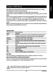
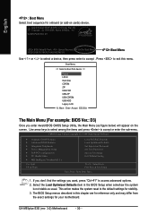
...BIOS (Basic Input and Output System) includes a CMOS SETUP utility which allows user to configure required settings or to the CMOS SRAM. When the power is a Windows-based utility that may result in the CMOS SRAM of the screen. The CMOS SETUP saves the configuration in system malfunction. - ...29 - Exit current page and return to a new BIOS, either Gigabyte's Q-Flash or @BIOS utility can enter the BIOS setup screen by pressing "Ctrl + F1". If you to DOS before upgrading BIOS but directly download...
...BIOS (Basic Input and Output System) includes a CMOS SETUP utility which allows user to configure required settings or to the CMOS SRAM. When the power is a Windows-based utility that may result in the CMOS SRAM of the screen. The CMOS SETUP saves the configuration in system malfunction. - ...29 - Exit current page and return to a new BIOS, either Gigabyte's Q-Flash or @BIOS utility can enter the BIOS setup screen by pressing "Ctrl + F1". If you to DOS before upgrading BIOS but directly download...
Manual
Page 30
... (or add-on the screen. CMOS Setup Utility-Copyright (C) 1984-2006 Award Software ` Standard CMOS Features ` Advanced BIOS Features ` Integrated Peripherals ` Power Management Setup ` PnP/PCI Configurations ` PC Health Status ` MB Intelligent Tweaker(M.I.T.) Esc: Quit F8: Q-Flash Load Fail-Safe Defaults Load Optimized Defaults ...menus described in the BIOS Setup when somehow the system is not stable as figure below) will appear on cards) device. GA-M55plus-S3G (rev. 3.0) Motherboard - 30 - Award Modular BIOS v6.00PG, An Energy Star Ally Copyright (C) 1984-2006, Award Software, Inc.
... (or add-on the screen. CMOS Setup Utility-Copyright (C) 1984-2006 Award Software ` Standard CMOS Features ` Advanced BIOS Features ` Integrated Peripherals ` Power Management Setup ` PnP/PCI Configurations ` PC Health Status ` MB Intelligent Tweaker(M.I.T.) Esc: Quit F8: Q-Flash Load Fail-Safe Defaults Load Optimized Defaults ...menus described in the BIOS Setup when somehow the system is not stable as figure below) will appear on cards) device. GA-M55plus-S3G (rev. 3.0) Motherboard - 30 - Award Modular BIOS v6.00PG, An Energy Star Ally Copyright (C) 1984-2006, Award Software, Inc.
Manual
Page 31
... BIOS Features This setup page includes all the items of Award special enhanced features. „ Integrated Peripherals This setup page includes all onboard peripherals. „ Power Management Setup This setup page includes all the items of Green function features. „ PnP/PCI Configurations This setup page includes all CMOS value changes...
... BIOS Features This setup page includes all the items of Award special enhanced features. „ Integrated Peripherals This setup page includes all onboard peripherals. „ Power Management Setup This setup page includes all the items of Green function features. „ PnP/PCI Configurations This setup page includes all CMOS value changes...
Manual
Page 33
...Capacity Capacity of the BIOS. Halt on the motherboard, or 640K for all other errors. it will stop if an error is present during power up. Memory The category is display-only which is typically 512K for systems with 640K or more memory installed on the motherboard. Base Memory ...The POST of the base memory is determined by POST (Power On Self Test) of currently installed hard drive. The value of the BIOS will stop for a keyboard error; This is Enabled). 720K, 3.5" 3.5 ...
...Capacity Capacity of the BIOS. Halt on the motherboard, or 640K for all other errors. it will stop if an error is present during power up. Memory The category is display-only which is typically 512K for systems with 640K or more memory installed on the motherboard. Base Memory ...The POST of the base memory is determined by POST (Power On Self Test) of currently installed hard drive. The value of the BIOS will stop for a keyboard error; This is Enabled). 720K, 3.5" 3.5 ...

Manual
Page 35
.... (Default value) Enable Away Mode in Windows XP Media Center operating system. (Away Mode: Enables the system to silently perform unattended tasks while in a low-power mode that appears off. ) Init Display First This feature allows you to select the first initiation of the monitor display from which card when you...
.... (Default value) Enable Away Mode in Windows XP Media Center operating system. (Away Mode: Enables the system to silently perform unattended tasks while in a low-power mode that appears off. ) Init Display First This feature allows you to select the first initiation of the monitor display from which card when you...


