
Manual
Page 3
...gigabyte.com.tw Identifying Your Motherboard Revision The revision number on our website. sive global distributor of the motherboard is designated by GIGA-BYTE TECHNOLOGY CO., LTD. Example: GIGABYTE... UNITED INC. Documentation Classifications In order to assist in the use of this product, GIGABYTE provides...GIGABYTE without GIGABYTE's prior written permission. Copyright © 2007 GIGA-BYTE TECHNOLOGY CO., LTD. All rights reserved. No part of GIGABYTE..."REV: X.X." Changes to use GIGABYTE's unique features, read or download the information on/...
...gigabyte.com.tw Identifying Your Motherboard Revision The revision number on our website. sive global distributor of the motherboard is designated by GIGA-BYTE TECHNOLOGY CO., LTD. Example: GIGABYTE... UNITED INC. Documentation Classifications In order to assist in the use of this product, GIGABYTE provides...GIGABYTE without GIGABYTE's prior written permission. Copyright © 2007 GIGA-BYTE TECHNOLOGY CO., LTD. All rights reserved. No part of GIGABYTE..."REV: X.X." Changes to use GIGABYTE's unique features, read or download the information on/...
Manual
Page 4
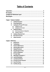
Table of Contents OptionalItems ...6 Box Contents ...6 GA-M52S-S3P Motherboard Layout 7 Block Diagram ...8 Chapter 1 Hardware Installation 9 1-1 Installation Precautions 9 1-2 Product Specifications 10 1-3 Installing the CPU and CPU Cooler 12... Memory 16 1-5 Installing an Expansion Card 17 1-6 Back Panel Connectors 18 1-7 Internal Connectors 20 Chapter 2 BIOS Setup 31 2-1 Startup Screen 32 2-2 The Main Menu 33 2-3 Standard CMOS Features 35 2-4 Advanced BIOS Features 37 2-5 IntegratedPeripherals 39 2-6 Power Management Setup 43 2-7 PnP/PCI Configurations 45 2-8 PC Health Status ...
Table of Contents OptionalItems ...6 Box Contents ...6 GA-M52S-S3P Motherboard Layout 7 Block Diagram ...8 Chapter 1 Hardware Installation 9 1-1 Installation Precautions 9 1-2 Product Specifications 10 1-3 Installing the CPU and CPU Cooler 12... Memory 16 1-5 Installing an Expansion Card 17 1-6 Back Panel Connectors 18 1-7 Internal Connectors 20 Chapter 2 BIOS Setup 31 2-1 Startup Screen 32 2-2 The Main Menu 33 2-3 Standard CMOS Features 35 2-4 Advanced BIOS Features 37 2-5 IntegratedPeripherals 39 2-6 Power Management Setup 43 2-7 PnP/PCI Configurations 45 2-8 PC Health Status ...

Manual
Page 5
... 54 3-3 Driver CD Information 54 3-4 Hardware Information 55 3-5 Contact Us ...55 Chapter 4 Unique Features 57 4-1 Xpress Recovery2 57 4-2 BIOS Update Utilities 62 4-2-1 Updating the BIOS with the Q-Flash Utility 62 4-2-2 Updating the BIOS with the @BIOS Utility 65 4-3 EasyTune 5 ...67 4-4 Windows Vista ReadyBoost 68 Chapter 5 Appendix ...69 5-1 Configuring SATA Hard Drive(s 69 5-1-1 Configuring the...
... 54 3-3 Driver CD Information 54 3-4 Hardware Information 55 3-5 Contact Us ...55 Chapter 4 Unique Features 57 4-1 Xpress Recovery2 57 4-2 BIOS Update Utilities 62 4-2-1 Updating the BIOS with the Q-Flash Utility 62 4-2-2 Updating the BIOS with the @BIOS Utility 65 4-3 EasyTune 5 ...67 4-4 Windows Vista ReadyBoost 68 Chapter 5 Appendix ...69 5-1 Configuring SATA Hard Drive(s 69 5-1-1 Configuring the...
Manual
Page 7
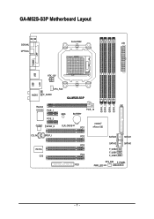
GA-M52S-S3P Motherboard Layout KB_MS COAXIAL Socket AM2 ATX OPTICAL COMA LPT USB USB LAN ATX_12V AUDIO CPU_FAN F_AUDIO GA-M52S-S3P DDRII_1 DDRII_2 DDRII_3 DDRII_4 Realtek 8110SC PCIE_1 IDE PCIE_16 BIOS BATTERY PCIE_2 nVIDIA® CODEC SPDIF_O CLR_CMOS PCI1 nForce 520 CD_IN SPDIF_I IT8716 CI PCI2 PCI3 PCI4 FDD SATAII3 SATAII1 SATAII2 SATAII0 F_USB2 F_USB1 F_USB3 SYS_FAN F_PANEL PWR_LED - 7 -
GA-M52S-S3P Motherboard Layout KB_MS COAXIAL Socket AM2 ATX OPTICAL COMA LPT USB USB LAN ATX_12V AUDIO CPU_FAN F_AUDIO GA-M52S-S3P DDRII_1 DDRII_2 DDRII_3 DDRII_4 Realtek 8110SC PCIE_1 IDE PCIE_16 BIOS BATTERY PCIE_2 nVIDIA® CODEC SPDIF_O CLR_CMOS PCI1 nForce 520 CD_IN SPDIF_I IT8716 CI PCI2 PCI3 PCI4 FDD SATAII3 SATAII1 SATAII2 SATAII0 F_USB2 F_USB1 F_USB3 SYS_FAN F_PANEL PWR_LED - 7 -

Manual
Page 8
Block Diagram PCIe CLK (100 MHz) AMD Socket AM2 CPU CPU CLK+/-(200 MHz) DDR2 800/667/533 MHz DIMM Dual Channel Memory Hyper Transport Bus PCI Express x16 PCI Express x1 Bus x1 x1 PCIe CLK (100 MHz) 2 PCI Express x1 PCI Bus RTL 8110SC RJ45 LAN 4 PCI nVIDIA® nForce 520 4 SATA 3Gb/s ATA-133/100/66/33 IDE Channel CODEC LPC BUS IT8716 BIOS Floppy LPT Port COM Port PS/2 KB/Mouse 10 USB Ports Surround Speaker Out Center/Subwoofer Spear Out Side Speaker Out MIC Line-Out Line-In SPDIF In SPDIF Out PCI CLK (33 MHz) - 8 -
Block Diagram PCIe CLK (100 MHz) AMD Socket AM2 CPU CPU CLK+/-(200 MHz) DDR2 800/667/533 MHz DIMM Dual Channel Memory Hyper Transport Bus PCI Express x16 PCI Express x1 Bus x1 x1 PCIe CLK (100 MHz) 2 PCI Express x1 PCI Bus RTL 8110SC RJ45 LAN 4 PCI nVIDIA® nForce 520 4 SATA 3Gb/s ATA-133/100/66/33 IDE Channel CODEC LPC BUS IT8716 BIOS Floppy LPT Port COM Port PS/2 KB/Mouse 10 USB Ports Surround Speaker Out Center/Subwoofer Spear Out Side Speaker Out MIC Line-Out Line-In SPDIF In SPDIF Out PCI CLK (33 MHz) - 8 -

Manual
Page 11
...warning Š CPU/System fan speed control (Note 2) Š 1 x 4 Mbit flash Š Use of licensed AWARD BIOS Š PnP 1.0a, DMI 2.0, SM BIOS 2.3, ACPI 1.0b Š Support for @BIOS Š Support for Download Center Š Support for Q-Flash Š Support for EasyTune (Note 3) Š Support for ...Xpress Install Š Support for Xpress Recovery2 Š Support for Virtual Dual BIOS Š Norton Internet Security (OEM version) Š Support for Microsoft® Windows® Vista/XP/2000 Š ATX form factor; 30.5cm ...
...warning Š CPU/System fan speed control (Note 2) Š 1 x 4 Mbit flash Š Use of licensed AWARD BIOS Š PnP 1.0a, DMI 2.0, SM BIOS 2.3, ACPI 1.0b Š Support for @BIOS Š Support for Download Center Š Support for Q-Flash Š Support for EasyTune (Note 3) Š Support for ...Xpress Install Š Support for Xpress Recovery2 Š Support for Virtual Dual BIOS Š Norton Internet Security (OEM version) Š Support for Microsoft® Windows® Vista/XP/2000 Š ATX form factor; 30.5cm ...

Manual
Page 15
...; Make sure that memory of the same capacity, brand, speed, and chips be used and installed in only one DDR2 memory module is installed, the BIOS will double the original memory bandwidth. A memory module can be enabled if only one direction. If you install them in Dual Channel mode. 1. English 1-4 Installing... is recommended that the motherboard supports the memory. It is recommended that memory of the same capacity, brand, speed, and chips be used . (Go to GIGABYTE's website for optimum performance. - 15 -
...; Make sure that memory of the same capacity, brand, speed, and chips be used and installed in only one DDR2 memory module is installed, the BIOS will double the original memory bandwidth. A memory module can be enabled if only one direction. If you install them in Dual Channel mode. 1. English 1-4 Installing... is recommended that the motherboard supports the memory. It is recommended that memory of the same capacity, brand, speed, and chips be used . (Go to GIGABYTE's website for optimum performance. - 15 -

Manual
Page 17
... install an expansion card: • Make sure the motherboard supports the expansion card. Align the card with a screw. 5. If necessary, go to BIOS Setup to make any required BIOS changes for your expansion card in the expansion slot. 1. PCI Express x16 Slot PCI Express x1 Slot PCI Slot Follow the steps below...
... install an expansion card: • Make sure the motherboard supports the expansion card. Align the card with a screw. 5. If necessary, go to BIOS Setup to make any required BIOS changes for your expansion card in the expansion slot. 1. PCI Express x16 Slot PCI Express x1 Slot PCI Slot Follow the steps below...
Manual
Page 24
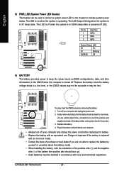
... S3/S4/S5 Off 9) BATTERY The battery provides power to keep the values (such as BIOS configurations, date, and time information) in the CMOS when the computer is operating. Plug in accordance with local environmental regulations. GA-M52S-S3P Motherboard - 24 - The LED is on the chassis to indicate system power status. The LED...
... S3/S4/S5 Off 9) BATTERY The battery provides power to keep the values (such as BIOS configurations, date, and time information) in the CMOS when the computer is operating. Plug in accordance with local environmental regulations. GA-M52S-S3P Motherboard - 24 - The LED is on the chassis to indicate system power status. The LED...

Manual
Page 25
...the pin assignments below. Note the positive and negative pins before connecting the cables. When connecting your system using the power switch (refer to Chapter 2, "BIOS Setup," "Power Management Setup," for information about beep codes. • HD (IDE Hard Drive Activity LED, Blue) Connects to the hard drive activity ..., make sure the wire assignments and the pin assignments are matched correctly. - 25 - The LED is off when the system is detected, the BIOS may differ by issuing a beep code. If a problem is in S3/S4/S5 Off S3/S4 sleep state or powered off your chassis front ...
...the pin assignments below. Note the positive and negative pins before connecting the cables. When connecting your system using the power switch (refer to Chapter 2, "BIOS Setup," "Power Management Setup," for information about beep codes. • HD (IDE Hard Drive Activity LED, Blue) Connects to the hard drive activity ..., make sure the wire assignments and the pin assignments are matched correctly. - 25 - The LED is off when the system is detected, the BIOS may differ by issuing a beep code. If a problem is in S3/S4/S5 Off S3/S4 sleep state or powered off your chassis front ...

Manual
Page 29
...Failure to do so may cause damage to the motherboard. • After system restart, go to BIOS Setup to load factory defaults (select Load Optimized Defaults) or manually configure the BIOS settings (refer to Chapter 2, "BIOS Setup," for a few seconds. Open: Normal Short: Clear CMOS Values • Always turn off ... to clear the CMOS values (e.g. Hardware Installation English 17) CLR_CMOS (Clearing CMOS Jumper) Use this jumper to touch the two pins for BIOS configurations). - 29 - To clear the CMOS values, place a jumper cap on your computer, be sure to factory defaults.
...Failure to do so may cause damage to the motherboard. • After system restart, go to BIOS Setup to load factory defaults (select Load Optimized Defaults) or manually configure the BIOS settings (refer to Chapter 2, "BIOS Setup," for a few seconds. Open: Normal Short: Clear CMOS Values • Always turn off ... to clear the CMOS values (e.g. Hardware Installation English 17) CLR_CMOS (Clearing CMOS Jumper) Use this jumper to touch the two pins for BIOS configurations). - 29 - To clear the CMOS values, place a jumper cap on your computer, be sure to factory defaults.

Manual
Page 31
... this chapter or introductions of the system in the CMOS on using the current version of BIOS from the Internet and updates the BIOS. To upgrade the BIOS, use either the GIGABYTE Q-Flash or @BIOS utility. • Q-Flash allows the user to keep the configuration values in the main ...menu of the BIOS Setup program. For instructions on the motherboard. To access the BIOS Setup program, press the key...
... this chapter or introductions of the system in the CMOS on using the current version of BIOS from the Internet and updates the BIOS. To upgrade the BIOS, use either the GIGABYTE Q-Flash or @BIOS utility. • Q-Flash allows the user to keep the configuration values in the main ...menu of the BIOS Setup program. For instructions on the motherboard. To access the BIOS Setup program, press the key...
Manual
Page 32
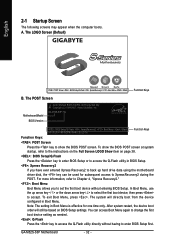
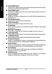
... Menu again to change the first boot device setting as needed. : Q-Flash Press the key to access the Q-Flash utility directly without entering BIOS Setup. GA-M52S-S3P Motherboard - 32 - GA-M52S-S3P FAc . . . . : BIOS Setup/Q-Flash : XpressRecovery2 : Boot Menu : Qflash 06/15/2007-NF-MCP65-6A61LG02C-00 Function Keys Function Keys: : POST Screen Press the key to...
... Menu again to change the first boot device setting as needed. : Q-Flash Press the key to access the Q-Flash utility directly without entering BIOS Setup. GA-M52S-S3P Motherboard - 32 - GA-M52S-S3P FAc . . . . : BIOS Setup/Q-Flash : XpressRecovery2 : Boot Menu : Qflash 06/15/2007-NF-MCP65-6A61LG02C-00 Function Keys Function Keys: : POST Screen Press the key to...

Manual
Page 33
... (General Help) of function keys available for the current submenus Access the Q-Flash utility Display system information Save all the changes and exit the BIOS Setup program Main Menu Help The onscreen description of a highlighted setup option is not stable as shown below) appears on the screen. Use arrow...F8: Q-Flash KLJI: Select Item F10: Save & Exit Setup Time, Date, Hard Disk Type... Submenu Help While in a submenu, press to display a help screen. BIOS Setup Help for each item is in the Item Help block on the right side of the submenu. • If you do not find the...
... (General Help) of function keys available for the current submenus Access the Q-Flash utility Display system information Save all the changes and exit the BIOS Setup program Main Menu Help The onscreen description of a highlighted setup option is not stable as shown below) appears on the screen. Use arrow...F8: Q-Flash KLJI: Select Item F10: Save & Exit Setup Time, Date, Hard Disk Type... Submenu Help While in a submenu, press to display a help screen. BIOS Setup Help for each item is in the Item Help block on the right side of the submenu. • If you do not find the...
Manual
Page 34
... Setup Save all the changes made in the BIOS Setup program to the CMOS and exit BIOS Setup. (Pressing can also carry out this task.) GA-M52S-S3P Motherboard - 34 - A supervisor password allows you to restrict access to the system and BIOS Setup. An user password only allows you to... restrict access to the system and BIOS Setup. Pressing to the confirmation message will exit BIOS Setup. (Pressing can also...
... Setup Save all the changes made in the BIOS Setup program to the CMOS and exit BIOS Setup. (Pressing can also carry out this task.) GA-M52S-S3P Motherboard - 34 - A supervisor password allows you to restrict access to the system and BIOS Setup. An user password only allows you to... restrict access to the system and BIOS Setup. Pressing to the confirmation message will exit BIOS Setup. (Pressing can also...

Manual
Page 35
... : Auto (default), Large. - 35 - Extended IDE Drive Configure your IDE/SATA devices by using one of the three methods below: • Auto Lets BIOS automatically detect IDE/SATA devices during the POST. (Default) • None If no IDE/SATA devices are used , set this item to None so the ...system will skip the detection of the two methods below: • Auto Lets BIOS automatically detect IDE/SATA devices during the POST for faster system startup. • Manual Allows you to manually enter the specifications of the hard ...
... : Auto (default), Large. - 35 - Extended IDE Drive Configure your IDE/SATA devices by using one of the three methods below: • Auto Lets BIOS automatically detect IDE/SATA devices during the POST. (Default) • None If no IDE/SATA devices are used , set this item to None so the ...system will skip the detection of the two methods below: • Auto Lets BIOS automatically detect IDE/SATA devices during the POST for faster system startup. • Manual Allows you to manually enter the specifications of the hard ...

Manual
Page 36
... errors. All, But Diskette The system boot will not stop for a floppy disk drive error but it will be reserved for any error. GA-M52S-S3P Motherboard - 36 - Typically, 640 KB will stop for all other errors. If you to selects the type of cylinders. Floppy 3 Mode...operating system. Cylinder Number of floppy disk drive installed in your hard drive specifications. English The following fields display your system. Whenever the BIOS detects a non-fatal error the system boot will stop. (Default) All, But Keyboard The system boot will stop for all other ...
... errors. All, But Diskette The system boot will not stop for a floppy disk drive error but it will be reserved for any error. GA-M52S-S3P Motherboard - 36 - Typically, 640 KB will stop for all other errors. If you to selects the type of cylinders. Floppy 3 Mode...operating system. Cylinder Number of floppy disk drive installed in your hard drive specifications. English The following fields display your system. Whenever the BIOS detects a non-fatal error the system boot will stop. (Default) All, But Keyboard The system boot will stop for all other ...

Manual
Page 37
...Enables or disables the S.M.A.R.T. (Self Monitoring and Reporting Technology) capability of your system to move it up or down on the list. BIOS Setup First/Second/Third Boot Device Specifies the boot order from your computer and its power consumption. (Default) Disable this function. Hard...to issue warnings when a third party hardware monitor utility is installed. (Default: Disabled) - 37 - Setup A password is only required for entering the BIOS Setup program. Options are: Floppy, LS120, Hard Disk, CDROM, ZIP, USB-FDD, USB-ZIP, USB-CDROM, USB-HDD, Legacy LAN, Disabled. ...
...Enables or disables the S.M.A.R.T. (Self Monitoring and Reporting Technology) capability of your system to move it up or down on the list. BIOS Setup First/Second/Third Boot Device Specifies the boot order from your computer and its power consumption. (Default) Disable this function. Hard...to issue warnings when a third party hardware monitor utility is installed. (Default: Disabled) - 37 - Setup A password is only required for entering the BIOS Setup program. Options are: Floppy, LS120, Hard Disk, CDROM, ZIP, USB-FDD, USB-ZIP, USB-CDROM, USB-HDD, Legacy LAN, Disabled. ...

Manual
Page 39
...` KLJI: Move Enter: Select F5: Previous Values +/-/PU/PD: Value F10: Save F6: Fail-Safe Defaults ESC: Exit F1: General Help F7: Optimized Defaults - 39 - BIOS Setup
...` KLJI: Move Enter: Select F5: Previous Values +/-/PU/PD: Value F10: Save F6: Fail-Safe Defaults ESC: Exit F1: General Help F7: Optimized Defaults - 39 - BIOS Setup

Manual
Page 41
... used in a 10/100 Mbps environment, so their Status fields will show Open and the Length fields show Open, and the length shown is activated. BIOS Setup If no cable problem is attached to detect the status of the attached LAN cable. Pair1-2 Status = Open Pair3-6 Status = Open Pair4-5 Status = Open...
... used in a 10/100 Mbps environment, so their Status fields will show Open and the Length fields show Open, and the length shown is activated. BIOS Setup If no cable problem is attached to detect the status of the attached LAN cable. Pair1-2 Status = Open Pair3-6 Status = Open Pair4-5 Status = Open...


